CN115672915A - High-efficient photovoltaic glass coating film belt cleaning device - Google Patents
High-efficient photovoltaic glass coating film belt cleaning device Download PDFInfo
- Publication number
- CN115672915A CN115672915A CN202211705163.0A CN202211705163A CN115672915A CN 115672915 A CN115672915 A CN 115672915A CN 202211705163 A CN202211705163 A CN 202211705163A CN 115672915 A CN115672915 A CN 115672915A
- Authority
- CN
- China
- Prior art keywords
- cleaning
- cleaning layer
- fixedly connected
- water tank
- water
- Prior art date
- Legal status (The legal status is an assumption and is not a legal conclusion. Google has not performed a legal analysis and makes no representation as to the accuracy of the status listed.)
- Granted
Links
Images


Landscapes
- Cleaning By Liquid Or Steam (AREA)
- Photovoltaic Devices (AREA)
Abstract
The invention belongs to the technical field of cleaning of photovoltaic coated glass, and discloses a high-efficiency cleaning device for a photovoltaic coated glass, which comprises a workbench, wherein the top of the workbench is fixedly connected with a water tank, the inner wall of the water tank is rotatably connected with a driving rod and two water pressing rods, the back of the water tank is fixedly connected with a motor, an output shaft of the motor penetrates through the water tank and is fixedly connected with the driving rod, the left side and the right side of the water tank are both provided with through grooves, and the top of the workbench is provided with a square groove. According to the invention, the cleaning effect of the photovoltaic glass can be ensured by continuously replacing the first cleaning layer and the second cleaning layer, and the purpose of automatically cleaning the first cleaning layer and the second cleaning layer can be realized in the process of replacing the first cleaning layer and the second cleaning layer, so that the cost for manually cleaning the first cleaning layer and the second cleaning layer is effectively saved, and the cleaning efficiency of the photovoltaic glass can be improved.
Description
Technical Field
The invention relates to the technical field of cleaning of photovoltaic coated glass, in particular to a high-efficiency cleaning device for a photovoltaic coated glass.
Background
Generally, the surface of coated glass for solar photovoltaic needs to be cleaned before coating treatment and after tempering treatment in the processing and production process so as to remove impurities on the surface of the glass, and a cleaning device can be used at the moment.
When the existing cleaning device is used, firstly, when the single side of the photovoltaic glass which is not coated with a film is cleaned, the photovoltaic glass is generally washed by clear water so as to achieve the purpose of cleaning, a large amount of water is consumed in the washing process, so that the waste of water resources is caused, and the washing efficiency is low;
and secondly, when the two sides of the glass which is not coated with the film are cleaned, the glass can not be adapted to the single-side cleaning equipment, and the glass can not be cleaned by using separate equipment, so that the quick conversion of one equipment can not be realized, and therefore, a high-efficiency photovoltaic glass coating cleaning device is needed.
Disclosure of Invention
Aiming at the problems in the prior art, the invention aims to provide the high-efficiency photovoltaic glass coating cleaning device, which effectively improves the manual cleaning efficiency, replaces the traditional cleaning mode, has higher adaptability and improves the environmental protection capability.
In order to achieve the purpose, the invention adopts the following technical scheme:
a high-efficiency photovoltaic glass coating cleaning device comprises a workbench, wherein the top of the workbench is fixedly connected with a water tank, the inner wall of the water tank is rotatably connected with a driving rod and two water pressing rods, the back of the water tank is fixedly connected with a motor, an output shaft of the motor penetrates through the water tank and is fixedly connected with the driving rod, through grooves are formed in the left side and the right side of the water tank, a square groove is formed in the top of the workbench, the bottom of the workbench is rotatably connected with two positioning rods, a toothed belt is sleeved on the water tank, the inner side of the toothed belt is meshed with the driving rod, the inner side of the toothed belt is respectively contacted with the two positioning rods, the two square grooves and the two through grooves, the outer side of the toothed belt is detachably connected with a first cleaning layer in uniform distribution through screws, a second cleaning layer is arranged on the outer side of the first cleaning layer, two fixing strips are detachably connected between the first cleaning layer and the second cleaning layer, the bottoms of the two water pressing rods are respectively contacted with the cleaning layer, a first conveying belt and a second conveying belt are respectively arranged on the front and the back of the workbench, an electric push rod fixedly connected with the back of the workbench, one end of the movable plate is fixedly connected with a cylindrical supporting block, and a cylindrical guide block is arranged on the top of the cylindrical support block;
two driving motors used for driving the supporting cylinders to rotate are installed on one side of the moving plate respectively, and two arc blocks are fixedly connected to one sides of the supporting cylinders, which are opposite to each other.
As a further description of the above technical solution:
the filter device comprises a filter box, the bottom of the filter box is fixedly connected with the water tank, the filter plate is installed on the inner wall of the filter box, the water pump is installed on the inner wall of the filter box, the bottom of the water pump is communicated with a water pumping pipe, the bottom of the water pumping pipe sequentially penetrates through the filter plate and the filter box and is communicated with the water tank, the bottom of the filter box is communicated with a drain pipe, and the bottom of the drain pipe is communicated with the water tank.
As a further description of the above technical solution:
the bottom both ends of drinking-water pipe are located the top of two pressure water poles respectively, the top of drain pipe is located the top of actuating lever.
As a further description of the above technical solution:
the inner wall in square groove and the inner wall in logical groove all rotate and are connected with the guide bar, one side and the cingulum of guide bar contact.
As a further description of the above technical solution:
the inner side of the workbench is fixedly connected with a collecting box, and the collecting box is located below the first cleaning layer and the second cleaning layer.
As a further description of the above technical solution:
the inner wall fixedly connected with cylinder of collecting the box, the top fixedly connected with tray of cylinder.
As a further description of the above technical solution:
the top of tray fixedly connected with bracing piece, the top of bracing piece is provided with the cambered surface.
As a further description of the above technical solution:
the locating lever is sleeved with two limiting rings fixedly connected with the locating lever, and the two limiting rings are in contact with the toothed belt on opposite sides.
Compared with the prior art, the invention has the advantages that:
according to the scheme, a user can replace the first cleaning layer and the second cleaning layer by starting the motor, the process is very convenient and fast, the cleaning effect of photovoltaic glass of the first cleaning layer and the second cleaning layer can be ensured by continuously replacing the first cleaning layer and the second cleaning layer, the purpose of automatically cleaning the first cleaning layer and the second cleaning layer can be realized in the process of replacing the first cleaning layer and the second cleaning layer, the cost for manually cleaning the first cleaning layer and the second cleaning layer is effectively saved, and the cleaning efficiency of the photovoltaic glass can be improved; and the device through the cleaning of cleaning layer one with two pairs of photovoltaic glass in cleaning layer, replaced the current mode that washes through the clear water, the effectual consumption that reduces the water resource, and then improve the environmental protection ability of device to still can wash the operation fast to the adjustment of glass's single two-sided abluent demand suitability.
Drawings
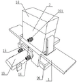
FIG. 1 is a schematic structural view of the present invention;
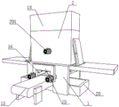
FIG. 2 is a rear first perspective view of the present invention;
FIG. 3 is a second rear perspective view of the present invention;
FIG. 4 is a cross-sectional view of the present invention;
FIG. 5 is an enlarged view of portion A of FIG. 4 in accordance with the present invention;
FIG. 6 is a subjective view of a middle positioning rod and a stop collar of the present invention;
fig. 7 is a subjective view of the middle support rod and the guide block according to the present invention.
The reference numbers in the figures illustrate:
1. a work table; 2. a water tank; 3. a drive rod; 4. a water pressing rod; 5. a through groove; 6. a square groove; 7. positioning a rod; 8. a toothed belt; 9. a first cleaning layer; 10. a second cleaning layer; 11. a fixing strip; 12. a first conveying belt; 13. a second conveying belt; 14. an electric push rod; 15. moving the plate; 16. a support cylinder; 17. a guide block; 18. a filtration device; 181. a filter box; 182. a filter plate; 183. a water pump; 184. a water pumping pipe; 185. a drain pipe; 19. a guide bar; 20. a collection box; 21. a cylinder; 22. a tray; 23. a support bar; 24. a limiting ring; 201. an electric motor.
Detailed Description
The technical solution in the embodiments of the present invention will be clearly and completely described below with reference to the accompanying drawings in the embodiments of the present invention;
example 1:
referring to fig. 1-7, a high-efficiency photovoltaic glass coating cleaning device comprises a workbench 1, a water tank 2 is fixedly connected to the top of the workbench 1 and can be used for storing a mixed liquid of citric acid and water, a driving rod 3 and two water pressing rods 4 are rotatably connected to the inner wall of the water tank 2, a motor 201 is fixedly connected to the back of the water tank 2, an output shaft of the motor 201 penetrates through the water tank 2 and is fixedly connected with the driving rod 3, through grooves 5 are formed in the left side and the right side of the water tank 2, a square groove 6 is formed in the top of the workbench 1, two positioning rods 7 are rotatably connected to the bottom of the workbench 1, a toothed belt 8 is sleeved on the water tank 2, the inner side of the toothed belt 8 is meshed with the driving rod 3, the inner side of the toothed belt 8 is respectively contacted with the two positioning rods 7, the two square grooves 6 and the two through grooves 5, a cleaning layer one 9 which is uniformly distributed is detachably connected to the outer side of the toothed belt 8 through screws, a cleaning layer one 9 which is provided with a cleaning layer two cleaning layer 10, the cleaning layer one cleaning layer 9 which is provided with the cleaning layer two cleaning layers 10, the cleaning layer one 9 and the cleaning layer two layers 10 are respectively provided with a cleaning layer movable plate, two movable plates 16 which are detachably connected to the cleaning layer 14, a cylindrical support plate 16 is connected to the front side of the cleaning layer 1, a cleaning layer 16, two movable plate which is connected to the cleaning layer 16, the guide block 17 is shaped as a cone and the top of the water tank 2 is provided with a filter device 18.
Two driving motors respectively used for driving the supporting cylinders 16 to rotate are installed on one side of the moving plate 15, and arc blocks are fixedly connected to the opposite sides of the two supporting cylinders 16.
When the upper surface and the lower surface of the glass are cleaned simultaneously, the toothed belt 8 is always in a tightened state, a plurality of groups of cleaning layers I9 and cleaning layers II 10 are arranged on the toothed belt 8 and used for absorbing cleaning liquid and achieving the purpose of cleaning photovoltaic glass, the toothed belt 8 can be driven to move through the starting motor 201, the positions of the cleaning layers I9 and cleaning layers II 10 can be changed after the toothed belt 8 moves, the cleaning liquid is stored in the water tank 2, when the cleaning layers I9 and cleaning layers II 10 absorbing the cleaning liquid move to the bottoms of the two positioning rods 7, the bottoms of the cleaning layers I9 and cleaning layers II 10 can be kept in a horizontal arrangement, the electric push rod 14 is started, the electric push rod 14 can drive the movable plate 15 to move towards the front, the movable plate 15 can drive the supporting cylinder 16 and the guide block 17 to move towards the front, the guide block 17 can firstly contact with the cleaning layers I9 and the cleaning layers II 10, the guide block 17 is in a conical arrangement when the cleaning layers I9 and the cleaning layers II 10 contact, the guide block 17 can smoothly pass through the cleaning layers I9 and the cleaning layers 10 after the cleaning layers I9 and the cleaning layers 10 contact with the cleaning layers 10, and the cleaning layers 12, and the cleaning layers 16 can be further, and the cleaning layers 9 and the cleaning layers 12 can be placed on the cleaning layers 9 and the cleaning layers 12 of the cleaning layers 9 and the cleaning layers 10 when the cleaning layers 9 and the cleaning layers 10 of the cleaning layer.
Then the photovoltaic glass can pass through the space between the two supporting cylinders 16, and the thickness of the supporting cylinders 16 is larger than that of the photovoltaic glass, so that the photovoltaic glass can be smoothly inserted into a gap between the first cleaning layer 9 and the second cleaning layer 10, at the moment, a user reversely starts the electric push rod 14, the electric push rod 14 can drive the supporting cylinders 16 to be drawn out from the gap between the first cleaning layer 9 and the second cleaning layer 10, the first cleaning layer 9 and the second cleaning layer 10 can approach each other due to the action of tension until the first cleaning layer 9 and the second cleaning layer 10 are tightly attached to the photovoltaic glass, the first cleaning layer 9 and the second cleaning layer 10 can respectively slide along the top surface and the bottom surface of the photovoltaic glass along with the movement of the photovoltaic glass, and in the sliding process, the cleaning of the photovoltaic glass is realized, the cleaned photovoltaic glass can then contact with the top of the second conveyor belt 13, and the first conveyor belt 12 and the second conveyor belt 13 are started, so that the photovoltaic glass is moved out from the space between the first cleaning layer 9 and the second cleaning layer 10, the cleaning of the photovoltaic glass is realized, and the cleaning efficiency of the photovoltaic glass on double sides of the photovoltaic glass is effectively improved;
and through the washing of cleaning layer one 9 and cleaning layer two 10 to photovoltaic glass, the current mode of washing through the clear water has been replaced, the effectual consumption that reduces the water resource, and then improve the environmental protection ability of device, and after accomplishing a photovoltaic glass washing, when photovoltaic glass passed between cleaning layer one 9 and cleaning layer two 10, the user and start motor 201, motor 201 can drive cleaning layer one 9 and cleaning layer two 10 through cingulum 8 and remove, used cleaning layer one 9 and cleaning layer two 10 can remove to the right side of water tank 2 from the bottom of water tank 2, and unused cleaning layer one 9 and cleaning layer two 10 then can remove to the below of two locating levers 7, the user can wash second photovoltaic glass through repeating above-mentioned operation, accomplish the back to second photovoltaic glass washing.
Similarly, the next cleaning layer I9 and cleaning layer II 10 can be moved to the position below the positioning rod 7 to clean the photovoltaic glass again, the cleaning effect of the cleaning layer I9 and cleaning layer II 10 on the photovoltaic glass can be ensured by continuously replacing the cleaning layer I9 and cleaning layer II 10 in the process, the used cleaning layer I9 and cleaning layer II 10 can enter the water tank 2 from the right side of the water tank 2, the used cleaning layer I9 and cleaning layer II 10 can be soaked in the cleaning liquid after entering the water tank 2, the cleaning liquid can clean the cleaning layer I9 and cleaning layer II 10, the water pressing rod 4 can be contacted with the cleaning layer II 10 when the cleaning layer I9 and cleaning layer II 10 move to the bottom of the water pressing rod 4, and the toothed belt 8 can drive the cleaning layer I9 and cleaning layer II 10 to be extruded on the water pressing rod 4 due to the tight state of the toothed belt 8, the water pressing rod 4 can crush the first cleaning layer 9 and the second cleaning layer 10 to further extrude sewage in the first cleaning layer 9 and the second cleaning layer 10, the sewage can drive dust on the first cleaning layer 9 and the second cleaning layer 10 to further achieve the purpose of cleaning the first cleaning layer 9 and the second cleaning layer 10, when the first cleaning layer 9 and the second cleaning layer 10 move to the top of the driving rod 3, the first cleaning layer 9 and the second cleaning layer 10 lose extrusion, the first cleaning layer 9 and the second cleaning layer 10 can absorb cleaning liquid in the water tank 2, the first cleaning layer 9 and the second cleaning layer 10 move to the top of the left water pressing rod 4, the left water pressing rod 4 can crush the first cleaning layer 9 and the second cleaning layer 10 to further clean the first cleaning layer 9 and the second cleaning layer 10 again, the first cleaning layer 9 and the second cleaning layer 10 can move out from the left through groove 5 after cleaning is completed, and the first cleaning layer 9 and the second cleaning layer 10 can absorb the cleaning liquid in the water tank 2 in the process, and then the photovoltaic glass can be cleaned until the cleaning layer I9 and the cleaning layer II 10 after cleaning are moved to the lower part of the positioning rod 7.
The device can change by very convenient and fast's the first 9 of cleaned layer and the second 10 of cleaned layer, guarantee the cleaning performance of the first 9 of cleaned layer and the second 10 of cleaned layer to photovoltaic glass to at the in-process of changing the first 9 of cleaned layer and the second 10 of cleaned layer, can realize automatic clear purpose to the first 9 of cleaned layer and the second 10 of cleaned layer, effectively save the cost of the first 9 of artifical cleaned layer and the second 10 of cleaned layer, and can promote the cleaning efficiency to photovoltaic glass.
Please refer to fig. 1-4, wherein: the filtering device 18 comprises a filtering box 181, the bottom of the filtering box 181 is fixedly connected with the water tank 2, a filtering plate 182 is mounted on the inner wall of the filtering box 181, a water pump 183 is mounted on the inner wall of the filtering box 181, a water pumping pipe 184 is communicated with the bottom of the water pump 183, the bottom of the water pumping pipe 184 sequentially penetrates through the filtering plate 182 and the filtering box 181 and is communicated with the water tank 2, a water draining pipe 185 is communicated with the bottom of the filtering box 181, and the bottom of the water draining pipe 185 is communicated with the water tank 2.
In the in-process to photovoltaic glass use, the user starts water pump 183, water pump 183 can be with the inside washing liquid of water tank 2 through the top that drinking-water pipe 184 inhales filter 182, filter 182 can filter the washing liquid of taking out after that, the washing liquid after the filtration can fall into inside the rose box 181 and flow back to water tank 2 through drain pipe 185 inside, along with water pump 183's start-up, and then can play filterable effect to the inside washing liquid of water tank 2, and then guarantee the result of use of washing liquid.
Please refer to fig. 4, in which: the two ends of the bottom of the pumping pipe 184 are respectively positioned at the tops of the two water pressing rods 4, and the top of the drainage pipe 185 is positioned at the top of the driving rod 3.
A large amount of sewage can be produced when first cleaning layer 9 and second cleaning layer 10 are extruded, top setting that is located two pressure water poles 4 respectively through drinking-water pipe 184 bottom both ends, the region that can let water pump 183 draw water is located the region that pressure water pole 4 extrudes first cleaning layer 9 and second cleaning layer 10, and then can filter the quick suction of the sewage of extruding, the effectual pollution that reduces sewage to the washing liquid, and can reduce the sewage and appear by the condition that first cleaning layer 9 and second cleaning layer 10 absorbed, first cleaning layer 9 and second cleaning layer 10 are when absorbing the washing liquid, be located the top of actuating lever 3, and the one end of drain pipe 185 backward flow washing liquid is located the top of actuating lever 3, and then can let first cleaning layer 9 and second cleaning layer 10 absorb the washing liquid after filtering, the practicality of effectual improvement device.
Please refer to fig. 4, in which: the inner wall of the square groove 6 and the inner wall of the through groove 5 are both rotatably connected with a guide rod 19, and one side of the guide rod 19 is in contact with the toothed belt 8.
Through the equal guide bar 19 that rotates the connection in square groove 6 inner wall and logical groove 5 inner wall, can reduce frictional force, when improving the device operation smoothness degree, reduce wearing and tearing and improve the life of device.
Please refer to fig. 1-4, wherein: the inner side of the workbench 1 is fixedly connected with a collecting box 20, and the collecting box 20 is positioned below the first cleaning layer 9 and the second cleaning layer 10.
The collection box 20 fixedly connected with the inner side of the workbench 1 can recover the cleaning liquid dropping from the first cleaning layer 9 and the second cleaning layer 10, and the recovered cleaning liquid is utilized, so that the waste of water resources is effectively reduced, and the environment-friendly capacity of the device is improved.
Please refer to fig. 4, in which: the inner wall of the collecting box 20 is fixedly connected with an air cylinder 21, and the top end of the air cylinder 21 is fixedly connected with a tray 22.
The cylinder 21 fixedly connected with the inner wall of the collecting box 20 can drive the tray 22 to ascend, when the photovoltaic glass is cleaned, the tray 22 ascends to support the bottom of the cleaning layer II 10, and further guarantee that the cleaning layer I9 and the cleaning layer II 10 can be tightly attached to the photovoltaic glass, the situation that the photovoltaic glass shakes to cause gaps to appear between the photovoltaic glass and the cleaning layer I9 and the cleaning layer II 10 is reduced, the situation that the photovoltaic glass is not cleaned in place due to the gaps between the photovoltaic glass and the cleaning layer I9 and the cleaning layer II 10 is avoided, and the cleaning effect of the device is improved.
Please refer to fig. 4, in which: the top of tray 22 is fixedly connected with bracing piece 23, and the top of bracing piece 23 is provided with the cambered surface.
The bracing piece 23 through tray 22 top fixed connection can contact with two 10 bottoms on the clean layer of photovoltaic glass both sides at first in-process that tray 22 rises, along with the rising of tray 22, bracing piece 23 can be taut with it after contacting with two 10 on clean layer, and then can let two 10 on clean layer can be better hug closely with photovoltaic glass, improve photovoltaic glass's clean effect.
Please refer to fig. 4 and 7, wherein: the locating rod 7 is sleeved with two limiting rings 24 fixedly connected with the locating rod, and one opposite sides of the two limiting rings 24 are in contact with the toothed belt 8.
The limiting ring 24 sleeved on the positioning rod 7 can limit the toothed belt 8, the friction force between the photovoltaic glass and the first cleaning layer 9 and between the photovoltaic glass and the second cleaning layer 10 drives the toothed belt 8 to deviate, the positions of the toothed belt 8, the first cleaning layer 9 and the second cleaning layer 10 are kept stable, and the practicability of the device is improved.
Example 2:
based on the specific implementation details of the embodiment, when only one side of the glass needs to be cleaned, the scheme only needs to start the driving motor to drive the guide block 17 to rotate, the specific rotation mode is (see the view angle of fig. 7), the left guide block 17 rotates anticlockwise, the right guide block 17 rotates clockwise, and the circular arc block arranged on the guide block 17 can rotate downwards for a certain angle at the same time, at the moment, because the supporting cylinder 16 is of a cylindrical structure, the left guide block 17 and the right guide block 17 do not excessively extrude the first cleaning layer 9 while rotating, but the circular arc block can push the second cleaning layer 10 downwards for a distance; at this time, the air cylinder 21 is also required to drive the tray 22 to descend for a certain distance so as to adapt to the movement trend;
at the moment, when the glass passes through the first cleaning layer 9 and the second cleaning layer 10, only the first cleaning layer 9 cleans the top of the glass, and the second cleaning layer 10 does not participate; in the mode, the change of cleaning the single side of the glass can be completed without manually taking part in the disassembly between the first cleaning layer 9 and the second cleaning layer 10;
similarly, the detachable arrangement between the first cleaning layer 9 and the second cleaning layer 10 can be used as an alternative of this embodiment, that is, the purpose of single-side cleaning can be achieved by manually separating the second cleaning layer 10 from the first cleaning layer 9 directly through the hook and loop fastener.
The above are merely preferred embodiments of the present invention; the scope of the invention is not limited thereto. Any person skilled in the art should be able to cover the technical scope of the present invention by equivalent or modified solutions and modifications within the technical scope of the present invention.
Claims (8)
1. The utility model provides a high-efficient photovoltaic glass coating film belt cleaning device, includes workstation (1), its characterized in that: the top of the workbench (1) is fixedly connected with a water tank (2), and the inner wall of the water tank (2) is rotatably connected with a driving rod (3) and two water pressing rods (4);
the back surface of the water tank (2) is fixedly connected with a motor (201), an output shaft of the motor (201) penetrates through the water tank (2) and is fixedly connected with a driving rod (3), through grooves (5) are formed in the left side and the right side of the water tank (2), a square groove (6) is formed in the top of the workbench (1), two positioning rods (7) are rotatably connected to the bottom of the workbench (1), a toothed belt (8) is sleeved on the water tank (2), the inner side of the toothed belt (8) is meshed with the driving rod (3), the inner side of the toothed belt (8) is respectively contacted with the two positioning rods (7), the two square grooves (6) and the two through grooves (5), the outer side of the toothed belt (8) is detachably connected with cleaning layers I (9) which are uniformly distributed through screws, cleaning layers II (10) are arranged on the outer sides of the cleaning layers I (9), and the cleaning layers I (9) and II (10) are elastic; two fixing strips (11) are detachably connected between the first cleaning layer (9) and the second cleaning layer (10), and the bottoms of the two water pressing rods (4) are both contacted with the second cleaning layer (10);
the cleaning device comprises a workbench (1), wherein a first conveying belt (12) and a second conveying belt (13) are respectively installed on the front side and the back side of the workbench (1), an electric push rod (14) fixedly connected with the workbench (1) penetrates through the back side of the workbench (1), a moving plate (15) is fixedly connected to one end of the back side of the electric push rod (14), two supporting cylinders (16) are arranged on the front side of the moving plate (15), the tops and the bottoms of the two supporting cylinders (16) are respectively contacted with a first cleaning layer (9) and a second cleaning layer (10), a guide block (17) is fixedly connected to one end of the front side of each of the two supporting cylinders (16), the guide blocks (17) are arranged in a conical shape, and a filtering device (18) is arranged at the top of a water tank (2);
two driving motors used for driving the supporting cylinders (16) to rotate are installed on one side of the moving plate (15), and arc blocks are fixedly connected to one sides of the supporting cylinders (16) which are opposite to each other.
2. The efficient cleaning device for the photovoltaic glass coating according to claim 1, wherein: the filter device (18) comprises a filter box (181), the bottom of the filter box (181) is fixedly connected with a water tank (2), a filter plate (182) is installed on the inner wall of the filter box (181), a water pump (183) is installed on the inner wall of the filter box (181), the bottom of the water pump (183) is communicated with a water pumping pipe (184), the bottom of the water pumping pipe (184) sequentially penetrates through the filter plate (182) and the filter box (181) and is communicated with the water tank (2), the bottom of the filter box (181) is communicated with a water drainage pipe (185), and the bottom of the water drainage pipe (185) is communicated with the water tank (2).
3. The efficient cleaning device for the photovoltaic glass coating according to claim 2, wherein: the two ends of the bottom of the water pumping pipe (184) are respectively located at the tops of the two water pressing rods (4), and the top of the water discharging pipe (185) is located at the top of the driving rod (3).
4. The efficient cleaning device for the coated photovoltaic glass of claim 1, which is characterized in that: the inner wall of square groove (6) and the inner wall of logical groove (5) all rotate and are connected with guide bar (19), one side and cingulum (8) of guide bar (19) contact.
5. The efficient cleaning device for the coated photovoltaic glass of claim 1, which is characterized in that: the inner side of the workbench (1) is fixedly connected with a collection box (20), and the collection box (20) is located below the first cleaning layer (9) and the second cleaning layer (10).
6. The efficient cleaning device for the photovoltaic glass coating film according to claim 5, wherein: the inner wall of the collection box (20) is fixedly connected with an air cylinder (21), and the top end of the air cylinder (21) is fixedly connected with a tray (22).
7. The efficient cleaning device for the photovoltaic glass coating film according to claim 6, wherein: the top of tray (22) is fixedly connected with bracing piece (23), the top of bracing piece (23) is provided with the cambered surface.
8. The efficient cleaning device for the photovoltaic glass coating according to claim 1, wherein: the locating lever (7) is sleeved with two limiting rings (24) fixedly connected with the locating lever, and the two limiting rings (24) are in contact with the toothed belt (8) on the opposite sides.
Priority Applications (1)
| Application Number | Priority Date | Filing Date | Title |
|---|---|---|---|
| CN202211705163.0A CN115672915B (en) | 2022-12-29 | 2022-12-29 | High-efficient photovoltaic glass coating film belt cleaning device |
Applications Claiming Priority (1)
| Application Number | Priority Date | Filing Date | Title |
|---|---|---|---|
| CN202211705163.0A CN115672915B (en) | 2022-12-29 | 2022-12-29 | High-efficient photovoltaic glass coating film belt cleaning device |
Publications (2)
| Publication Number | Publication Date |
|---|---|
| CN115672915A true CN115672915A (en) | 2023-02-03 |
| CN115672915B CN115672915B (en) | 2023-03-10 |
Family
ID=85055793
Family Applications (1)
| Application Number | Title | Priority Date | Filing Date |
|---|---|---|---|
| CN202211705163.0A Active CN115672915B (en) | 2022-12-29 | 2022-12-29 | High-efficient photovoltaic glass coating film belt cleaning device |
Country Status (1)
| Country | Link |
|---|---|
| CN (1) | CN115672915B (en) |
Citations (7)
| Publication number | Priority date | Publication date | Assignee | Title |
|---|---|---|---|---|
| CN213194675U (en) * | 2020-07-30 | 2021-05-14 | 河南天扬光电科技有限公司 | Cleaning device for liquid crystal display panel |
| CN113328688A (en) * | 2021-05-12 | 2021-08-31 | 南京泰乐新能源技术研究院有限公司 | Novel self-cooling photovoltaic glass |
| CN114273364A (en) * | 2021-12-15 | 2022-04-05 | 万津实业(赤壁)有限公司 | Glass repair equipment |
| CN114643256A (en) * | 2022-03-04 | 2022-06-21 | 苏州朗坤自动化设备股份有限公司 | Glass cover plate surface cleaning equipment |
| CN114669568A (en) * | 2017-07-12 | 2022-06-28 | 哈里斯股份有限公司 | Cleaning system |
| CN217070069U (en) * | 2021-12-03 | 2022-07-29 | 南京索尔玻璃科技股份有限公司 | Knurling solar energy coating film photovoltaic glass belt cleaning device |
| CN115321830A (en) * | 2021-10-20 | 2022-11-11 | 江苏城乡建设职业学院 | Conductive glass coating method and device with self-repairing function |
-
2022
- 2022-12-29 CN CN202211705163.0A patent/CN115672915B/en active Active
Patent Citations (7)
| Publication number | Priority date | Publication date | Assignee | Title |
|---|---|---|---|---|
| CN114669568A (en) * | 2017-07-12 | 2022-06-28 | 哈里斯股份有限公司 | Cleaning system |
| CN213194675U (en) * | 2020-07-30 | 2021-05-14 | 河南天扬光电科技有限公司 | Cleaning device for liquid crystal display panel |
| CN113328688A (en) * | 2021-05-12 | 2021-08-31 | 南京泰乐新能源技术研究院有限公司 | Novel self-cooling photovoltaic glass |
| CN115321830A (en) * | 2021-10-20 | 2022-11-11 | 江苏城乡建设职业学院 | Conductive glass coating method and device with self-repairing function |
| CN217070069U (en) * | 2021-12-03 | 2022-07-29 | 南京索尔玻璃科技股份有限公司 | Knurling solar energy coating film photovoltaic glass belt cleaning device |
| CN114273364A (en) * | 2021-12-15 | 2022-04-05 | 万津实业(赤壁)有限公司 | Glass repair equipment |
| CN114643256A (en) * | 2022-03-04 | 2022-06-21 | 苏州朗坤自动化设备股份有限公司 | Glass cover plate surface cleaning equipment |
Also Published As
| Publication number | Publication date |
|---|---|
| CN115672915B (en) | 2023-03-10 |
Similar Documents
| Publication | Publication Date | Title |
|---|---|---|
| CN109023772B (en) | Gauze production is with washing drying device | |
| CN111974724A (en) | Photovoltaic panel cleaning machine with double-degree-of-freedom structure | |
| CN212850408U (en) | Automatic clear solar photovoltaic plate structure | |
| CN115672915B (en) | High-efficient photovoltaic glass coating film belt cleaning device | |
| CN217665267U (en) | First-order belt cleaning device of on-vehicle AG glass production line | |
| CN217342740U (en) | Photovoltaic solar panel cleaning and maintaining device | |
| CN112047435B (en) | Curtain type sewage treatment equipment and using method thereof | |
| CN115043449A (en) | Textile dyeing process water treatment equipment capable of reducing environmental pollution | |
| CN108372174B (en) | Circulating device of glass cleaning machine | |
| CN220401697U (en) | Solar panel with cleaning function | |
| CN215902395U (en) | Full-automatic fermentation box cleaning machine | |
| CN219953607U (en) | Air inlet device of air compressor | |
| CN217986527U (en) | Raw materials belt cleaning device is used in animal casing processing | |
| CN217698247U (en) | Printing production waste liquid treatment device | |
| CN113145607B (en) | A recovery unit for copper scrap utilizes | |
| CN220892641U (en) | Efficient cooling treatment device for polished pumping rod | |
| CN220334806U (en) | Rural domestic sewage treatment system | |
| CN215481490U (en) | Doubling winder is used in canvas production | |
| CN212468933U (en) | Novel photovoltaic board is clean device | |
| CN215968604U (en) | Supplementary waterproof detection device of accessory for cell-phone processing production | |
| CN220257297U (en) | Vacuum belt filter | |
| CN220992034U (en) | Raw material cleaning equipment | |
| CN215112399U (en) | Solar street lamp with photovoltaic panel dust removal device | |
| CN217092656U (en) | Dust collecting device for plastic burning plate dust removing equipment | |
| CN218532080U (en) | Novel cleaning device for plate heat exchanger |
Legal Events
| Date | Code | Title | Description |
|---|---|---|---|
| PB01 | Publication | ||
| PB01 | Publication | ||
| SE01 | Entry into force of request for substantive examination | ||
| SE01 | Entry into force of request for substantive examination | ||
| GR01 | Patent grant | ||
| GR01 | Patent grant |