CN115649972A - Yarn coiling mechanism is used in cotton yarn production and processing - Google Patents
Yarn coiling mechanism is used in cotton yarn production and processing Download PDFInfo
- Publication number
- CN115649972A CN115649972A CN202211653159.4A CN202211653159A CN115649972A CN 115649972 A CN115649972 A CN 115649972A CN 202211653159 A CN202211653159 A CN 202211653159A CN 115649972 A CN115649972 A CN 115649972A
- Authority
- CN
- China
- Prior art keywords
- staggered power
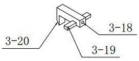
- staggered
- pile
- power pile
- piles
- Prior art date
- Legal status (The legal status is an assumption and is not a legal conclusion. Google has not performed a legal analysis and makes no representation as to the accuracy of the status listed.)
- Granted
Links
Images




Classifications
-
- Y—GENERAL TAGGING OF NEW TECHNOLOGICAL DEVELOPMENTS; GENERAL TAGGING OF CROSS-SECTIONAL TECHNOLOGIES SPANNING OVER SEVERAL SECTIONS OF THE IPC; TECHNICAL SUBJECTS COVERED BY FORMER USPC CROSS-REFERENCE ART COLLECTIONS [XRACs] AND DIGESTS
- Y02—TECHNOLOGIES OR APPLICATIONS FOR MITIGATION OR ADAPTATION AGAINST CLIMATE CHANGE
- Y02W—CLIMATE CHANGE MITIGATION TECHNOLOGIES RELATED TO WASTEWATER TREATMENT OR WASTE MANAGEMENT
- Y02W30/00—Technologies for solid waste management
- Y02W30/50—Reuse, recycling or recovery technologies
- Y02W30/66—Disintegrating fibre-containing textile articles to obtain fibres for re-use
Landscapes
- Preliminary Treatment Of Fibers (AREA)
Abstract
The invention discloses a yarn winding device for cotton yarn production and processing, which comprises a movable support base, a staggered quincuncial pile type integrated power mechanism, an elastically adjustable winding frame, a seesaw type control guide plate, a buckle type steel ball extrusion control roller, a detachable scraping type cotton yarn impurity removal box and a guide wire combination.
Description
Technical Field
The invention belongs to the technical field of cotton yarn winding devices, and particularly relates to a yarn winding device for cotton yarn production and processing.
Background
The cotton yarn is a yarn formed by processing cotton fibers through a spinning process, and is called a cotton thread after stranding processing. According to different spinning processes, the spun yarns can be divided into the carded yarns and the combed yarns, and the carded yarns or the combed yarns are rolled into a tube after being processed by a common processing procedure, so that the subsequent use is facilitated, the quality of the cotton yarns directly influences the appearance, the wear resistance and the durability of subsequent fabrics, the quality of the yarns is closely related to the production management, the process conditions, the mechanical conditions, the technical operation level, the quality of raw cotton and the reasonable use condition of the raw cotton, and the quality and the efficiency of yarn rolling are crucial as the first step of preparation before weaving.
For the application needs, various yarn coiling mechanisms in the market are produced at the same time, but the existing cotton yarn coiling mechanism still has the following defects in actual use:
1. the winding and arranging mode of the winding device is single or the winding is not uniform, so that the problems of disordered cotton yarn arrangement and inconvenient use after winding are caused;
2. the winding device uses a large amount of electric energy, the production energy consumption is too high, and the processing cost is increased;
3. in the winding process, the cotton yarn can not continuously maintain tension, so that the problem that the cotton yarn can not be wound, loosened and formed into a tube is caused;
4. the winding device is single and fixed in size, cannot adapt to winding drums of various types, and is low in production efficiency;
5. in the winding process, impurity removal of cotton yarns is not carried out, or the original physical and mechanical properties of the yarns are damaged, so that the quality of the cotton yarns is low, and subsequent processing cannot be carried out.
Therefore, to solve the above problems, an improved apparatus is urgently required.
Disclosure of Invention
In order to solve the existing problems, the invention provides a yarn winding device for cotton yarn production and processing, which only uses single power to achieve the purpose of different rotation tracks through a turntable structure in order to solve the problem of disordered cotton yarn arrangement, realizes the technical effect of uniformly winding the cotton yarn in a staggered track manner while rotating and winding, saves cost and energy consumption, and has high bobbin forming efficiency; by utilizing the elastic property of the spring combination, the elastic adjustable winding frame can effectively control the stretching length and the winding diameter of the elastic adjustable winding frame, can be suitable for winding drums with various sizes and models, greatly improves the winding efficiency, and is convenient to disassemble; the buckle type steel ball extrusion control roller is arranged, so that the cotton yarn is always in a relaxation state in the winding process, the contradiction technical problem that the cotton yarn needs to be fed (the original mechanical property of the cotton yarn is damaged by simple extrusion control) but cannot be fed (the cotton yarn in the winding process is loosened by automatic feeding) is solved, the good winding forming of the cotton yarn is ensured, and the technical effect of effectively removing impurities such as fluff, dust and weak yarn on the cotton yarn without external power is realized through the detachable scraping type cotton yarn impurity removing box.
In order to achieve the purpose, the technical scheme adopted by the invention is as follows: the invention relates to a yarn winding device for cotton yarn production and processing, which comprises a movable supporting base, a staggered quincuncial pile type integrated power mechanism, an elastically adjustable winding frame, a rocker type control guide plate, a buckle type steel ball extrusion control roller, a detachable scraping type cotton yarn impurity removal box and a directional guide combination, wherein the staggered quincuncial pile type integrated power mechanism is arranged above the movable supporting base, the elastically adjustable winding frame is arranged above the staggered quincuncial pile type integrated power mechanism, four elastically adjustable winding frames are uniformly distributed along the circumferential direction of the staggered quincuncial pile type integrated power mechanism, the rocker type control guide plate is arranged above the staggered quincuncial pile type integrated power mechanism, the buckle type steel ball extrusion control roller is arranged above the rocker type control guide plate, the detachable scraping type cotton yarn impurity removal box is arranged above the buckle type steel ball extrusion control roller, and the directional guide combination is arranged above the detachable scraping type cotton yarn impurity removal box; the staggered quincuncial pile type integrated power mechanism comprises a motor fixing frame, a motor, a rotary table, a quincuncial gear, a driving power pile, a staggered power pile I, a staggered power pile II, a staggered power pile III, a staggered power pile IV, a staggered power pile V, a staggered power pile six, a staggered power pile seven, a staggered power pile eight, a staggered power pile nine, a staggered power pile ten, a staggered power pile eleven and a staggered power pile twelve, wherein the motor fixing frame is arranged on a movable supporting base, the motor is arranged in the motor fixing frame, the rotary table is arranged above the motor, the rotary table is connected with the output end of the motor, the quincuncial gear is arranged on the movable supporting base, the quincuncial gear is uniformly distributed with four in the circumferential direction of the rotary table, the driving power piles are uniformly distributed at the lower part of the rotary table in the circumferential direction, and the driving power pile is meshed with the quincuncial gear, the staggered power pile I, the staggered power pile II, the staggered power pile III, the staggered power pile IV, the staggered power pile V, the staggered power pile VI, the staggered power pile VII, the staggered power pile eight, the staggered power pile nine, the staggered power pile ten, the staggered power pile eleven and the staggered power pile twelve are uniformly distributed on the upper part of the turntable along the circumferential direction, the staggered power piles are symmetrically arranged on two sides of the staggered power pile I, the staggered power pile trisymmetrically arranged on the side surface of the staggered power pile II, the staggered power pile tetrasymmetrically arranged on the side surface of the staggered power pile III, the staggered power pile penta arranged on the side surface of the staggered power pile IV, the staggered power pile hexa symmetrically arranged on the side surface of the staggered power pile five, the staggered power pile heptasymmetrically arranged on the side surface of the staggered power pile six, the staggered power pile octasymmetry arranged on the side surface of the staggered power pile VII, the staggered power pile nona symmetrically arranged on the side surface of the staggered power pile eight, the staggered power piles are arranged on the lateral surfaces of the staggered power piles, and the staggered power piles are symmetrically arranged on the opposite surfaces of the staggered power piles along the axis of the rotary table.
Further, the second staggered power pile is higher than the first staggered power pile, the third staggered power pile is higher than the second staggered power pile, the fourth staggered power pile is higher than the third staggered power pile, the fifth staggered power pile is higher than the fourth staggered power pile, the sixth staggered power pile is higher than the fifth staggered power pile, the seventh staggered power pile is higher than the sixth staggered power pile, the eighth staggered power pile is higher than the seventh staggered power pile, the ninth staggered power pile is higher than the eighth staggered power pile, the tenth staggered power pile is higher than the ninth staggered power pile, the eleventh staggered power pile is higher than the tenth staggered power pile, the twelfth staggered power pile is higher than the eleventh staggered power pile, the height intervals are equal, continuous and uniform high-low-level drop tracks are formed, only single power is utilized, the purpose of different rotating tracks is achieved through a turntable structure, the technical effect of uniform high-low-level drop track arrangement is achieved while cotton yarns are rotated and wound, the cost and the energy consumption are saved, and the transportation efficiency and the subsequent transportation efficiency are convenient.
Preferably, the tops of the staggered power pile I, the staggered power pile II, the staggered power pile III, the staggered power pile IV, the staggered power pile V, the staggered power pile VI, the staggered power pile VII, the staggered power pile VIII, the staggered power pile VII and the staggered power pile VII are arranged in a spherical shape, so that the continuity of staggered tracks is improved, and the transition is smoother.
Further, the winding frame with adjustable elasticity comprises a winding frame seat, a first clamping plate, a second clamping plate, a cambered spring plate, a cambered supporting plate, a first stretching spring, a second stretching spring, a compression spring and a stretching plate, wherein the winding frame seat is arranged above the plum gear, clamping grooves are uniformly distributed on the lower portion of the winding frame seat along the circumferential direction, a compression support column is arranged in the middle of the winding frame seat, limiting grooves are uniformly distributed and penetrated along the circumference of the compression support column by the winding frame seat, the limiting grooves correspond to the clamping grooves, one clamping plate is respectively and slidably arranged in the clamping grooves, the cambered spring plate is respectively and vertically arranged at one end of the first clamping plate through the limiting grooves, the cambered spring plate slides in the limiting grooves, a spring plate groove is not penetrated on the extrados surface of the cambered spring plate, two clamping plates are respectively arranged at the lower portion of the cambered spring plate, and two clamping plates are respectively arranged at the lower portion of the spring plate groove, the second clamping plate corresponds to the first clamping plate in position, sliding grooves are symmetrically formed in two sides of the inner edge of the elastic plate groove, the cambered supporting plates are respectively arranged on the upper portions of the cambered elastic plates, supporting plate inserts are arranged at the lower ends of the cambered supporting plates, the supporting plate inserts are embedded in the elastic plate groove, sliding blocks are symmetrically arranged on two sides of the supporting plate inserts and slide in the sliding grooves, the cambered supporting plates are matched with the cambered elastic plates, the cambered supporting plates are arranged in an inverted L shape, one stretching spring is respectively and uniformly distributed in the elastic plate groove, the lower end of the supporting plate insert is respectively connected with the cambered elastic plates through one stretching spring, the two stretching springs are respectively and uniformly distributed in the inner sides of the supporting plate inserts, the two stretching springs are respectively connected with the upper ends of the cambered elastic plates and the cambered supporting plates, and the first stretching springs and the second stretching springs are at least provided with 3 groups, the inboard of cambered surface springboard is located along vertical direction equipartition respectively to compression spring, compression spring connects cambered surface springboard and compression pillar, compression spring sets up 5 groups at least, the top of cambered surface fagging is located respectively to the extension plate, the extension plate is the shape of falling L and sets up, utilizes the elasticity characteristic of spring combination, and the flexible length and the rolling diameter of the adjustable rolling frame of control elasticity are applicable in the rolling section of thick bamboo of various size models, have improved rolling efficiency greatly, and the rolling section of thick bamboo dismantles convenient and fast.
Further, the top outside of cambered surface fagging is embedded respectively and is equipped with the location inserted block, the one end of location inserted block is equipped with the location trip, the middle part of location inserted block does not run through and is equipped with the locating hole, the top correspondence of cambered surface fagging is equipped with the inserted block spout, the inside of inserted block spout is equipped with the location slide bar, the location inserted block passes through the locating hole and slides on the slide bar of location, the bilateral symmetry of inserted block spout is equipped with the location spout, the location spout is the rectangle setting, the location spout is close to the cambered surface fagging inboard side and is equipped with the inserted block spring respectively, the bilateral symmetry of location inserted block is equipped with the inserted block gag lever post, the inserted block gag lever post links to each other with the inserted block spring, the inserted block gag lever post slides in the location spout, and the setting up of location inserted block makes the receipts reel of different models can stably fix on the adjustable rolling up of elasticity.
Further, the length of screens board one and screens board two is greater than the length in screens groove, when guaranteeing the installation winding drum, the stability of the adjustable rolling frame of elasticity, the inner wall cambered surface radius of cambered surface diving board equals the radius of compression pillar, and the cambered surface diving board inner wall is collapsible to compression pillar surface, increases the winding drum size range of suitability.
Further, portable support base includes backup pad, universal wheel, center pillar and base pillar, the lower part of motor mount is located to the backup pad, the backup pad is the rectangle setting, the four corners of backup pad lower part is located respectively to the universal wheel, the four corners on backup pad upper portion is located respectively to the base pillar, the center pillar is located on the motor mount, the plum blossom gear rotates respectively and locates on the base pillar for this yarn coiling mechanism can remove in a flexible way, can carry out the rolling of four cotton yarn groups simultaneously, and it is convenient to use, has increased rolling efficiency.
Further, seesaw control wire guide is including solid fixed ring, fixed axle, location wire post, location wire wheel, seesaw, guide pulley support, wire support and lead wire ring, gu fixed ring locates on the center pillar, the top of the power pile that falls by mistake is located to the fixed ring, location wire post is located on the center pillar along the circumferencial direction equipartition, gu fixed ring's top is located to the location wire post, the position of location wire post is corresponding with the position of base pillar, location wire wheel rotates and locates on the location wire post, the fixed axle is located gu fixed ring along the circumferencial direction equipartition, the position of fixed axle is corresponding with the position of base pillar, the one end of seesaw is rotated and is located on the fixed axle, guide pulley support symmetry is located on the seesaw, the guide pulley rotates and locates the upper portion of guide pulley support, the vertical one of locating the seesaw and keeping away from the center pillar of wire support is served, the upper portion of wire support is located to the lead wire ring.
As preferably, the bottom of wane is circular-arc setting, the length of wane is greater than the distance of the power pile that misplaces to the center pillar, the anchor ring of lead ring is the sphere setting, the smooth no edges and corners in surface of lead ring, nimble pivoted wane cooperation dislocation plum blossom stake formula integration power unit for the lead ring drives cotton yarn and reciprocates, has realized the winding displacement of two directions through single power, makes a rolling section of thick bamboo when the rotatory line of receipts, realizes the technological effect of even winding displacement from top to bottom.
Further, buckle formula steel ball extrusion control roller is located on the central pillar along the circumferencial direction equipartition, the position of buckle formula steel ball extrusion control roller corresponds with the position of wane formula control wire board, buckle formula steel ball extrusion control roller includes dead lever, axis of rotation, dwang, fixed squeeze roll, rotation squeeze roll and ellipsoid steel ball, the axis of rotation is located on the central pillar along the circumferencial direction equipartition, the dwang rotates respectively and locates on the axis of rotation, the dead lever is located on the central pillar along the circumferencial direction equipartition, fixed squeeze roll locates on the dead lever, be equipped with steel ball recess two on the circumference of fixed squeeze roll, rotation squeeze roll locates on the dwang, be equipped with steel ball recess one on the circumference of rotation squeeze roll, the ellipsoid steel ball closely arranges and locates in steel ball recess one and steel ball recess two, fixed squeeze roll and rotation squeeze roll set up relatively, the bilateral symmetry of steel ball recess two is equipped with the buckle groove, the inside in the buckle groove is equipped with the control spring respectively, run through on the both sides wall of fixed squeeze roll be equipped with control button, the inboard of control button is equipped with interior buckle tooth respectively, interior latch tooth is equipped with the outer latch tooth, the outer both sides of control spring, the outer latch tooth is equipped with the position corresponding with the buckle groove, the buckle tooth, the position of steel ball.
Preferably, the surfaces of the ellipsoidal steel balls are smooth and have no edges and corners, the middle sections of the ellipsoidal steel balls are curved surfaces rather than spherical surfaces, the fixed extrusion roller and the rotating extrusion roller are fastened with the outer snap teeth through the inner snap teeth to enable the middle sections of the ellipsoidal steel balls to be attached, cotton yarns are extruded, the ellipsoidal steel balls cannot be fed automatically due to no external power of the ellipsoidal steel balls, and only friction force generated by movement of the cotton yarns enables the ellipsoidal steel balls to rotate and feed the yarns.
Further, can dismantle strike-off formula cotton thread edulcoration case and locate on the center pillar along the circumferencial direction equipartition, can dismantle the position of strike-off formula cotton thread edulcoration case and the position of buckle formula steel ball extrusion control roller corresponding, can dismantle strike-off formula cotton thread edulcoration case and include jack box groove, box, case lid, fixed plate, first edulcoration scraper blade, second edulcoration scraper blade, light axle and brush hair doctor-bar, the jack box groove is located on the center pillar along the circumferencial direction, the fixed plate slides and locates the jack box inslot, the upper end of fixed plate is located to the box, the case lid block is located box upper portion, the case lid is equipped with the through wires hole, the position that the box corresponds the through wires hole is equipped with the wire hole, the below of through wires hole is located to first edulcoration scraper blade, second edulcoration scraper blade is located on the wire hole, the upper portion of first edulcoration scraper blade is equipped with threading opening one, the upper portion of second edulcoration scraper blade is equipped with threading opening two, the both sides of threading opening two are located to light axle symmetry, brush hair doctor-bar equipartition is located on the circumference of light axle, through the cooperation of jack box groove with the fixed plate, has realized the quick clearance of dismantling the cotton thread edulcoration case, and convenient dismantlement removal and convenient dismantlement is dismantled, and convenient to use.
Further, first edulcoration scraper blade and second edulcoration scraper blade are coniform setting, the diameter of threading opening one is greater than threading opening two, and cotton yarn is preferred to pass through the great threading opening one of diameter, strikes off fine hair and the floating dust on the cotton yarn, and the rethread diameter is less threading opening two, effectively gets rid of the dirt bits etc. that attach to on cotton yarn. Preferably, the end of the bristle scraping blade is symmetrically provided with bristle barbs, the end of the bristle scraping blade is tangent to the second impurity removal scraper, the bristle scraping blade and the bristle barbs are made of ultrathin light materials, and under the condition of no external power, the bristle barbs are driven to move only through directional movement of cotton yarns, so that the light shaft is driven to rotate, the bristle barbs continuously scrape the cotton yarns, weak yarns on the cotton yarns are removed, and meanwhile, dust, impurities and the like at the second threading opening are scraped.
Furthermore, the fixed guide wire combination is uniformly distributed on the central pillar along the circumferential direction, the position of the fixed guide wire combination corresponds to the position of the detachable scraping type cotton thread impurity removal box, the fixed guide wire combination comprises a support column, a fixed guide wire wheel, a guide wire bent rod and a guide wire ring, the support column is arranged on the central pillar, the fixed guide wire wheel is rotatably arranged on the support column, the guide wire bent rod is arranged on the upper part of the central pillar, the guide wire bent rod is arranged above the support column, the guide wire ring is arranged at one end, far away from the central pillar, of the guide wire bent rod, a wire pressing groove is formed in the circumference of the fixed guide wire wheel, the inner part of the wire pressing groove is in an arc surface arrangement, the ring surface of the guide wire ring is in a spherical surface arrangement, and the surface of the guide wire ring is smooth and has no edge angle.
Preferably, the axis of the yarn pressing groove, the first threading opening and the second threading opening are arranged on the same axis with the vertical central line of the binding surfaces of the fixed squeezing roller and the rotating squeezing roller, so that the cotton yarn is ensured to keep the same-direction tension in the winding process, the damage of the cotton yarn is reduced, and the original physical and mechanical properties of the yarn are kept.
The invention with the structure has the following beneficial effects:
1. the yarn winding device for cotton yarn production and processing achieves the purpose of different rotating tracks through the turntable structure by using only single power, achieves the technical effect of uniformly winding the cotton yarn in a staggered track at high and low positions while rotating and winding, saves cost and energy consumption, has high bobbin forming efficiency, and is convenient for subsequent transportation and storage.
2. The adjustable rolling frame of elasticity has been set up, utilizes the elasticity characteristic of spring combination, and the flexible length and the rolling diameter of the adjustable rolling frame of control elasticity are applicable in the winding drum of various size models, and wherein, the stability of the adjustable rolling frame of elasticity has been guaranteed in the setting of screens board one and screens board two, and the setting of location inserted block makes the winding drum of various models stabilize on the adjustable rolling frame of elasticity, has improved rolling efficiency greatly, and the winding drum dismantles convenient and fast.
3. The middle section of the ellipsoid steel ball is attached to extrude cotton yarns by the aid of the buckling type steel ball extrusion control roller, the ellipsoid steel ball has no external power and cannot automatically feed the yarns, and only friction force generated by movement of the cotton yarns enables the ellipsoid steel ball to rotate to feed the yarns.
4. The fixed squeeze roll and the rotating squeeze roll are arranged, and the technical effect of quickly feeding and taking lines is achieved through the fastening of the inner clamping teeth and the outer clamping teeth, and the device is simple in structure and convenient to operate.
5. Through adopting the sleek wang type control wire board of bottom surface, nimble cooperation is misplaced plum blossom stake formula integration power unit, has ensured cotton yarn at the smoothness nature of vertical direction winding displacement, and cotton yarn walks the line changeover portion and be slick and sly rotating-structure, and is rational in infrastructure, can not harm cotton yarn original mechanical properties.
6. According to the condition that has the fault on the raw cotton yarn, set up and to have dismantled scraping formula cotton thread edulcoration case, through the scraping effect of first edulcoration scraper blade and second edulcoration scraper blade, reach the purpose of cleaing away impurity such as fine hair, dirt bits on the cotton yarn, simultaneously, the brush hair doctor-bar that has brush hair barb drives the rotation through directional motion's cotton yarn, on the one hand hooks the weak yarn on the cotton yarn, and on the other hand clears away the impurity that threading opening two departments scraped.
7. Through the plug cooperation setting of box inserting groove and fixed plate, realized dismantling the quick dismantlement of scraping formula cotton thread edulcoration case, and the block setting of case lid and box, convenient clearance, it is convenient to use.
8. The central axes of the cotton yarn routing paths are all on the same axis, and the structures through which the cotton yarns pass are all set to be smooth round surfaces, so that the cotton yarns are ensured to keep tension in the same direction in the winding process, the damage of the cotton yarns is reduced, and the original physical and mechanical properties of the yarns are kept.
9. The four-group cotton yarn winding device is compact in structure, four groups of cotton yarn winding structures are respectively arranged in the circumferential direction of the central support column, four groups of cotton yarns can be simultaneously wound through the positioning of the wire guide rings and the wire pressing grooves, the production efficiency is greatly improved, finished products are saved, and in addition, the movable supporting base is provided with the universal wheels, so that the use is convenient and fast, and the operation is stable.
In a word, the yarn winding device for cotton yarn production and processing is compact in overall structure, efficient, energy-saving, stable in operation and convenient and fast to use.
Drawings
FIG. 1 is a schematic structural view of a yarn winding device for cotton yarn production and processing provided by the invention;
FIG. 2 is a front view of a yarn winding device for cotton yarn production and processing provided by the invention;
fig. 3 is a schematic structural view of a staggered quincuncial pile type integrated power mechanism and a movable support base;
fig. 4 is a schematic view of the bottom structure of the staggered quincuncial pile type integrated power mechanism;
FIG. 5 is a schematic structural view of an elastically adjustable winding frame;
FIG. 6 is a schematic structural view of a first clamping plate, a second clamping plate, a cambered spring plate and a cambered supporting plate;
FIG. 7 is a schematic view of a rolling stand;
FIG. 8 is a schematic view of the internal structure of the insert sliding groove and the positioning sliding groove;
FIG. 9 is a schematic view of a positioning block;
FIG. 10 is a schematic structural view of a snap-in type steel ball extrusion control roller;
FIG. 11 is a schematic view showing the structure of the opposite surfaces of a fixed squeeze roll and a rotating squeeze roll;
FIG. 12 is a schematic view of an ellipsoidal steel ball structure;
FIG. 13 is a schematic view of a detachable scraping type cotton thread impurity removing box;
fig. 14 is a schematic view of a partial structure at a in fig. 13 according to the present invention.
Wherein, 1, a movable supporting base, 2, a staggered quincuncial pile type integrated power mechanism, 3, an elastic adjustable winding frame, 4, a seesaw type control wire guide plate, 5, a buckle type steel ball extrusion control roller, 6, a detachable scraping type cotton thread impurity removal box, 7, a guide wire combination, 1-1, a supporting plate, 1-2, a universal wheel, 1-3, a base pillar, 1-4, a central pillar, 2-1, a motor fixing frame, 2-2, a motor, 2-3, a turntable, 2-4, a quincuncial gear, 2-5, a driving power pile, 2-6, a staggered power pile I, 2-7, a staggered power pile II, 2-8, a staggered power pile III, 2-9, a staggered power pile IV, 2-10 and a staggered power pile V, 2-11 parts of staggered power piles, 2-12 parts of staggered power piles, seven parts of staggered power piles, 2-13 parts of staggered power piles, eight parts of staggered power piles, 2-14 parts of staggered power piles, nine parts of staggered power piles, 2-15 parts of staggered power piles, ten parts of staggered power piles, 2-16 parts of staggered power piles, eleven parts of staggered power piles, 2-17 parts of staggered power piles, twelve parts of staggered power piles, 3-1 parts of rolling frame seats, 3-2 parts of clamping plate I, 3-3 parts of clamping plate II, 3-4 parts of clamping plate II, 3-5 parts of cambered spring plate, 3-6 parts of cambered supporting plate, 3-7 parts of spring plate grooves, 3-8 parts of supporting plate inserting blocks, 3-9 parts of tension springs I, 3-9 parts of tension springs II, 3-10 parts of compression springs, 3-11 parts of tension plates, 3-12 parts of clamping grooves, 3-13 parts of limiting grooves, 3-14 parts of compression supporting columns, 3-15 parts of sliding blocks, 3-16 parts of sliding grooves, 3-17 parts of sliding grooves, 3-18 parts of positioning insertion block, 3-19 parts of positioning hole, 3-20 parts of insertion block limiting rod, 3-21 parts of positioning clamping hook, 3-22 parts of insertion block sliding groove, 3-22 parts of positioning sliding rod, 3-23 parts of positioning sliding groove, 3-24 parts of insertion block spring, 4-1 part of fixing ring, 4-2 parts of rocker, 4-3 parts of fixing shaft, 4-4 parts of guide wheel bracket, 4-5 parts of guide wheel, 4-6 parts of lead wire bracket, 4-7 parts of lead wire ring, 4-8 parts of positioning lead wire column, 4-9 parts of positioning lead wire wheel, 5-1 part of fixing rod, 5-2 parts of rotating rod, 5-3 parts of rotating shaft, 5-4 parts of fixing extrusion roller, 5-5 parts of rotating extrusion roller, 5-6 parts of first steel ball groove, 5-7 parts of steel ball groove and second steel ball groove, 5-8 parts of ellipsoidal steel balls, 5-9 parts of control buttons, 5-10 parts of inner latches, 5-11 parts of outer latches, 5-12 parts of control springs, 5-13 parts of buckling grooves, 6-1 parts of inserting grooves, 6-2 parts of box bodies, 6-3 parts of box covers, 6-4 parts of threading holes, 6-5 parts of wire outlet holes, 6-6 parts of fixing plates, 6-7 parts of second impurity removing scraping plates, 6-8 parts of first impurity removing scraping plates, 6-9 parts of threading openings I, 6-10 parts of threading openings II, 6-11 parts of light shafts, 6-12 parts of brush hair scraping plates, 6-13 parts of brush hair barbs, 7-1 parts of supporting columns, 7-2 parts of oriented wire wheels, 7-3 parts of wire pressing grooves, 7-4 parts of wire bending rods, 7-5 parts of wire bending rods and 7-5 parts of wire rings.
Detailed Description
The technical solutions of the present invention will be further described in detail with reference to specific implementations, and all the technical features or connection relationships not described in detail in the present invention are the prior art.
The present invention will be described in further detail with reference to the accompanying drawings.
As shown in fig. 1, fig. 2, fig. 3, fig. 4, fig. 5, fig. 6, fig. 7, fig. 8, fig. 9, fig. 10 and fig. 11, the yarn winding device for cotton yarn production and processing according to the present invention includes a movable support base 1, a staggered quincuncial pile integrated power mechanism 2 is disposed above the movable support base 1, an elastically adjustable winding frame 3 is disposed above the staggered quincuncial pile integrated power mechanism 2, four elastically adjustable winding frames 3 are disposed along a circumferential direction of the staggered quincuncial pile integrated power mechanism 2, a rocker control wire guide plate 4 is disposed above the staggered quincuncial pile integrated power mechanism 2, a buckle type steel ball extrusion control roller 5 is disposed above the rocker control wire guide plate 4, a detachable scraping type cotton yarn impurity removal box 6 is disposed above the buckle type steel ball extrusion control roller 5, and a fixed guide wire combination 7 is disposed above the detachable scraping type cotton yarn impurity removal box 6. The movable supporting base 1 comprises a supporting plate 1-1, universal wheels 1-2 are arranged at four corners of the lower portion of the supporting plate 1-1, base support columns 1-3 are arranged at four corners of the upper portion of the supporting plate 1-1, a motor fixing frame 2-1 is arranged at the center of the upper portion of the supporting plate 1-1, and a center support column 1-4 is arranged at the upper portion of the motor fixing frame 2-1; the staggered quincuncial pile type integrated power mechanism 2 comprises a motor 2-2, the motor 2-2 is arranged inside a motor fixing frame 2-1, a rotary table 2-3 is arranged above the motor 2-2, the rotary table 2-3 is connected with the output end of the motor 2-2, the periphery of the rotary table 2-3 is provided with quincuncial gears 2-4, the quincuncial gears 2-4 are respectively arranged on a base support 1-3, the lower part of the rotary table 2-3 is provided with driving power piles 2-5 along the periphery, the driving power piles 2-5 are meshed with the quincuncial gears 2-4, the upper part of the rotary table 2-3 is provided with staggered power piles one 2-6, two staggered power piles 2-7, three staggered power piles 2-8, four staggered power piles 2-9, five staggered power piles five 2-10, six staggered power piles 2-11, seven staggered power piles 2-12, eight staggered power piles 13, 2-14, nine staggered power piles 2-15, eleven power piles 2-15, twelve staggered power piles and 17, the staggered power piles I2-6 and the staggered power piles II 2-17 are symmetrically arranged along the axis of the rotary table 2-3, staggered power piles II 2-7 are symmetrically arranged on the two sides of the staggered power piles I2-6, the staggered power piles II 2-7 are higher than the staggered power piles I2-6, staggered power piles III 2-8 are symmetrically arranged on the side surfaces of the staggered power piles II 2-7, staggered power piles III 2-8 are higher than the staggered power piles II 2-7, staggered power piles IV 2-9 are symmetrically arranged on the side surfaces of the staggered power piles III 2-8, the four 2-9 staggered power piles are higher than the three 2-8 staggered power piles, the five 2-10 staggered power piles are symmetrically arranged on the side surfaces of the four 2-9 staggered power piles, the five 2-10 staggered power piles are higher than the four 2-9 staggered power piles, the six 2-11 staggered power piles are symmetrically arranged on the side surfaces of the five 2-10 staggered power piles, the six 2-11 staggered power piles are higher than the five 2-10 staggered power piles, the seven 2-12 staggered power piles are symmetrically arranged on the side surfaces of the six 2-11 staggered power piles, the seven 2-12 staggered power piles are higher than the six 2-11 staggered power piles, the eight 2-13 staggered power piles are symmetrically arranged on the side surfaces of the seven 2-12 staggered power piles, the eight 2-13 staggered power piles are higher than the seven 2-12 staggered power piles, the staggered power piles nine 2-14 are symmetrically arranged on the side surfaces of the staggered power piles eight 2-13, the staggered power piles nine 2-14 are higher than the staggered power piles eight 2-13, the staggered power piles ten 2-15 are symmetrically arranged on the side surfaces of the staggered power piles nine 2-14, the staggered power piles ten 2-15 are higher than the staggered power piles nine 2-14, the staggered power piles eleven 2-16 are symmetrically arranged on the side surfaces of the staggered power piles ten 2-15, the staggered power piles eleven 2-16 are higher than the staggered power piles eleven 2-15, the staggered power piles twelve 2-17 are higher than the staggered power piles eleven 2-16, the height intervals are equal, the staggered power piles one 2-6, the staggered power piles two 2-7, the staggered power piles three 2-8, the staggered power piles four 2-9, the staggered power piles five 2-10, the staggered power piles six 2-11, the staggered power piles six, the tops of seven staggered power piles 2-12, eight staggered power piles 2-13, nine staggered power piles 2-14, ten staggered power piles 2-15, eleven staggered power piles 2-16 and twelve staggered power piles 2-17 are arranged in a spherical shape; the winding frame 3 with adjustable elasticity comprises a winding frame seat 3-1, the winding frame seat 3-1 is arranged above a plum gear 2-4, clamping grooves 3-12 are uniformly distributed at the lower part of the winding frame seat 3-1 along the circumferential direction, a compression support column 3-14 is arranged at the middle part of the winding frame seat 3-1, limiting grooves 3-13 are uniformly distributed and penetrated along the circumference of the compression support column 3-14 of the winding frame seat 3-1, the limiting grooves 3-13 correspond to the clamping grooves 3-12 in position, clamping plates 3-2 are respectively arranged inside the clamping grooves 3-12 in a sliding manner, one end of each clamping plate 3-2, which is close to the compression support column 3-14, is vertically provided with a cambered surface spring plate 3-4, and the cambered surface spring plate 3-4 is arranged in a sliding manner by penetrating through the limiting grooves 3-13, the outer cambered surface of the cambered surface elastic plate 3-4 is not provided with an elastic plate groove 3-6 in a penetrating way, the lower part of the cambered surface elastic plate 3-4 is horizontally provided with a clamping plate II 3-3, the clamping plate II 3-3 is respectively arranged at the lower part of the elastic plate groove 3-6, the clamping plate II 3-3 corresponds to the position of the clamping plate I3-2, the two sides of the inner edge of the elastic plate groove 3-6 are symmetrically provided with sliding grooves 3-16, the upper part of the cambered surface elastic plate 3-4 is respectively provided with a cambered supporting plate 3-5, the lower end of the cambered supporting plate 3-5 is provided with a supporting plate insert 3-7, the supporting plate insert 3-7 is embedded in the elastic plate groove 3-6, the two sides of the supporting plate insert 3-7 are symmetrically provided with sliding blocks 3-15, the sliding blocks 3-15 slide in the sliding grooves 3-16, the cambered supporting plate 3-5 is matched with the cambered surface elastic plate 3-4, the inner parts of the elastic plate grooves 3-6 are respectively provided with a first extension spring 3-8, the first extension spring 3-8 is respectively connected with the lower end of a supporting plate insert 3-7 and a cambered elastic plate 3-4, the inner sides of the supporting plate inserts 3-7 are respectively provided with a second extension spring 3-9, the second extension spring 3-9 is respectively connected with the upper end of the cambered elastic plate 3-4 and the cambered supporting plate 3-5, the inner sides of the cambered elastic plates 3-4 are respectively and uniformly provided with a compression spring 3-10 along the vertical direction, the compression springs 3-10 are connected with the cambered elastic plates 3-4 and a compression strut 3-14, the top of the cambered supporting plate 3-5 is provided with an extension plate 3-11, the outer side of the top of the cambered supporting plate 3-5 is respectively embedded with a positioning insert 3-17, one end of the positioning insert 3-17 is provided with a positioning clamp hook 3-20, the middle part of the positioning insert 3-17 is not provided with a positioning hole 3-18 in a penetrating way, the top of the cambered surface supporting plate 3-5 is correspondingly provided with an insert sliding groove 3-21, a positioning sliding rod 3-22 is arranged inside the insert sliding groove 3-21, the positioning insert 3-17 slides on the positioning sliding rod 3-22 through the positioning hole 3-18, two sides of the insert sliding groove 3-21 are symmetrically provided with positioning sliding grooves 3-23, the side edges of the positioning sliding grooves 3-23, which are close to the inner side of the cambered surface supporting plate 3-5, are respectively provided with an insert spring 3-24, two sides of the positioning insert 3-17 are symmetrically provided with an insert limiting rod 3-19, the insert limiting rod 3-19 is connected with the insert spring 3-24, and the insert limiting rod 3-19 slides in the positioning sliding groove 3-23; the seesaw type control wire guide plate 4 comprises a fixing ring 4-1, the fixing ring 4-1 is arranged on a center support 1-4, the fixing ring 4-1 is arranged above a staggered power pile I2-6, positioning wire guide columns 4-8 are uniformly distributed on the center support 1-4 along the circumferential direction, the positioning wire guide columns 4-8 are arranged above the fixing ring 4-1, the positions of the positioning wire guide columns 4-8 correspond to the positions of base supports 1-3, positioning wire guide wheels 4-9 are arranged on the positioning wire guide columns 4-8, fixing shafts 4-3 are uniformly distributed on the fixing ring 4-1 along the circumferential direction, the positions of the fixing shafts 4-3 correspond to the positions of the base supports 1-3, seesaws 4-2 are rotatably arranged on the fixing shafts 4-3, guide wheel supports 4-4 are symmetrically arranged on the seesaws 4-2, guide wheels 4-5 are rotatably arranged on the upper portions of the guide wheel supports 4-4, a guide wheel support 4-5 is vertically arranged on one end, far away from the center support 1-4, of the seesaws 4-2, and a lead ring 4-7 is arranged on the upper portions of the guide wheels 4-6; the buckling type steel ball extrusion control rollers 5 are uniformly distributed on the central support 1-4 along the circumferential direction, the positions of the buckling type steel ball extrusion control rollers 5 correspond to the positions of the rocker type control wire guide plates 4, the buckling type steel ball extrusion control rollers 5 comprise rotating shafts 5-3, the rotating shafts 5-3 are uniformly distributed on the central support 1-4 along the circumferential direction, rotating rods 5-2 are respectively rotatably arranged on the rotating shafts 5-3, fixed rods 5-1 are arranged on the central support 1-4 along the circumferential direction, fixed extrusion rollers 5-4 are arranged on the fixed rods 5-1, rotating extrusion rollers 5-5 are arranged on the rotating rods 5-2, steel ball grooves 5-6 are arranged on the circumference of the rotating extrusion rollers 5-5, steel ball grooves 5-7 are arranged on the circumference of the fixed extrusion rollers 5-4, steel ball grooves 5-8 are respectively and tightly arranged inside the steel ball grooves 5-6 and the steel ball grooves 5-7, buckling grooves 5-13 are symmetrically arranged on two sides of the steel ball grooves 5-7, buckling grooves 5-13 are respectively provided with buckling control springs 5-12, 5-4 are provided with buckling teeth, 5-10 buckling teeth are respectively arranged inside the buckling grooves 5-10, 5-10 are respectively arranged on two sides of the buckling grooves 5-10, 5-10 buckling control buttons are respectively connected with 5-10 inner sides of a buckling teeth and 5-10 of a buckling control button, 5-10 of a buckling groove, 5-10 of a buckling groove, 5-10 buckling control button, 5-10 is arranged inside a buckling groove, and a buckling groove, a buckling tooth are respectively arranged inside a buckling tooth; the detachable scraping type cotton thread impurity removing box 6 is uniformly distributed on the central support 1-4 along the circumferential direction, the position of the detachable scraping type cotton thread impurity removing box 6 corresponds to the position of the clamping type steel ball extrusion control roller 5, the detachable scraping type cotton thread impurity removing box 6 comprises a box inserting groove 6-1, the box inserting groove 6-1 is circumferentially arranged on the central support 1-4, a fixing plate 6-6 is arranged inside the box inserting groove 6-1 in a sliding mode, a box body 6-2 is arranged at the upper end of the fixing plate 6-6, a box cover 6-3 is clamped at the upper part of the box body 6-2, a threading hole 6-4 is formed in the box body 6-2 corresponding to the threading hole 6-4, a wire outlet 6-5 is formed below the threading hole 6-4, a second impurity removing scraper 6-7 is arranged at the upper part of the wire outlet 6-5, a first impurity removing scraper 6-9 is arranged at the upper part of the first impurity removing scraper 6-8, a second impurity removing scraper 6-10 is arranged at the upper part of the second impurity removing scraper 6-7, light impurity removing scrapers 6-10 are symmetrically arranged at the two sides of a threading shaft 6-10, bristles 11 are symmetrically distributed on the two sides of the bristles 6-12, and light bristles 6-12 are tangent to the bristles 6-12; the directional guide wire combination 7 is uniformly distributed on the central support column 1-4 along the circumferential direction, the position of the directional guide wire combination 7 corresponds to the position of the detachable scraping type cotton wire impurity removal box 6, the directional guide wire combination 7 comprises a support column 7-1, the support column 7-1 is arranged on the central support column 1-4, a directional guide wire wheel 7-2 is rotatably arranged on the support column 7-1, a guide wire bent rod 7-4 is arranged on the upper portion of the central support column 1-4, the guide wire bent rod 7-4 is arranged above the support column 7-1, a guide wire ring 7-5 is arranged at one end, far away from the central support column 1-4, of the guide wire bent rod 7-4, and a wire pressing groove 7-3 is arranged on the circumference of the directional guide wire wheel 7-2.
When the device is used, the detachable scraping type cotton thread impurity removing box 6 is respectively inserted into the box inserting groove 6-1 on the central support 1-4, the yarn winding device for cotton yarn production and processing is moved to a production and processing site, the brake sheet of the universal wheel 1-2 is pressed for fixing, the winding drum with a required model is selected, the stretching plate 3-11 is compressed and pulled by hands, the winding drum is loaded, the three cambered surface supporting plates 3-5 respectively abut against the inner side of the winding drum under the action of the compression springs 3-10, at the moment, the positioning insertion blocks 3-17 are buckled for sliding out, the positioning insertion blocks 3-17 can release hands after abutting against the top of the winding drum, at the moment, under the action of the first stretching springs 3-8 and the second stretching springs 3-9, the cambered surface supporting plates 3-5 retract, the positioning insertion blocks 3-17 firmly press the winding drum, the positioning clamping hooks 3-20 are propped against the winding drum under the stretching action of the insert springs 3-24, so that a stable three-point positioning effect is formed, the ends of cotton yarns respectively pass through the wire guide ring 7-5, the wire pressing groove 7-3 and the wire through hole 6-4, the box cover 6-3 of the detachable scraping type cotton yarn impurity removing box 6 is opened, the ends of the cotton yarns respectively pass through the first threading opening 6-9 and the second threading opening 6-10, then sequentially pass through the wire outlet hole 6-5, the positioning wire guide wheel 4-9, the guide wheel 4-5 and the wire guide ring 4-7, and are finally fixed on the winding drum, at the moment, the cotton yarns at the position of the clamping type steel ball extrusion control roller 5 are straightened along the vertical direction, the extrusion roller 5-5 is rotated, the clamping buckle is closed, and at the moment, the middle section curved surface of the ellipsoid steel balls 5-8 tightly extrudes the cotton yarns, the motor 2-2 switch is turned on, the rotary disc 2-3 starts to rotate, the plum gear 2-4 is driven to rotate, the elastic adjustable winding frame 3 is driven to rotate, the cotton yarn is wound in a rotating mode, meanwhile, the flexibly rotating wane 4-2 enables the lead rings 4-7 to drive the cotton yarn to be wound up and down under the sequential support of the staggered power pile one 2-6 to the staggered power pile twelve 2-17, the winding up of the winding drum is achieved, meanwhile, the winding up in the vertical direction is achieved, due to the fact that no external power is provided for the ellipsoidal steel balls 5-8, the yarn cannot be fed automatically, only through the tensile force provided by the winding up of the cotton yarn, the ellipsoidal steel balls 5-8 rotate and feed the yarn, even if the lead rings 4-7 drive the cotton yarn to move up and down, the cotton yarn cannot be in a loose state, and only after the cotton yarn of the part of the wane control lead plate 4 is completely wound up and wound up, the ellipsoidal steel balls 5-8 can be continuously pulled to rotate to feed the cotton yarn, and the cotton yarn is in a loose state all the time; most of fluff and floating dust are removed by scraping cotton yarns in the detachable scraping type cotton yarn impurity removing box 6 through the threading opening I6-9, then when the cotton yarns pass through the brushing scraper 6-12 with the brushing hook 6-13, the friction force between the brushing hook 6-13 and the cotton yarns drives the light shaft 6-11 to rotate relatively, the brushing hook 6-13 continuously scrapes weak yarns on the cotton yarns, and simultaneously scrapes impurities such as dust and the like scraped through the threading opening II 6-10, so that the cotton yarns passing through the outlet hole 6-5 are high in quality, and the bobbin forming efficiency is guaranteed.
After the winding is finished, the motor 2-2 is turned off, the cotton yarn thread end is fixed, the cambered supporting plate 3-5 is pulled up again, the positioning insertion block 3-17 is automatically retracted under the action of the insertion block spring 3-24, then the stretching plate 3-11 is loosened, and the winding drum is drawn out. And pressing a control button 5-9, rotating the extrusion roller 5-5, taking down the detachable scraping type cotton thread impurity removing box 6, and opening the box cover 6-3 for cleaning, so that the cleaning box is convenient to use, efficient and energy-saving.
The yarn winding device for cotton yarn production and processing achieves the purpose of different rotating tracks only through single power by the arrangement of the staggered quincuncial pile type integrated power mechanism, achieves the technical effect of uniformly winding the cotton yarn in high and low staggered tracks while rotating and winding, effectively controls the elastic property of the spring combination, can effectively adjust the stretching length and the winding diameter of the winding frame, is suitable for winding drums with various sizes and models, and can be used for effectively removing impurities on the cotton yarn in the winding process by only utilizing the friction force generated by the movement of the cotton yarn under the condition of no external power.
The present invention and its embodiments have been described above, and the description is not intended to be limiting, and the drawings are only one embodiment of the present invention, and the actual structure is not limited thereto. In summary, those skilled in the art should be able to conceive of the present invention without creative design of the similar structural modes and embodiments without departing from the spirit of the present invention, and all such modifications should fall within the protection scope of the present invention.
Claims (10)
1. The utility model provides a yarn coiling mechanism is used in cotton yarn production and processing which characterized in that: comprises a movable supporting base (1), staggered quincuncial pile type integrated power mechanisms (2), an elastically adjustable rolling frame (3), a wane type control wire guide plate (4), a buckle type steel ball extrusion control roller (5), a detachable scraping type cotton thread impurity removal box (6) and a directional wire combination (7), wherein the staggered quincuncial pile type integrated power mechanisms (2) are arranged above the movable supporting base (1), the elastically adjustable rolling frame (3) is arranged above the staggered quincuncial pile type integrated power mechanisms (2), four elastically adjustable rolling frames (3) are uniformly distributed along the circumferential direction of the staggered quincuncial pile type integrated power mechanisms (2), seesaw formula control wire guide (4) are located the top of staggered plum blossom stake formula integration power unit (2), the top of seesaw formula control wire guide (4) is located in buckle formula steel ball extrusion control roller (5), can dismantle the top of scraping formula cotton thread edulcoration case (6) and locating buckle formula steel ball extrusion control roller (5), the top of can dismantling scraping formula cotton thread edulcoration case (6) is located in fixed guide combination (7), wherein, staggered plum blossom stake formula integration power unit (2) include motor mount (2-1), motor (2-2), carousel (2-3), plum blossom gear (2-4), driving force stake (2-5), the staggered power pile comprises a staggered power pile I (2-6), a staggered power pile II (2-7), a staggered power pile III (2-8), a staggered power pile IV (2-9), a staggered power pile V (2-10), a staggered power pile VI (2-11), a staggered power pile VII (2-12), a staggered power pile VIII (2-13), a staggered power pile nine (2-14), a staggered power pile Ten (2-15), a staggered power pile eleven (2-16) and a staggered power pile twelve (2-17), wherein a motor fixing frame (2-1) is arranged on a movable supporting base (1), a motor (2-2) is arranged in the motor fixing frame (2-1), a turntable (2-3) is arranged above the motor (2-2), the turntable (2-3) is connected with the output end of the motor (2-2), the plum blossom gears (2-4) are arranged on the movable supporting base (1), the turntable (2-3) is provided with four driving gears (2-5) which are uniformly distributed along the circumferential direction of the plum blossom gears (2-3), the staggered power pile I (2-6), the staggered power pile II (2-7), the staggered power pile III (2-8), the staggered power pile IV (2-9), the staggered power pile V (2-10), the staggered power pile VI (2-11), the staggered power pile VII (2-12), the staggered power pile VIII (2-13), the staggered power pile IX (2-14), the staggered power pile VI (2-15), the staggered power pile eleven (2-16) and the staggered power pile twelve (2-17) are uniformly distributed on the upper part of the rotating disc (2-3) along the circumferential direction, the staggered power pile II (2-7) is symmetrically arranged on two sides of the staggered power pile I (2-6), three staggered power piles (2-8) are symmetrically arranged on the side surfaces of two staggered power piles (2-7), four staggered power piles (2-9) are symmetrically arranged on the side surfaces of three staggered power piles (2-8), five staggered power piles (2-10) are symmetrically arranged on the side surfaces of four staggered power piles (2-9), six staggered power piles (2-11) are symmetrically arranged on the side surfaces of five staggered power piles (2-10), seven staggered power piles (2-12) are symmetrically arranged on the side surfaces of six staggered power piles (2-11), eight staggered power piles (2-13) are symmetrically arranged on seven staggered power piles (2-13) 12 The staggered power piles 2-14 are symmetrically arranged on the side face of the staggered power pile eight (2-13), the staggered power piles ten (2-15) are symmetrically arranged on the side face of the staggered power pile nine (2-14), the staggered power piles eleven (2-16) are symmetrically arranged on the side face of the staggered power pile ten (2-15), and the staggered power piles twelve (2-17) are symmetrically arranged opposite to the staggered power piles one (2-6) along the axis of the rotating disc (2-3).
2. The yarn winding device for cotton yarn production and processing as claimed in claim 1, wherein: the second staggered power pile (2-7) is higher than the first staggered power pile (2-6), the third staggered power pile (2-8) is higher than the second staggered power pile (2-7), the fourth staggered power pile (2-9) is higher than the third staggered power pile (2-8), the fifth staggered power pile (2-10) is higher than the fourth staggered power pile (2-9), the sixth staggered power pile (2-11) is higher than the fifth staggered power pile (2-10), the seventh staggered power pile (2-12) is higher than the sixth staggered power pile (2-11), and the eighth staggered power pile (2-13) is higher than the seventh staggered power pile (2-12), nine (2-14) staggered power piles are higher than eight (2-13) staggered power piles, ten (2-15) staggered power piles are higher than nine (2-14) staggered power piles, eleven (2-16) staggered power piles are higher than ten (2-15) staggered power piles, twelve (2-17) staggered power piles are higher than eleven (2-16) staggered power piles, the height intervals are equal, one (2-6) staggered power pile, two (2-7) staggered power pile, three (2-8) staggered power pile, four (2-9) staggered power piles, the tops of the staggered power pile five (2-10), the staggered power pile six (2-11), the staggered power pile seven (2-12), the staggered power pile eight (2-13), the staggered power pile nine (2-14), the staggered power pile ten (2-15), the staggered power pile eleven (2-16) and the staggered power pile twelve (2-17) are arranged in a spherical shape.
3. The yarn winding device for cotton yarn production and processing as claimed in claim 2, wherein: the elastic adjustable winding frame (3) comprises a winding frame seat (3-1), a first clamping plate (3-2), a second clamping plate (3-3), a cambered spring plate (3-4), a cambered supporting plate (3-5), a first stretching spring (3-8), a second stretching spring (3-9), a compression spring (3-10) and a stretching plate (3-11), the winding frame seat (3-1) is arranged above the plum gear (2-4), clamping grooves (3-12) are uniformly distributed in the lower portion of the winding frame seat (3-1) along the circumferential direction, compression supporting columns (3-14) are arranged in the middle of the winding frame seat (3-1), limiting grooves (3-13) are uniformly distributed along the circumference of the compression supporting columns (3-14) in a penetrating mode, the limiting grooves (3-13) correspond to the positions of the clamping grooves (3-12), the first clamping plates (3-2) are respectively arranged in the clamping grooves (3-12) in a sliding mode, the first clamping plate (3-4) penetrates through the cambered plate (3-3) and the vertical limiting grooves (13) respectively, the spring plate is characterized in that spring plate grooves (3-6) do not penetrate through the outer arc surface of the cambered spring plate (3-4), a second clamping plate (3-3) is arranged on the lower portion of the cambered spring plate (3-4) respectively, the second clamping plate (3-3) is arranged on the lower portion of the spring plate grooves (3-6) respectively, the second clamping plate (3-3) corresponds to the first clamping plate (3-2), sliding grooves (3-16) are symmetrically arranged on the two sides of the inner edge of the spring plate grooves (3-6), cambered supporting plates (3-5) are arranged on the upper portion of the cambered spring plate (3-4) respectively, supporting plate inserting blocks (3-7) are arranged at the lower end of the cambered supporting plate (3-5), the supporting plate inserting blocks (3-7) are embedded in the spring plate grooves (3-6), sliding blocks (3-15) are symmetrically arranged on the two sides of the supporting plate inserting blocks (3-7), the sliding blocks (3-15) slide in the sliding grooves (3-16), the spring plate inserting blocks (3-5) and the spring plate (3-4) are connected with a stretching spring (3-8) respectively, and a stretching spring (8) is uniformly distributed in the cambered plate (3-5) and is arranged inside the spring plate (3-6) and connected with the spring plate (3-5) respectively 3-4), the inboard of fagging inserted block (3-7) is located in extension spring two (3-9) equipartition respectively, extension spring two (3-9) are connected the upper end and the cambered surface fagging (3-5) of cambered surface springboard (3-4) respectively, extension spring one (3-8) and extension spring two (3-9) set up 3 groups at least, compression spring (3-10) are located the inboard of cambered surface springboard (3-4) along vertical direction equipartition respectively, compression spring (3-10) are connected cambered surface springboard (3-4) and compression pillar (3-14), compression spring (3-10) set up 5 groups at least, the top of cambered surface fagging (3-5) is located respectively in extension board (3-11), extension board (3-11) are the shape setting of falling L, the length of screens board one (3-2) and screens board two (3-3) is greater than the length of screens groove (3-12), the radius of the inner wall radius (3-4) of cambered surface springboard pillar (3-14) equals the radius of compression pillar (3-14).
4. The yarn winding device for cotton yarn production and processing as claimed in claim 3, wherein: the positioning device is characterized in that positioning insertion blocks (3-17) are embedded in the outer sides of the tops of the cambered surface supporting plates (3-5) respectively, positioning clamping hooks (3-20) are arranged at one ends of the positioning insertion blocks (3-17), positioning holes (3-18) do not penetrate through the middle portions of the positioning insertion blocks (3-17), insertion block sliding grooves (3-21) are correspondingly formed in the tops of the cambered surface supporting plates (3-5), positioning sliding rods (3-22) are arranged inside the insertion block sliding grooves (3-21), the positioning insertion blocks (3-17) slide on the positioning sliding rods (3-22) through the positioning holes (3-18), positioning sliding grooves (3-23) are symmetrically formed in the two sides of the insertion block sliding grooves (3-21), the positioning sliding grooves (3-23) are arranged in a rectangular mode, insertion block springs (3-24) are arranged on the side edges, close to the inner sides of the cambered surface supporting plates (3-5), of the positioning sliding grooves (3-23) are symmetrically provided with insertion block limiting rods (3-19), and the insertion block limiting rods (3-19) are connected with the insertion block limiting rods (3-19) in the positioning sliding grooves (3-23).
5. The yarn winding device for cotton yarn production and processing as claimed in claim 4, wherein: the movable supporting base (1) comprises a supporting plate (1-1), universal wheels (1-2), a central pillar (1-4) and base pillars (1-3), wherein the supporting plate (1-1) is arranged at the lower part of a motor fixing frame (2-1), the supporting plate (1-1) is arranged in a rectangular shape, the universal wheels (1-2) are respectively arranged at four corners of the lower part of the supporting plate (1-1), the base pillars (1-3) are respectively arranged at four corners of the upper part of the supporting plate (1-1), the central pillar (1-4) is arranged on the motor fixing frame (2-1), and the plum blossom gears (2-4) are respectively rotatably arranged on the base pillars (1-3); the seesaw type control wire guide plate (4) comprises a fixing ring (4-1), a fixing shaft (4-3), a positioning wire guide column (4-8), a positioning wire guide wheel (4-9), a seesaw (4-2), a guide wheel (4-5), a guide wheel support (4-4), a wire guide support (4-6) and a wire guide ring (4-7), wherein the fixing ring (4-1) is arranged on a central pillar (1-4), the fixing ring (4-1) is arranged above a staggered power pile I (2-6), the positioning wire guide column (4-8) is uniformly distributed on the central pillar (1-4) along the circumferential direction, the positioning wire guide column (4-8) is arranged above the fixing ring (4-1), the position of the positioning wire guide column (4-8) corresponds to the position of the base pillar (1-3), the positioning wire guide wheel (4-9) is rotatably arranged on the positioning wire guide column (4-8), the fixing shaft (4-3) is arranged on the fixing ring (4-1) along the circumferential direction, the position of the fixing shaft (4-3) is uniformly distributed on the fixing ring (4-1), and the position of the fixing shaft (4-3) corresponds to one end of the base pillar (4-3), the guide wheel support (4-4) is symmetrically arranged on the rocker (4-2), the guide wheel (4-5) is rotatably arranged on the upper portion of the guide wheel support (4-4), the wire support (4-6) is vertically arranged on one end, far away from the central pillar (1-4), of the rocker (4-2), the lead ring (4-7) is arranged on the upper portion of the wire support (4-6), the bottom of the rocker (4-2) is arranged in an arc shape, the length of the rocker (4-2) is larger than the distance from the staggered power pile (2-6) to the central pillar (1-4), the annular surface of the lead ring (4-7) is arranged in a spherical surface mode, and the surface of the lead ring (4-7) is smooth and has no edge angle.
6. The yarn winding device for cotton yarn production and processing as claimed in claim 5, wherein: the buckle type steel ball extrusion control roller (5) is uniformly distributed on a central pillar (1-4) along the circumferential direction, the position of the buckle type steel ball extrusion control roller (5) corresponds to the position of a rocker type control wire guide plate (4), the buckle type steel ball extrusion control roller (5) comprises a fixed rod (5-1), a rotating shaft (5-3), a rotating rod (5-2), a fixed extrusion roller (5-4), a rotating extrusion roller (5-5) and ellipsoid steel balls (5-8), the rotating shaft (5-3) is uniformly distributed on the central pillar (1-4) along the circumferential direction, the rotating rod (5-2) is respectively and rotatably arranged on the rotating shaft (5-3), the fixed rod (5-1) is uniformly distributed on the central pillar (1-4) along the circumferential direction, the fixed extrusion roller (5-4) is arranged on the fixed rod (5-1), a second steel ball groove (5-7) is arranged on the circumference of the fixed extrusion roller (5-4), the rotating extrusion roller (5-5) is arranged on the central pillar (5-2), a first steel ball groove (5-6) and a second steel ball groove (5-7) and an ellipsoid steel ball groove (6-8) are arranged on the fixed extrusion roller (5-4), the steel ball rolling device is characterized in that the fixed extrusion roller (5-4) and the rotating extrusion roller (5-5) are arranged oppositely, two sides of the second steel ball groove (5-7) are symmetrically provided with clamping grooves (5-13), the insides of the clamping grooves (5-13) are respectively provided with a control spring (5-12), two side walls of the fixed extrusion roller (5-4) are provided with control buttons (5-9) in a penetrating manner, the inner sides of the control buttons (5-9) are respectively provided with inner clamping teeth (5-10), the inner clamping teeth (5-10) are arranged in the clamping grooves (5-13), the inner clamping teeth (5-10) are connected with the control springs (5-12), two sides of the first steel ball groove (5-6) are symmetrically provided with outer clamping teeth (5-11), the outer clamping teeth (5-11) are clamped with the inner clamping teeth (5-10), the outer clamping teeth (5-11) correspond to the positions of the clamping grooves (5-13), the surfaces of the steel balls (5-8) are smooth, the surfaces of the steel balls (5-8), and the middle sections of the steel balls are non-spherical surfaces.
7. The yarn winding device for cotton yarn production and processing as claimed in claim 6, wherein: the detachable scraping type cotton thread impurity removing box (6) is uniformly distributed on the central support column (1-4) along the circumferential direction, the position of the detachable scraping type cotton thread impurity removing box (6) corresponds to the position of the buckle type steel ball extrusion control roller (5), the detachable scraping type cotton thread impurity removing box (6) comprises a box inserting groove (6-1), a box body (6-2), a box cover (6-3), a fixed plate (6-6), a first impurity removing scraper blade (6-8), a second impurity removing scraper blade (6-7), a light shaft (6-11) and a brush hair scraper blade (6-12), the box inserting groove (6-1) is formed in the central support column (1-4) along the circumferential direction, the fixed plate (6-6) is slidably arranged in the box inserting groove (6-1), the box body (6-2) is arranged at the upper end of the fixed plate (6-6), the box cover (6-3) is clamped at the upper part of the box body (6-2), a threading hole (6-4) is formed in the box cover (6-3), a threading hole (6-4) is formed in the position corresponding to the impurity removing scraper blade (6-2), and a second threading hole (6-7) is formed in the outlet hole (6-4), the upper portion of the first impurity removing scraper (6-8) is provided with a first threading opening (6-9), the upper portion of the second impurity removing scraper (6-7) is provided with a second threading opening (6-10), the light shafts (6-11) are symmetrically arranged on two sides of the second threading opening (6-10), the brush hair scrapers (6-12) are uniformly distributed on the circumference of the light shafts (6-11), the first impurity removing scraper (6-8) and the second impurity removing scraper (6-7) are arranged in a conical shape, and the diameter of the first threading opening (6-9) is larger than the second threading opening (6-10).
8. The yarn winding device for cotton yarn production and processing as claimed in claim 7, wherein: the end of the brush hair scraper (6-12) is symmetrically provided with brush hair barbs (6-13), the end of the brush hair scraper (6-12) is tangent to the second impurity removal scraper (6-7), and the brush hair scraper (6-12) and the brush hair barbs (6-13) are made of ultrathin soft materials.
9. The yarn winding device for cotton yarn production and processing as claimed in claim 8, wherein: the fixed guide wire assemblies (7) are uniformly distributed on the central support column (1-4) along the circumferential direction, the position of the fixed guide wire assemblies (7) corresponds to the position of the detachable scraping type cotton wire impurity removal box (6), each fixed guide wire assembly (7) comprises a support column (7-1), a fixed guide wire wheel (7-2), a guide wire bent rod (7-4) and a guide wire ring (7-5), the support columns (7-1) are arranged on the central support column (1-4), the fixed guide wire wheel (7-2) is rotatably arranged on the support columns (7-1), the guide wire bent rods (7-4) are arranged on the upper portion of the central support column (1-4), the guide wire bent rods (7-4) are arranged above the support columns (7-1), the guide wire rings (7-5) are arranged at one ends, far away from the central support column (1-4), the circumferential wire pressing grooves (7-3) of the fixed guide wire wheels (7-2) are arranged in a spherical surface, and the guide wire pressing grooves (7-5) are arranged on the inner side of the guide wire bent rods (7-4) and are provided with no included angle.
10. The yarn winding device for cotton yarn production and processing as claimed in claim 9, wherein: the axis of the line pressing groove (7-3), the first threading opening (6-9), the second threading opening (6-10) and the center line of the binding surface of the fixed squeeze roller (5-4) and the rotary squeeze roller (5-5) are arranged on the same axis.
Priority Applications (1)
| Application Number | Priority Date | Filing Date | Title |
|---|---|---|---|
| CN202211653159.4A CN115649972B (en) | 2022-12-22 | 2022-12-22 | Yarn coiling mechanism is used in cotton yarn production and processing |
Applications Claiming Priority (1)
| Application Number | Priority Date | Filing Date | Title |
|---|---|---|---|
| CN202211653159.4A CN115649972B (en) | 2022-12-22 | 2022-12-22 | Yarn coiling mechanism is used in cotton yarn production and processing |
Publications (2)
| Publication Number | Publication Date |
|---|---|
| CN115649972A true CN115649972A (en) | 2023-01-31 |
| CN115649972B CN115649972B (en) | 2023-03-28 |
Family
ID=85023068
Family Applications (1)
| Application Number | Title | Priority Date | Filing Date |
|---|---|---|---|
| CN202211653159.4A Active CN115649972B (en) | 2022-12-22 | 2022-12-22 | Yarn coiling mechanism is used in cotton yarn production and processing |
Country Status (1)
| Country | Link |
|---|---|
| CN (1) | CN115649972B (en) |
Cited By (1)
| Publication number | Priority date | Publication date | Assignee | Title |
|---|---|---|---|---|
| CN117840260A (en) * | 2024-03-07 | 2024-04-09 | 河北新金万利新材料科技有限公司 | Withdrawal and straightening device for galvanized steel sheet production |
Citations (6)
| Publication number | Priority date | Publication date | Assignee | Title |
|---|---|---|---|---|
| CN201942363U (en) * | 2011-01-24 | 2011-08-24 | 江西百川电导体有限公司 | Wire material rewinding equipment |
| CN208948543U (en) * | 2018-10-18 | 2019-06-07 | 中山市白石大东机械制造有限公司 | A kind of big Lame flower close bus cable device of take-up |
| CN111705389A (en) * | 2020-06-30 | 2020-09-25 | 张�浩 | Processing method for removing fluff in cotton textile yarn manufacturing |
| CN112079197A (en) * | 2020-10-19 | 2020-12-15 | 常熟市庄盛特种化纤有限公司 | Coiling mechanism is used in chemical fiber yarn production |
| CN112981656A (en) * | 2021-02-03 | 2021-06-18 | 王邦罗 | Cotton thread impurity removing device for spinning |
| CN217458272U (en) * | 2022-06-08 | 2022-09-20 | 张家港市宝力智能装备有限公司 | Wire take-up device capable of improving wire capacity in plum blossom wire dropping machine |
-
2022
- 2022-12-22 CN CN202211653159.4A patent/CN115649972B/en active Active
Patent Citations (6)
| Publication number | Priority date | Publication date | Assignee | Title |
|---|---|---|---|---|
| CN201942363U (en) * | 2011-01-24 | 2011-08-24 | 江西百川电导体有限公司 | Wire material rewinding equipment |
| CN208948543U (en) * | 2018-10-18 | 2019-06-07 | 中山市白石大东机械制造有限公司 | A kind of big Lame flower close bus cable device of take-up |
| CN111705389A (en) * | 2020-06-30 | 2020-09-25 | 张�浩 | Processing method for removing fluff in cotton textile yarn manufacturing |
| CN112079197A (en) * | 2020-10-19 | 2020-12-15 | 常熟市庄盛特种化纤有限公司 | Coiling mechanism is used in chemical fiber yarn production |
| CN112981656A (en) * | 2021-02-03 | 2021-06-18 | 王邦罗 | Cotton thread impurity removing device for spinning |
| CN217458272U (en) * | 2022-06-08 | 2022-09-20 | 张家港市宝力智能装备有限公司 | Wire take-up device capable of improving wire capacity in plum blossom wire dropping machine |
Cited By (2)
| Publication number | Priority date | Publication date | Assignee | Title |
|---|---|---|---|---|
| CN117840260A (en) * | 2024-03-07 | 2024-04-09 | 河北新金万利新材料科技有限公司 | Withdrawal and straightening device for galvanized steel sheet production |
| CN117840260B (en) * | 2024-03-07 | 2024-04-30 | 河北新金万利新材料科技有限公司 | Withdrawal and straightening device for galvanized steel sheet production |
Also Published As
| Publication number | Publication date |
|---|---|
| CN115649972B (en) | 2023-03-28 |
Similar Documents
| Publication | Publication Date | Title |
|---|---|---|
| CN106829579B (en) | A kind of wrap-up for PVC artificial leather production and processing | |
| CN210710091U (en) | Wire take-up device for computer network engineering construction | |
| CN115649972B (en) | Yarn coiling mechanism is used in cotton yarn production and processing | |
| CN209411436U (en) | A kind of efficient wrap-up of textile cloth processing | |
| CN216360543U (en) | Smooth treatment facility of heat preservation type polyester silk | |
| CN117299636B (en) | Wire rope surface cleaning equipment | |
| CN111555193B (en) | Threading construction device for building electrical engineering | |
| CN210434920U (en) | Wire surface wiping arrangement | |
| CN210944326U (en) | Coiling device for fiber machinery | |
| CN216502196U (en) | Precision casting molding sand screening separator | |
| CN215797610U (en) | Winding equipment for preparing flux-cored wires | |
| CN114481655A (en) | Steel wire rope weaving and winding equipment and working method thereof | |
| CN211848613U (en) | Steel strand rope forming device | |
| CN220886824U (en) | Winding drum of tower crane | |
| CN208714762U (en) | A kind of novel English teaching equipment | |
| CN114246146B (en) | Breed seedling rope clearance coiler | |
| CN216155178U (en) | Take-up machine with standard take-up | |
| CN210999334U (en) | Coiling device of wallboard machine | |
| CN217201333U (en) | Coiling mechanism for municipal administration public works gardens irrigation pipe | |
| CN220886544U (en) | Full-automatic wire harness winding machine for concrete pump hose | |
| CN216863231U (en) | Winding and storing device for yarn processing | |
| CN109859650A (en) | A kind of advertisement lamp box device with automatic cleaning function | |
| CN117185042B (en) | Steel strand wires receive line slewer | |
| CN216681690U (en) | Improve all-round throwing optical equipment of finished steel wire surface cleanliness factor | |
| CN213679236U (en) | Coiling mechanism for wire rope |
Legal Events
| Date | Code | Title | Description |
|---|---|---|---|
| PB01 | Publication | ||
| PB01 | Publication | ||
| SE01 | Entry into force of request for substantive examination | ||
| SE01 | Entry into force of request for substantive examination | ||
| GR01 | Patent grant | ||
| GR01 | Patent grant |