CN115633723A - Green tea processing of adjustable dynamics is with rolling machine - Google Patents
Green tea processing of adjustable dynamics is with rolling machine Download PDFInfo
- Publication number
- CN115633723A CN115633723A CN202211180491.3A CN202211180491A CN115633723A CN 115633723 A CN115633723 A CN 115633723A CN 202211180491 A CN202211180491 A CN 202211180491A CN 115633723 A CN115633723 A CN 115633723A
- Authority
- CN
- China
- Prior art keywords
- storage box
- magnet
- fixed
- movable
- green tea
- Prior art date
- Legal status (The legal status is an assumption and is not a legal conclusion. Google has not performed a legal analysis and makes no representation as to the accuracy of the status listed.)
- Pending
Links
- 238000012545 processing Methods 0.000 title claims abstract description 55
- 238000005096 rolling process Methods 0.000 title claims abstract description 52
- 244000269722 Thea sinensis Species 0.000 title claims abstract description 42
- 235000009569 green tea Nutrition 0.000 title claims abstract description 19
- 238000003860 storage Methods 0.000 claims abstract description 67
- 238000004898 kneading Methods 0.000 claims abstract description 50
- 230000001681 protective effect Effects 0.000 claims abstract description 12
- 230000007246 mechanism Effects 0.000 claims abstract description 6
- 230000000694 effects Effects 0.000 claims description 14
- 230000005540 biological transmission Effects 0.000 claims description 11
- 238000010030 laminating Methods 0.000 claims description 2
- 238000000034 method Methods 0.000 abstract description 12
- 208000027418 Wounds and injury Diseases 0.000 abstract description 2
- 230000006378 damage Effects 0.000 abstract description 2
- 208000014674 injury Diseases 0.000 abstract description 2
- 235000013616 tea Nutrition 0.000 description 23
- 238000009826 distribution Methods 0.000 description 5
- 230000008569 process Effects 0.000 description 5
- 235000017166 Bambusa arundinacea Nutrition 0.000 description 4
- 235000017491 Bambusa tulda Nutrition 0.000 description 4
- 241001330002 Bambuseae Species 0.000 description 4
- 235000015334 Phyllostachys viridis Nutrition 0.000 description 4
- 239000011425 bamboo Substances 0.000 description 4
- 238000013459 approach Methods 0.000 description 2
- 230000008878 coupling Effects 0.000 description 2
- 238000010168 coupling process Methods 0.000 description 2
- 238000005859 coupling reaction Methods 0.000 description 2
- 238000003825 pressing Methods 0.000 description 2
- 102000004190 Enzymes Human genes 0.000 description 1
- 108090000790 Enzymes Proteins 0.000 description 1
- 230000009286 beneficial effect Effects 0.000 description 1
- 238000010276 construction Methods 0.000 description 1
- 230000009849 deactivation Effects 0.000 description 1
- 238000013461 design Methods 0.000 description 1
- 238000010586 diagram Methods 0.000 description 1
- 238000001035 drying Methods 0.000 description 1
- 230000005012 migration Effects 0.000 description 1
- 238000013508 migration Methods 0.000 description 1
- 238000012986 modification Methods 0.000 description 1
- 230000004048 modification Effects 0.000 description 1
- 230000002940 repellent Effects 0.000 description 1
- 239000005871 repellent Substances 0.000 description 1
- XLYOFNOQVPJJNP-UHFFFAOYSA-N water Substances O XLYOFNOQVPJJNP-UHFFFAOYSA-N 0.000 description 1
- 238000004804 winding Methods 0.000 description 1
Images


Landscapes
- Tea And Coffee (AREA)
Abstract
The invention discloses a green tea processing rolling machine with adjustable force, which is provided with a processing table, wherein a support frame is fixed at the upper edge of the processing table, and an output shaft of a motor is mutually connected with the top of a connecting shaft through a belt pulley mechanism; the method comprises the following steps: the rolling plate is fixedly arranged at the bottom of the connecting shaft, a rubber protective pad is adhered to the lower end face of the rolling plate, and an adjusting rod penetrates through the side face of the rolling plate in a movable mode; the storage box is movably arranged inside the processing table; the first magnet is fixed at the bottom of the storage box, and a second magnet is movably arranged below the first magnet. This green tea processing of adjustable dynamics is with rolling machine can be according to the thickness of tealeaves and knead required dynamics, kneads the face to the part of kneading on the board and adjusts, and then reduces the injury that leads to the fact tealeaves to knead the in-process, can guarantee the homogeneity that tealeaves distributes in the storage box, promote and knead efficiency.
Description
Technical Field
The invention relates to the technical field of tea rolling machines, in particular to a rolling machine with adjustable force for green tea processing.
Background
The efficient tea leaf rolling device comprises a workbench, a support frame and a mounting plate, wherein one end of the support frame is fixedly connected to the workbench, the other end of the support frame is fixedly connected with the mounting plate, a telescopic rod is mounted on the lower surface of the mounting plate, the telescopic rod is fixedly connected with a second motor mounting table, a second motor is arranged in the middle of the second motor mounting table, a rolling pressing block is connected to the second motor through a rotating shaft, a first motor mounting table is arranged on the lower portion of the workbench, a first motor is arranged on the first motor mounting table, the first motor is connected with a belt pulley through a rotating shaft, the belt pulley is connected with a driving eccentric shaft through a belt, the driving eccentric shaft is rotatably connected with a rolling barrel, first rolling lines are arranged on the bottom surface of the rolling barrel, second rolling lines are arranged on the lower surface of the rolling pressing block, a rolling barrel bottom surface is further provided with a drain outlet, the drain outlet is connected with a driven eccentric shaft, and three rolling eccentric shafts are uniformly connected to a driven filter screen. However, the efficient tea rolling device still has the following disadvantages in the actual use process:
1. the traditional rolling device can only adjust the distance between the whole rolling mechanism and the tea according to the thickness of the tea and the force required by rolling, and the whole rolling surface is adjusted, so that part of the tea is easily damaged in the rolling process, and the rolling force of the part of the rolling surface is inconvenient to adjust;
2. and can disperse in the edge of box rolling in-process tealeaves most, consequently can appear rolling inhomogeneous phenomenon, traditional rolling device lacks rolling in-process, promotes the structure of tealeaves distribution uniformity.
Aiming at the problems, innovative design is urgently needed on the basis of the original tea rolling machine.
Disclosure of Invention
The invention aims to provide a twisting machine with adjustable force for processing green tea, which aims to solve the problems that part of tea leaves are easily damaged in the twisting process, the twisting force of a part of twisting surfaces is inconvenient to adjust, and most of the tea leaves are dispersed at the edge of a box in the twisting process, so that the phenomenon of non-uniform twisting can occur in the prior art.
In order to achieve the purpose, the invention provides the following technical scheme: a force-adjustable green tea processing rolling machine is provided with a processing table, wherein a supporting frame is fixed at the upper edge of the processing table, a motor is mounted at the top of the supporting frame through a bolt, an output shaft of the motor is mutually connected with the top of a connecting shaft through a belt pulley mechanism, and a bearing of the connecting shaft penetrates through the supporting frame;
the method comprises the following steps:
the kneading plate is fixedly arranged at the bottom of the connecting shaft, a rubber protective pad is adhered to the lower end face of the kneading plate, a movable groove is formed in the kneading plate, a movable roller is movably arranged in the movable groove, an adjusting rod movably penetrates through the side face of the kneading plate, a worm is fixedly sleeved at one end, close to the kneading plate, of the adjusting rod, and a worm wheel is meshed with the side edge of the worm;
the storage box is movably arranged inside the processing table, a fixed groove is formed in the processing table on the outer side of the storage box, a fixed rod is fixed on the side face of the storage box, and a return spring is wound on the outer side of the fixed rod;
first magnet is fixed in the bottom of storage box, the below activity of first magnet is provided with second magnet, and the lower terminal surface of second magnet is fixed with the movable rod to the outside winding of movable rod has another reset spring, the bottom of movable rod is connected with the piston board, and has seted up in the processing platform in the piston board outside and connect the chamber.
Preferably, the activity roller passes through the activity groove and kneads the board and constitutes fore-and-aft sliding construction, and the activity roller is about the vertical axis symmetric distribution who kneads the board to the bottom of activity roller and the upper surface contact of protection pad, knead the eccentric settings of the centre of a circle of kneading the board about the storage box simultaneously, consequently knead the board and can knead tealeaves through the plane, the accessible moves down the activity roller after again and drives the protection pad arch, realizes kneading of different dynamics.
Preferably, the inside of worm wheel is fixed to run through has a movable section of thick bamboo, and the both ends threaded connection of a movable section of thick bamboo has the connecting rod to the connecting rod is kept away from the one end of a movable section of thick bamboo and is fixed with the guide piece, can drive a movable section of thick bamboo through the transmission of worm and worm wheel and rotate, like this through with the connecting rod between threaded connection, can drive 2 guide pieces and be close to each other or keep away from each other.
Preferably, one side that the guide block is close to the movable roller is the inclined plane setting, and the inclined plane of guide block and the top contact of activity roller to the opposite direction of movement setting of 2 guide blocks, when the guide block promoted the activity roller, can drive the activity roller and glide in the activity inslot, and the protection pad that drives the activity inslot below is protruding downwards.
Preferably, the storage box passes through the fixed slot and the processing platform constitutes horizontal relative movement structure, and the dead lever and the processing platform are fixed with the piston piece for the one end that sliding connection dead lever kept away from the storage box to set up fixed chamber in the processing platform in the piston piece outside, can be in fixed slot horizontal migration after the storage box receives the promotion, and drive the dead lever and slide on the processing platform.
Preferably, the top in fixed chamber and the one end of gas-supply pipe communicate each other, and the other end of gas-supply pipe is fixed with the connection cover piece to connect the cover piece cover and establish in the outside of connecting axle, connect cover piece and connecting axle simultaneously and be the rotation connection, can extrude the gas in the fixed chamber to the gas-supply pipe after the piston block removes, then get into in the connecting axle through connecting cover piece and fixed orifices.
Preferably, the connecting sleeve block is communicated with the connecting shaft through a fixing hole, the fixing hole is formed in the surface of the connecting shaft on the inner side of the connecting sleeve block, the lower end side of the connecting shaft is communicated with the inside of the kneading plate through a fixing pipe, an air outlet is reserved in the center of the lower surface of the kneading plate, gas in the connecting shaft can enter the kneading plate through the fixing pipe, and the effect of dispersing tea leaves is achieved when the air outlet is discharged.
Preferably, first magnet and second magnet are homopolar magnet, and the second magnet passes through the movable rod and constitutes fore-and-aft sliding structure with the processing platform, the edge of piston plate slides with the inner wall laminating in connecting the chamber, when first magnet and second magnet are in same vertical line, can drive the second magnet downstream, and the second magnet rises when both are crisscross.
Preferably, the connecting cavity is communicated with the connecting hose through the gas transmission channel, the gas transmission channel is arranged inside the processing table, two ends of the connecting hose are connected with the inner corner of the fixing groove and the outer corner of the storage box respectively, the piston plate can be driven to descend synchronously when the second magnet descends, and then gas in the connecting cavity is transmitted into the connecting hose through the gas transmission channel.
Preferably, coupling hose is linked together through storage box and play gas nozzle, and goes out gas nozzle etc. angle and be fixed in the inner wall of storage box to the external diameter of storage box is less than the length of fixed slot, and last gaseous accessible goes out gas nozzle and discharges, and blows tealeaves to the center department of storage box from all around, avoids appearing tealeaves and kneads inhomogeneous phenomenon.
Compared with the prior art, the invention has the beneficial effects that: this green tea processing of adjustable dynamics is with rolling machine can be according to the thickness of tealeaves and knead required dynamics, kneads the face to the part of kneading on the board and adjusts, and then reduces the injury that causes tealeaves to knead the in-process, can guarantee the homogeneity that tealeaves distributes in the storage box, promote and knead efficiency, and concrete content is as follows:
1. the movable cylinder can be driven to rotate through a transmission belt of the worm and the worm wheel, so that 2 guide blocks can be driven to mutually approach or separate from each other through threaded connection between the movable cylinder and the connecting rod, when the guide blocks are mutually separated, the movable roller can be pushed to slide downwards in the movable groove, the protective pad is pushed to protrude downwards, the kneading force of a part of kneading surfaces can be adjusted, a large amount of tea leaves cannot be damaged, when the guide blocks are mutually adjacent, the movable roller is driven to automatically move upwards through the resilience of the protective pad, and the lower surface of the kneading plate is ensured to be a plane;
2. when the rolling plate rotates to contact with the left side of the storage box, the storage box can be pushed to move in the fixing groove, through the arrangement of the reset spring, the storage box can move back and forth through the rotation of the rolling plate, so that the uniformity of tea leaf distribution is ensured, meanwhile, when the storage box moves right, gas in the fixing cavity can be extruded into the gas pipe through the piston block, and then the gas enters the rolling plate through the connecting shaft and the fixing pipe, so that the effect of accelerating the drying of moisture on the surface of the tea leaves after water removing is achieved through the blown gas in the rotating rolling process;
3. drive first magnet and second magnet and stagger after the storage box removes, the resilience that second magnet passes through reset spring can rise like this, and the storage box removes when first magnet and second magnet coincidence state, can drive second magnet through the repulsion performance, movable rod and piston plate move down, and then carry the gas in the connection chamber to the storage box through gas transmission passageway and coupling hose, can follow the outlet nozzle discharge at last, and blow tealeaves to center department all around from the storage box, avoid appearing kneading inhomogeneous phenomenon, guarantee the homogeneity that tealeaves distributes.
Drawings
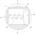
FIG. 1 is a schematic front sectional view of the present invention;
FIG. 2 is a schematic front sectional view of the kneading plate according to the present invention;
FIG. 3 is a schematic sectional view of the twisting plate according to the present invention;
FIG. 4 is a schematic view of the movable roller of the present invention after moving;
FIG. 5 is a schematic top view of the present invention;
FIG. 6 is a schematic cross-sectional view taken at A in FIG. 1 according to the present invention;
FIG. 7 is a schematic view of a front cross-sectional view of the connecting shaft of the present invention;
FIG. 8 is a schematic view of a front cross-sectional structure of the storage case of the present invention;
FIG. 9 is a schematic diagram of the moved magazine according to the present invention.
In the figure: 1. a processing table; 2. a support frame; 3. an electric motor; 4. a connecting shaft; 5. twisting the plate; 6. a protective pad; 7. a movable groove; 8. a movable roller; 9. adjusting a rod; 10. a worm; 11. a worm gear; 12. a movable barrel; 13. a connecting rod; 14. a guide block; 15. a storage box; 16. fixing grooves; 17. fixing the rod; 18. a return spring; 19. a piston block; 20. a fixed cavity; 21. a gas delivery pipe; 22. connecting the sleeve blocks; 23. a fixing hole; 24. fixing the tube; 25. an air outlet; 26. a first magnet; 27. a second magnet; 28. a movable rod; 29. a piston plate; 30. a connecting cavity; 31. a gas transmission channel; 32. a connecting hose; 33. an air outlet nozzle.
Detailed Description
The technical solutions in the embodiments of the present invention will be clearly and completely described below with reference to the drawings in the embodiments of the present invention, and it is obvious that the described embodiments are only a part of the embodiments of the present invention, and not all of the embodiments. All other embodiments, which can be derived by a person skilled in the art from the embodiments given herein without making any creative effort, shall fall within the protection scope of the present invention.
Referring to fig. 1-9, the present invention provides a technical solution: a green tea processing kneading machine with adjustable force is provided with a processing table 1, a supporting frame 2 is fixed at the upper edge of the processing table 1, a motor 3 is installed at the top of the supporting frame 2 through a bolt, an output shaft of the motor 3 is mutually connected with the top of a connecting shaft 4 through a belt pulley mechanism, and a bearing of the connecting shaft 4 penetrates through the inside of the supporting frame 2; the method comprises the following steps: the kneading plate 5 is fixedly installed at the bottom of the connecting shaft 4, a rubber protective pad 6 is adhered to the lower end face of the kneading plate 5, a movable groove 7 is formed in the kneading plate 5, a movable roller 8 is movably arranged in the movable groove 7, an adjusting rod 9 movably penetrates through the side face of the kneading plate 5, a worm 10 is fixedly sleeved at one end, close to the kneading plate 5, of the adjusting rod 9, and a worm wheel 11 is meshed with the side of the worm 10; the storage box 15 is movably arranged inside the processing table 1, a fixing groove 16 is formed in the processing table 1 on the outer side of the storage box 15, a fixing rod 17 is fixed on the side face of the storage box 15, and a return spring 18 is wound on the outer side of the fixing rod 17; the first magnet 26 is fixed at the bottom of the storage box 15, the second magnet 27 is movably arranged below the first magnet 26, the lower end face of the second magnet 27 is fixed with a movable rod 28, the other return spring 18 is wound on the outer side of the movable rod 28, the bottom of the movable rod 28 is connected with a piston plate 29, and a connecting cavity 30 is formed in the processing table 1 on the outer side of the piston plate 29.
As shown in fig. 1-4, the movable roller 8 and the rolling plate 5 form a longitudinal sliding structure through the movable groove 7, and the movable roller 8 is symmetrically distributed about the vertical axis of the rolling plate 5, and the bottom of the movable roller 8 contacts with the upper surface of the protection pad 6, and the rolling plate 5 is eccentrically arranged about the center of the storage box 15; a movable cylinder 12 is fixedly penetrated through the interior of the worm wheel 11, two ends of the movable cylinder 12 are in threaded connection with a connecting rod 13, and one end of the connecting rod 13, which is far away from the movable cylinder 12, is fixedly provided with a guide block 14; one side of the guide block 14 close to the movable roller 8 is provided with an inclined plane, the inclined plane of the guide block 14 is in contact with the top of the movable roller 8, and the moving directions of the 2 guide blocks 14 are opposite, when the kneading force needs to be adjusted, the worm 10 can be driven to synchronously rotate by rotating the adjusting rod 9, then the movable cylinder 12 is driven to rotate by meshing with the worm wheel 11, the 2 guide blocks 14 can be driven to mutually approach or separate from each other by virtue of threaded connection between the movable cylinder 12 and the connecting rod 13, the movable roller 8 can be pushed to slide downwards in the movable groove 7 when the movable roller 8 separates from the connecting rod, and then the protective pad 6 below the movable roller is pushed to bulge, so that the distance between the protective pad 6 below the movable roller 8 and tea leaves is reduced, the kneading force is further improved, and when the movable roller 8 does not need to be adjusted, the adjusting rod 9 can be rotated reversely, so that the movable roller 8 can be driven to upwards move by the resilience of the protective pad 6, the lower surface of the kneading plate 5 is in a planar state, and further planar kneading is realized, and the kneading force can be satisfied with the kneading requirements of different kneading forces;
as shown in fig. 1 and 5, the storage box 15 and the processing table 1 form a horizontal relative movement structure through a fixing groove 16, and the fixing rod 17 and the processing table 1 are slidably connected with one end of the fixing rod 17 away from the storage box 15 and are fixed with a piston block 19, and a fixing cavity 20 is formed in the processing table 1 outside the piston block 19, after the required kneading force is adjusted, the motor 3 drives the connecting shaft 4 to rotate through a pulley mechanism, so as to drive the kneading plate 5 to rotate in the storage box 15 to knead the tea leaves, when the kneading plate 5 rotates and contacts with the left end of the storage box 15, the storage box 15 can be pushed to move in the fixing groove 16 and drive the fixing rod 17 to slide on the processing table 1, and when the kneading plate 5 does not push the storage box 15, the storage box 15 can be restored to the original position through the resilience of the return spring 18, so that the reciprocating horizontal movement of the storage box 15 can be realized through the continuous rotation of the kneading plate 5, the uniformity of the distribution of the tea leaves in the storage box 15 is improved, and the kneading performance of the whole area is improved;
as shown in fig. 1 and fig. 6-7, the top of the fixed cavity 20 is communicated with one end of the air pipe 21, the other end of the air pipe 21 is fixed with a connecting sleeve block 22, the connecting sleeve block 22 is sleeved outside the connecting shaft 4, the connecting sleeve block 22 is rotatably connected with the connecting shaft 4, when the storage box 15 moves leftwards, the fixed rod 17 and the piston block 19 are driven to move leftwards, and when the storage box 15 is not pushed, the piston block 19 can be driven to rapidly move rightwards through the resilience of the return spring 18, and the air in the fixed cavity 20 is pushed into the air pipe 21; the connecting sleeve block 22 is communicated with the connecting shaft 4 through a fixing hole 23, the fixing hole 23 is formed in the surface of the connecting shaft 4 on the inner side of the connecting sleeve block 22, the side face of the lower end of the connecting shaft 4 is communicated with the inside of the rolling plate 5 through a fixing pipe 24, an air outlet 25 is reserved in the center of the lower surface of the rolling plate 5, air in the air conveying pipe 21 can enter the connecting shaft 4 through the fixing hole 23, the connecting sleeve block 22 cannot interfere with rotation of the connecting shaft 4, then the air enters the rolling plate 5 through the fixing pipe 24 and is discharged from the air outlet 25 and blown to the surface of rolled tea leaves, redundant moisture on the surface of the tea leaves after enzyme deactivation can be removed, the redundant moisture can be removed synchronously in the rolling process, and additional air conveying equipment does not need to be used;
as shown in fig. 1 and fig. 8-9, the first magnet 26 and the second magnet 27 are homopolar magnets, the second magnet 27 forms a longitudinal sliding structure with the processing table 1 through the movable rod 28, and the edge of the piston plate 29 is in fit sliding with the inner wall of the connecting cavity 30; the connecting cavity 30 is communicated with the connecting hose 32 through the gas transmission channel 31, the gas transmission channel 31 is arranged inside the processing table 1, and two ends of the connecting hose 32 are respectively connected with the inner corner of the fixing groove 16 and the outer corner of the storage box 15; the connecting hose 32 is communicated with the air outlet nozzle 33 through the storage box 15, the air outlet nozzle 33 is fixed on the inner wall of the storage box 15 at an equal angle, the outer diameter of the storage box 15 is smaller than the length of the fixing groove 16, after the storage box 15 moves leftwards, the first magnet 26 and the second magnet 27 are driven to be staggered, the second magnet 27 is not subjected to repulsive force, the second magnet 27 can be driven to move upwards through resilience of the reset spring 18, the storage box 15 drives the first magnet 26 to move right above the second magnet 27, the second magnet 27 can be driven to move downwards through repulsion between the first magnet and the second magnet, the piston plate 29 is driven to synchronously move downwards through the movable rod 28, air in the connecting cavity 30 is pushed into the air conveying channel 31, in the moving process of the storage box 15, the air can also enter the storage box 15 through the connecting hose 32 and finally is discharged from the air outlet nozzle 33, tea leaves at the edge of the storage box 15 are blown towards the center of the storage box, a dead zone of kneading is avoided, and uniformity of the kneading is further improved.
The working principle is as follows: as shown in fig. 1-9, tea leaves to be kneaded are placed in a storage box 15, then the height of the movable roller 8 is adjusted according to the quantity of the tea leaves and the force to be kneaded, after the movable roller 8 descends, the protective pad 6 can be pushed to be in a convex state, so that kneading with different forces is realized, and in the kneading process, the tea leaves can be dried by blown gas, and the storage box 15 moves horizontally, so that the uniformity of tea leaf distribution is improved;
utilize the repellent nature of magnet to produce gas simultaneously, gas blows to tealeaves from gas outlet nozzle 33, the homogeneity that promotes tealeaves and distribute that can step forward avoids tealeaves to pile up the comprehensive nature that influences the kneading at 15 edges of storage box.
Although the present invention has been described in detail with reference to the foregoing embodiments, it will be apparent to those skilled in the art that modifications may be made to the embodiments described in the foregoing embodiments, or equivalents may be substituted for elements thereof.
Claims (10)
1. A green tea processing kneading machine with adjustable force is provided with a processing table (1), a supporting frame (2) is fixed at the upper edge of the processing table (1), a motor (3) is mounted at the top of the supporting frame (2) through a bolt, an output shaft of the motor (3) is mutually connected with the top of a connecting shaft (4) through a belt pulley mechanism, and a bearing of the connecting shaft (4) penetrates through the inside of the supporting frame (2);
it is characterized by comprising:
the rubber protective pad is adhered to the lower end face of the rolling plate (5), a movable groove (7) is formed in the rolling plate (5), a movable roller (8) is movably arranged in the movable groove (7), an adjusting rod (9) movably penetrates through the side face of the rolling plate (5), a worm (10) is fixedly sleeved at one end, close to the rolling plate (5), of the adjusting rod (9), and a worm wheel (11) is meshed with the side of the worm (10);
the storage box (15) is movably arranged inside the processing table (1), a fixing groove (16) is formed in the processing table (1) on the outer side of the storage box (15), a fixing rod (17) is fixed on the side face of the storage box (15), and a return spring (18) is wound on the outer side of the fixing rod (17);
first magnet (26), be fixed in the bottom of storage box (15), the below activity of first magnet (26) is provided with second magnet (27), and the lower terminal surface of second magnet (27) is fixed with movable rod (28) to the outside of movable rod (28) is twined there is another reset spring (18), the bottom of movable rod (28) is connected with piston plate (29), and has seted up in processing platform (1) in the piston plate (29) outside and has connected chamber (30).
2. The adjustable strength kneading machine for green tea processing according to claim 1, wherein: the movable roller (8) forms a longitudinal sliding structure through the movable groove (7) and the rolling plate (5), the movable roller (8) is symmetrically distributed about the vertical axis of the rolling plate (5), the bottom of the movable roller (8) is in contact with the upper surface of the protective pad (6), and the rolling plate (5) is eccentrically arranged about the circle center of the storage box (15).
3. The adjustable strength kneading machine for green tea processing according to claim 1, wherein: the inside of worm wheel (11) is fixed to run through has a movable cylinder (12), and the both ends threaded connection of movable cylinder (12) has connecting rod (13) to the one end that movable cylinder (12) was kept away from in connecting rod (13) is fixed with guide block (14).
4. The adjustable strength kneading machine for green tea processing according to claim 3, wherein: one side of the guide block (14) close to the movable roller (8) is arranged as an inclined plane, the inclined plane of the guide block (14) is in contact with the top of the movable roller (8), and the moving directions of the 2 guide blocks (14) are opposite.
5. The adjustable strength kneading machine for green tea processing according to claim 1, wherein: the storage box (15) forms a horizontal relative movement structure through the fixing groove (16) and the processing table (1), the fixing rod (17) and the processing table (1) are fixedly provided with a piston block (19) for slidably connecting one end, far away from the storage box (15), of the fixing rod (17), and a fixing cavity (20) is formed in the processing table (1) on the outer side of the piston block (19).
6. The adjustable strength kneading machine for green tea processing according to claim 5, wherein: the top of fixed chamber (20) and the one end of gas-supply pipe (21) communicate each other, and the other end of gas-supply pipe (21) is fixed with and connects set piece (22) to connect set piece (22) cover to establish the outside at connecting axle (4), connect set piece (22) and connecting axle (4) simultaneously and be connected for rotating.
7. The adjustable strength kneading machine for green tea processing according to claim 6, wherein: connecting sleeve piece (22) are linked together through fixed orifices (23) and connecting axle (4), and fixed orifices (23) set up on connecting axle (4) surface of connecting sleeve piece (22) inboard to the lower extreme side of connecting axle (4) is through fixed pipe (24) and knead the inside of twisting board (5) and communicate each other, kneads the lower surface center department of twisting board (5) simultaneously and reserves exhaust vent (25).
8. The adjustable strength kneading machine for green tea processing according to claim 1, wherein: first magnet (26) and second magnet (27) are homopolar magnet, and second magnet (27) pass through movable rod (28) and processing platform (1) and constitute fore-and-aft sliding structure, the edge of piston plate (29) and the inner wall laminating of connecting chamber (30) slide.
9. The adjustable strength kneading machine for green tea processing according to claim 1, wherein: the connecting cavity (30) is communicated with the connecting hose (32) through the gas transmission channel (31), the gas transmission channel (31) is arranged inside the processing table (1), and two ends of the connecting hose (32) are respectively connected with the inner corner of the fixing groove (16) and the outer corner of the storage box (15).
10. The adjustable strength green tea processing rolling machine according to claim 9, wherein: the connecting hose (32) is communicated with the air outlet nozzle (33) through the storage box (15), the air outlet nozzle (33) is fixed on the inner wall of the storage box (15) at equal angles, and the outer diameter of the storage box (15) is smaller than the length of the fixing groove (16).
Priority Applications (1)
| Application Number | Priority Date | Filing Date | Title |
|---|---|---|---|
| CN202211180491.3A CN115633723A (en) | 2022-09-26 | 2022-09-26 | Green tea processing of adjustable dynamics is with rolling machine |
Applications Claiming Priority (1)
| Application Number | Priority Date | Filing Date | Title |
|---|---|---|---|
| CN202211180491.3A CN115633723A (en) | 2022-09-26 | 2022-09-26 | Green tea processing of adjustable dynamics is with rolling machine |
Publications (1)
| Publication Number | Publication Date |
|---|---|
| CN115633723A true CN115633723A (en) | 2023-01-24 |
Family
ID=84941791
Family Applications (1)
| Application Number | Title | Priority Date | Filing Date |
|---|---|---|---|
| CN202211180491.3A Pending CN115633723A (en) | 2022-09-26 | 2022-09-26 | Green tea processing of adjustable dynamics is with rolling machine |
Country Status (1)
| Country | Link |
|---|---|
| CN (1) | CN115633723A (en) |
Cited By (1)
| Publication number | Priority date | Publication date | Assignee | Title |
|---|---|---|---|---|
| CN115918747A (en) * | 2023-02-03 | 2023-04-07 | 安徽绿月茶业有限公司 | Black tea processing is with rolling device in succession |
Citations (8)
| Publication number | Priority date | Publication date | Assignee | Title |
|---|---|---|---|---|
| GB475642A (en) * | 1936-07-23 | 1937-11-23 | Brooke Bond & Company Ltd | Improvements in or relating to machines for cutting manufactured tea and like dry substances |
| CN206005807U (en) * | 2016-07-26 | 2017-03-15 | 金溪百士利实业有限公司 | A kind of adjustable tea rolling device |
| CN108634043A (en) * | 2018-03-29 | 2018-10-12 | 杭州知加网络科技有限公司 | A kind of tea processing device of tea rolling |
| CN208318143U (en) * | 2017-10-18 | 2019-01-04 | 寻乌县甘霖阳天茶业有限公司 | It is a kind of to rub the controllable tea rolling device of dynamics |
| CN208925140U (en) * | 2018-08-23 | 2019-06-04 | 兴宁富荣实业有限公司 | A kind of quick twisting device of tea twisting machine |
| CN110810569A (en) * | 2019-12-07 | 2020-02-21 | 安徽任山云峰绿茶有限公司 | Green tea processing is with rolling equipment |
| CN211721740U (en) * | 2019-12-30 | 2020-10-23 | 珙县僰贡茶业有限公司 | Black tea processing is with rolling device that completes |
| CN112889957A (en) * | 2021-03-02 | 2021-06-04 | 拓太(广州)实业有限公司 | Tea processing system |
-
2022
- 2022-09-26 CN CN202211180491.3A patent/CN115633723A/en active Pending
Patent Citations (8)
| Publication number | Priority date | Publication date | Assignee | Title |
|---|---|---|---|---|
| GB475642A (en) * | 1936-07-23 | 1937-11-23 | Brooke Bond & Company Ltd | Improvements in or relating to machines for cutting manufactured tea and like dry substances |
| CN206005807U (en) * | 2016-07-26 | 2017-03-15 | 金溪百士利实业有限公司 | A kind of adjustable tea rolling device |
| CN208318143U (en) * | 2017-10-18 | 2019-01-04 | 寻乌县甘霖阳天茶业有限公司 | It is a kind of to rub the controllable tea rolling device of dynamics |
| CN108634043A (en) * | 2018-03-29 | 2018-10-12 | 杭州知加网络科技有限公司 | A kind of tea processing device of tea rolling |
| CN208925140U (en) * | 2018-08-23 | 2019-06-04 | 兴宁富荣实业有限公司 | A kind of quick twisting device of tea twisting machine |
| CN110810569A (en) * | 2019-12-07 | 2020-02-21 | 安徽任山云峰绿茶有限公司 | Green tea processing is with rolling equipment |
| CN211721740U (en) * | 2019-12-30 | 2020-10-23 | 珙县僰贡茶业有限公司 | Black tea processing is with rolling device that completes |
| CN112889957A (en) * | 2021-03-02 | 2021-06-04 | 拓太(广州)实业有限公司 | Tea processing system |
Cited By (2)
| Publication number | Priority date | Publication date | Assignee | Title |
|---|---|---|---|---|
| CN115918747A (en) * | 2023-02-03 | 2023-04-07 | 安徽绿月茶业有限公司 | Black tea processing is with rolling device in succession |
| CN115918747B (en) * | 2023-02-03 | 2024-08-30 | 南涧县黑龙潭茶业有限公司 | Continuous rolling device for black tea processing |
Similar Documents
| Publication | Publication Date | Title |
|---|---|---|
| CN115633723A (en) | Green tea processing of adjustable dynamics is with rolling machine | |
| CN102771528B (en) | Cut steamed bun making machine | |
| CN210334531U (en) | Efficient cutting device is used in battenboard processing | |
| CN113910615B (en) | Wood-plastic composite section molding press-fit device and press-fit method | |
| CN212711572U (en) | Machining circulation feed machine | |
| CN210651882U (en) | Film pasting device for fireproof plate production | |
| CN216796450U (en) | Material guide device for tobacco shred production | |
| CN217703812U (en) | Segmentation cutting device of mao bamboo raw materials | |
| CN210391790U (en) | Material shaping unloader | |
| CN208378909U (en) | A kind of pressuring flat device of leather | |
| CN202773926U (en) | Steamed bun cutting machine | |
| CN115256887A (en) | Board thermal extrusion back shaping device is moulded to PVC wood | |
| CN108527596A (en) | A kind of timber processing shaping equipment | |
| CN213797010U (en) | Automatic discharging plate cutting machine for furniture processing | |
| CN210418449U (en) | Electric vertical lifting feeding machine | |
| CN215391839U (en) | Corrugated plate pressing and arcing machine | |
| CN218551115U (en) | Moon cake forming machine | |
| CN217894044U (en) | Even stone device of sheet machine is used in production of plastics tray | |
| CN216065131U (en) | Roll-in production system for anti-seismic support | |
| CN219296785U (en) | Production and processing paper cutting blanking assembly | |
| CN216271785U (en) | Material feeding unit is divided in feed arrangement to material ball of pumpkin cake cooked flake wrapping machine | |
| CN221292209U (en) | Shaping tractor is used in extruded sheet production | |
| CN115740301A (en) | Bearing ball extrusion forming equipment and process thereof | |
| CN219189821U (en) | Ceramic fiber board turn-over device | |
| CN214719391U (en) | Multi-dimensional cold rolling forming device for fire-proof rolling door |
Legal Events
| Date | Code | Title | Description |
|---|---|---|---|
| PB01 | Publication | ||
| PB01 | Publication | ||
| SE01 | Entry into force of request for substantive examination | ||
| SE01 | Entry into force of request for substantive examination |