CN115538678A - Construction method for large-angle overhanging landscape platform side small platform - Google Patents
Construction method for large-angle overhanging landscape platform side small platform Download PDFInfo
- Publication number
- CN115538678A CN115538678A CN202211312630.3A CN202211312630A CN115538678A CN 115538678 A CN115538678 A CN 115538678A CN 202211312630 A CN202211312630 A CN 202211312630A CN 115538678 A CN115538678 A CN 115538678A
- Authority
- CN
- China
- Prior art keywords
- die
- platform
- overhanging
- encorbelmenting
- rod
- Prior art date
- Legal status (The legal status is an assumption and is not a legal conclusion. Google has not performed a legal analysis and makes no representation as to the accuracy of the status listed.)
- Granted
Links
Images


Classifications
-
- E—FIXED CONSTRUCTIONS
- E04—BUILDING
- E04B—GENERAL BUILDING CONSTRUCTIONS; WALLS, e.g. PARTITIONS; ROOFS; FLOORS; CEILINGS; INSULATION OR OTHER PROTECTION OF BUILDINGS
- E04B5/00—Floors; Floor construction with regard to insulation; Connections specially adapted therefor
- E04B5/43—Floor structures of extraordinary design; Features relating to the elastic stability; Floor structures specially designed for resting on columns only, e.g. mushroom floors
-
- E—FIXED CONSTRUCTIONS
- E04—BUILDING
- E04G—SCAFFOLDING; FORMS; SHUTTERING; BUILDING IMPLEMENTS OR AIDS, OR THEIR USE; HANDLING BUILDING MATERIALS ON THE SITE; REPAIRING, BREAKING-UP OR OTHER WORK ON EXISTING BUILDINGS
- E04G11/00—Forms, shutterings, or falsework for making walls, floors, ceilings, or roofs
- E04G11/36—Forms, shutterings, or falsework for making walls, floors, ceilings, or roofs for floors, ceilings, or roofs of plane or curved surfaces end formpanels for floor shutterings
- E04G11/365—Stop-end shutterings
-
- E—FIXED CONSTRUCTIONS
- E04—BUILDING
- E04G—SCAFFOLDING; FORMS; SHUTTERING; BUILDING IMPLEMENTS OR AIDS, OR THEIR USE; HANDLING BUILDING MATERIALS ON THE SITE; REPAIRING, BREAKING-UP OR OTHER WORK ON EXISTING BUILDINGS
- E04G11/00—Forms, shutterings, or falsework for making walls, floors, ceilings, or roofs
- E04G11/36—Forms, shutterings, or falsework for making walls, floors, ceilings, or roofs for floors, ceilings, or roofs of plane or curved surfaces end formpanels for floor shutterings
- E04G11/48—Supporting structures for shutterings or frames for floors or roofs
-
- E—FIXED CONSTRUCTIONS
- E04—BUILDING
- E04G—SCAFFOLDING; FORMS; SHUTTERING; BUILDING IMPLEMENTS OR AIDS, OR THEIR USE; HANDLING BUILDING MATERIALS ON THE SITE; REPAIRING, BREAKING-UP OR OTHER WORK ON EXISTING BUILDINGS
- E04G17/00—Connecting or other auxiliary members for forms, falsework structures, or shutterings
Abstract
The application relates to the technical field of construction of platforms on the outer sides of buildings, and provides a construction method for a large-angle overhanging landscape platform side small platform, which comprises the following steps of S1: embedding and fixing the stiff skeleton: embedding a stiff skeleton on an upright post in a building, wherein the stiff skeleton comprises a longitudinal rod, one end of the longitudinal rod is fixed with a steel reinforcement cage in the upright post, one end of the longitudinal rod, which is far away from the upright post, extends out of a lighting hole, and one end of the longitudinal rod, which is far away from the upright post, is vertically fixed with a transverse rod; s2: erecting a hanging mould assembly on a floor slab at the top layer of the building, and hanging bottom moulds of the viewing platform and the corridor at the bottoms of the overhanging sections of the transverse rods and the longitudinal rods through the hanging mould assembly; s3: binding reinforcing meshes of the lateral small platforms and the vestibule at the peripheries of the overhanging ends of the transverse rods and the longitudinal rods; s4: a side die is supported on the periphery of the bottom die; s5: pouring concrete into a die cavity formed by the bottom die and the side die and curing; s6: and removing the side die and the bottom die. This application has the effect that promotes little platform bearing capacity in side.
Description
Technical Field
The application relates to the technical field of construction of platforms outside buildings, in particular to a construction method of a small platform on the side surface of a large-angle overhanging landscape platform.
Background
According to actual design requirements, as shown in fig. 1, overhanging viewing platforms and side small platforms 16 need to be arranged on two adjacent sides of a building respectively, each overhanging viewing platform comprises an ascending part, a descending part 12 and an overhanging platform 1 used for connecting the ascending part with the descending part 12, the ascending part comprises an indoor section 13 and an overhanging section 11, and the outdoor section is connected with the overhanging section 11 through a horizontal bearing platform 14. Meanwhile, the building outer wall provided with the small side platform 16 is provided with a lighting hole 17, the lighting hole 17 is opposite to the horizontal bearing platform 14, and the small side platform 16 is connected with the horizontal bearing platform 14 through a corridor 15, so that personnel can conveniently enter the small side platform 16 through the corridor 15.
At present, when a side view table is actually constructed, a steel bar mesh is usually connected with a reserved steel bar joint of an outer wall of a building when a side small platform is constructed, when the side view table is used subsequently, loads are all concentrated at the steel bar mesh of the side small platform and the reserved steel bar joint of the outer wall of the building, the bearing capacity of the side small platform is insufficient, the side small platform is prone to downward disturbance and deformation, and certain potential safety hazards exist.
Disclosure of Invention
In order to improve the overall strength and the bearing capacity of the small side platform, the application provides a construction method of the small side platform of the large-angle overhanging landscape platform.
The application provides a construction method for a large-angle overhanging landscape platform side small platform, which adopts the following technical scheme:
a construction method of a large-angle overhanging landscape platform side small platform comprises the following steps,
s1: embedding and fixing the stiff skeleton: pre-burying a stiff skeleton on an upright post in a building, wherein the stiff skeleton comprises a longitudinal rod, one end of the longitudinal rod is fixed with a reinforcement cage in the upright post, one end of the longitudinal rod, which is far away from the upright post, extends out of a lighting hole, and one end of the longitudinal rod, which is far away from the upright post, is vertically fixed with a transverse rod;
s2: erecting a hanging mould assembly on a floor slab at the top layer of the building, and hanging bottom moulds of the viewing platform and the corridor at the bottoms of the overhanging sections of the transverse rods and the longitudinal rods through the hanging mould assembly;
s3: binding reinforcing meshes of the lateral small platforms and the vestibule at the peripheries of the overhanging ends of the transverse rods and the longitudinal rods;
s4: a side die is supported on the periphery of the bottom die;
s5: pouring concrete into a die cavity formed by the bottom die and the side die and curing;
s6: and (5) dismantling the side die and the bottom die to finish the construction of the side small platform and the corridor.
Through adopting above-mentioned technical scheme, this application is through pre-buried strength nature skeleton to at both reinforcing bar nets of horizontal pole and longitudinal rod periphery ligature side platform and vestibule of strength nature skeleton, follow-up vestibule and the little platform construction of side are accomplished the back, alright carry out the auxiliary stay to vestibule and the little platform reinforcing bar net in side through strength nature skeleton, compare between traditional side platform and the building only through reinforcing bar net with reserve the bar connection and carry out the connected mode, be favorable to improving the atress condition of side platform and vestibule through strength nature skeleton, and then promote the bearing capacity and the bulk strength of side platform and vestibule.
Preferably, hang the mould subassembly including setting up a plurality of I-beams of encorbelmenting at the top layer floor, the one end of encorbelmenting the I-beam is fixed at the top layer floor through a plurality of anchor assembly, the other end of encorbelmenting the I-beam stretches out the top layer floor and forms the end of encorbelmenting outward, the I-beam of encorbelmenting be provided with the connecting rod between end and the die block, the connecting rod both ends can be dismantled respectively and connect between the die block and the I-beam of encorbelmenting.
Through adopting above-mentioned technical scheme, prop up and establish before the die block, fix a plurality of I-beams of encorbelmenting on the top layer floor through anchor assembly, the rethread connecting rod hangs the die block and connects in both bottoms of transverse bar and longitudinal rod, alright realize propping up of die block and establish, it is more convenient to compare the tradition and need set up the mode that falls to the ground full hall scaffold frame as the die block support when establishing the die block, has reduced the use of a large amount of steel pipe fittings for prop up of die block and establish more simple and convenient.
Preferably, the I-beam and the die block of encorbelmenting are worn to locate respectively at the connecting rod both ends, there is lock nut at the connecting rod both ends difference threaded connection, the lock nut at connecting rod both ends respectively the butt in the one side that I-beam and die block deviate from each other encorbelments, I-beam and the die block of encorbelmenting all set up the through-hole that supplies the connecting rod to wear to establish.
Through adopting above-mentioned technical scheme, during the installation die block, articulate the connecting rod top segment through a set of lock nut and after encorbelment the end on the I-beam of encorbelmenting, remove the die block, wear to locate the through-hole that corresponds on the die block until the connecting rod bottom, with another set of lock nut screw in connecting rod bottom again, utilize the lock nut of connecting rod bottom to hold up the die block, alright realize propping up the die block in both bottoms of longitudinal rod and transverse bar. When the bottom die is subsequently disassembled, the bottom die can be disassembled from the bottom of the small platform on the side face only by screwing out the locking nut at the bottom end of the connecting rod, so that the bottom die plate is convenient to disassemble and assemble.
Preferably, in S1, a plurality of support rods are embedded in the outer wall of the building before the rigid framework is embedded, and the bottoms of the transverse rods are lapped on the plurality of support rods when the rigid framework is constructed.
By adopting the technical scheme, the transverse rods of the stiff skeleton are supported by the pre-embedded support rods conveniently through the arrangement of the support rods, so that the transverse rods are not easy to bend and deform, the overall structural strength of the stiff skeleton is convenient to improve, and the whole of the side small platform is convenient to be improved better through the stiff skeleton
Preferably, the longitudinal rod penetrates through a horizontal bearing platform of the upper ladder part.
By adopting the technical scheme, on one hand, the horizontal bearing platform is utilized to provide a fulcrum for the longitudinal rod, so that the longitudinal rod is not easy to deform under stress, and the stiff framework is convenient to better reinforce the small platform on the side surface; meanwhile, the horizontal bearing platform can be reinforced through the longitudinal rods, so that the horizontal bearing platform of the upper ladder part is more stable.
Preferably, the connecting rod is further coaxially sleeved with a plurality of sleeving pipes, and the bottom ends of the sleeving pipes abut against the upper surface of the bottom die.
Through adopting above-mentioned technical scheme, through the setting of bell and spigot joint pipe, follow-up side direction is seen the scenery layer platform and is pour and accomplish the back, back is twisted out the nut at connecting rod both ends, alright demolish the connecting rod from the little platform of side, the turnover of the connecting rod of being convenient for is used.
Preferably, the anchoring part includes pre-buried two sets of gag lever post at the top floor, the I-beam of encorbelmenting is located between two sets of gag lever posts, the anchoring part still sets up the clamp plate at the I-beam top, the clamp plate corresponds two sets of gag lever posts and has seted up two sets of perforation, the clamp plate is established on two sets of gag lever posts through two sets of perforation covers, and is two sets of the equal threaded connection in gag lever post top has stop nut, stop nut supports tightly with one side that the clamp plate deviates from the I-beam of encorbelmenting.
Through adopting above-mentioned technical scheme, when the fixed I-beam that encorbelments, with between two sets of gag lever posts of bracing piece, establish the clamp plate cover at two sets of gag lever posts tops, with lock nut screw in gag lever post top alright realize fixing the I-beam that encorbelments on the top floor, the I-beam dismouting of encorbelmenting in the top floor of being convenient for.
Preferably, a sealing tape is bonded at the joint of the sleeve and the bottom die.
By adopting the technical scheme, through the setting of sealing strip, utilize the clearance between sealing strip shutoff bell and spigot joint pipe and the die block, when being favorable to reducing toward die block concreting, the concrete is through the condition that clearance infiltration cup jointed intraductal between bell and spigot joint pipe and the die block, and the follow-up connecting rod edgewise trawl of being convenient for is taken out.
In summary, the present application includes at least one of the following beneficial technical effects:
1. the stiff framework is pre-buried on the stand columns, the steel bars of the side small platforms and the coupling beams are bound on the peripheries of the transverse rods and the longitudinal rods of the stiff framework, after the subsequent construction of the side small platforms and the construction of the corridor are completed, the longitudinal rods and the transverse rods can be used as the frameworks of the steel bar nets of the side small platforms and the corridor, the overall strength of the side small platforms and the corridor is improved, meanwhile, the side small platforms are supported in an auxiliary mode through the stiff framework, the overall bearing capacity of the side small platforms is improved, the overall stress condition of the joints of the side small platforms and the building outer wall is improved, and the side small platforms and the corridor are not prone to downward disturbance and deformation.
2. The supporting rods are fixed on the building outer wall in a pre-buried mode, the transverse rods are connected to the supporting rods in an overlapping mode, the transverse rods are supported through the supporting rods, and the transverse rods are not prone to stress deformation.
3. Wear to locate the setting of horizontal cushion cap through vertical pole, carry out the auxiliary stay through horizontal cushion cap to vertical pole on the one hand for vertical pole is difficult for the atress to be out of shape, still can promote the bulk strength of horizontal cushion cap through vertical pole simultaneously.
Drawings
FIG. 1 is a schematic view of the present embodiment showing the overhanging end of the upstairs portion, the indoor section of the upstairs portion, and the horizontal bearing platform; the position schematic diagrams of the overhanging landscape platform, the lower ladder part, the lateral small platform, the corridor, the upright post and the lighting hole.
Fig. 2 is a schematic view illustrating a state in which the bottom mold is erected according to the present embodiment.
Fig. 3 is a schematic diagram illustrating the state of the embodiment when the reinforcing mesh is bound
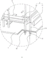
Fig. 4 is an enlarged schematic view of a portion a in fig. 2.
Fig. 5 is an enlarged schematic view of a portion B in fig. 2.
Description of the reference numerals:
1. a cantilever platform; 10. a column; 11. a cantilever section; 12. a lower ladder section; 13. an indoor section; 14. a horizontal bearing platform; 15. a corridor; 16. a small platform on the side; 17. lighting holes; 18. a top floor slab; 2. a stiff skeleton; 21. a longitudinal rod; 22. a transverse bar; 3. an overhanging I-beam; 31. a connecting rod; 311. sleeving a pipe; 32. locking the nut; 33. an anti-drop nut; 4. bottom die; 41. side mould; 5. a support bar; 6. a limiting rod; 61. pressing a plate; 62. and a limiting nut.
Detailed Description
The present application is described in further detail below with reference to figures 1-5.
Referring to fig. 1, in this embodiment, the landscape architecture platform of encorbelmenting is located the adjacent both sides of building with the little platform 16 in side, the landscape architecture platform of encorbelmenting includes ladder portion, lower ladder portion 12 and be used for connecting the platform 1 of encorbelmenting of ladder portion and lower ladder portion 12, ladder portion is including being located the inside indoor section 13 of building and stretching out the section 11 of encorbelmenting outside the building, indoor section 13 links up through horizontal cushion cap 14 with the section 11 of encorbelmenting, the building has been provided with lighting hole 17 in the outer wall of little platform 16 one side in side, horizontal cushion cap 14 is connected through vestibule 15 with little platform 16 in side, be provided with stand 10 in the building, stand 10 is located one side that horizontal cushion cap 14 deviates from lighting hole 17 and stand 10 sets up with horizontal cushion cap 14 relatively.
The embodiment of the application discloses a construction method of a large-angle overhanging landscape platform side small platform 16, which refers to fig. 2 and 3 and comprises the following steps:
s1: embedding and fixing the stiff skeleton 2: and (3) embedding and fixing the stiff frameworks 2 on the internal upright columns 10 of the building.
The stiff skeleton 2 comprises a longitudinal rod 21, one end of the longitudinal rod 21 is fixed with a reinforcement cage of the upright post 10, one end of the longitudinal rod 21, which is far away from the upright post 10, penetrates through the horizontal bearing platform 14 and extends out of the lighting hole 17, one end of the longitudinal rod 21, which extends out of the lighting hole 17, is also fixedly welded with a transverse rod 22, the longitudinal rod 21 and the transverse rod 22 are vertically arranged, and in the embodiment, the longitudinal rod 21 and the transverse rod 22 are I-shaped beams. The connecting part of the longitudinal rod 21 and the transverse rod 22 is also welded and fixed with a diagonal brace, and the connecting strength of the longitudinal rod 21 and the diagonal brace is improved through the diagonal brace.
One end of the longitudinal rod 21 far away from the upright post 10 penetrates through the horizontal bearing platform 14, on one hand, the horizontal bearing platform 14 is used for providing a fulcrum, so that the longitudinal rod 21 is not easy to deform under stress, and on the other hand, the horizontal bearing platform 14 can be reinforced through the upright post 10 to improve the overall structural strength of the horizontal bearing platform 14.
In S1, before constructing a stiff framework 2, a plurality of support rods 5 are pre-embedded in the outer wall of the building, in the embodiment, the support rods 5 are I-shaped beams, and the support rods 5 are welded and fixed with a reinforcing mesh in the outer wall of the building; when the stiff framework 2 is constructed, the transverse rods 22 of the stiff framework 2 are lapped on the plurality of support rods 5 to realize auxiliary support of the transverse rods 22, so that the transverse rods 22 can more stably support the reinforcing mesh of the small side platform 16, and the bearing capacity and the overall strength of the small side platform 16 can be better improved through the stiff framework 2.
S2: erecting a hanging mould assembly on a floor slab on the top side of the building, and hanging and connecting the bottom moulds 4 of the landscape platform and the corridor 15 at the bottoms of the overhanging sections 11 of the transverse rods 22 and the longitudinal rods 21 through the hanging mould assembly;
referring to fig. 2 and 4, the formwork lifting assembly includes a plurality of overhanging i-beams 3 disposed on the top floor slab 18 of the building, and the overhanging i-beams 3 are fixed on the top floor slab 18 by a plurality of anchoring members. The other end of the cantilever I-beam 3 far away from the anchoring part extends out of the top floor slab 18 to form a cantilever end, a connecting rod 31 is arranged between the cantilever end of the cantilever I-beam 3 and the bottom die 4, and two ends of the connecting rod 31 are detachably connected to the bottom die 4 and the cantilever I-beam 3 respectively.
Referring to fig. 2 and 4, two ends of the connecting rod 31 respectively penetrate through the overhanging i-beam 3 and the bottom die 4, through holes for the connecting rod 31 to penetrate through are formed in the overhanging i-beam 3 and the bottom die 4, the two ends of the connecting rod 31 are both in threaded connection with locking nuts 32, the locking nuts 32 at the two ends of the connecting rod 31 respectively abut against one side of the overhanging i-beam 3, which deviates from the bottom die 4, so that the bottom die 4 is supported at the bottoms of the transverse rod 22 and the longitudinal rod 21.
Referring to fig. 2 and 4, the connecting rod 31 is further coaxially sleeved with a sleeve 311, in this embodiment, the sleeve 311 is a PVC pipe, the bottom end of the sleeve 311 abuts against the upper surface of the bottom mold 4, and the bonding of the concrete to the connecting rod 31 is limited when the concrete is subsequently poured into the mold cavity formed by enclosing the bottom mold 4 and the side mold 41 through the arrangement of the sleeve 311. After the subsequent side small platform 16 is poured and formed, the connecting rod 31 can be pulled away from the side small platform 16, so that the connecting rod 31 can be conveniently recycled.
Referring to fig. 2 and 4, a sealing tape is bonded at the joint of the sleeve 311 and the bottom mold 4, and in this embodiment, the sealing tape is an adhesive tape, which is beneficial to sealing the gap between the sleeve 311 and the bottom mold 4 through the sealing tape, so that when the subsequent concrete is poured, the concrete is not easy to permeate into the sleeve 311 through the gap between the sleeve 311 and the bottom mold 4, and the subsequent connecting rod 31 can be more smoothly drawn out from the sleeve 311.
Referring to fig. 2 and 5, anchoring member includes that pre-buried two sets of gag lever post 6 of fixing on top floor 18, the i-beam 3 of encorbelmenting is located between two sets of gag lever posts 6, anchoring member still includes clamp plate 61, clamp plate 61 corresponds two sets of gag lever posts 6 and has seted up two sets of perforation, clamp plate 61 overlaps through two sets of perforation and establishes on two sets of gag lever posts 6, the equal threaded connection in gag lever post 6 top segment has stop nut 62 and clamp plate 61 to deviate from 5 one side butts of bracing piece, the realization will encorbelment i-beam 3 and fix at top floor 18.
The specific operation steps of S2 are as follows:
s2.1: and fixing the plurality of cantilever I-shaped beams 3 on the top floor slab 18 through anchoring parts.
S2.2: the top end of the connecting rod 31 is hung on the overhanging end of the overhanging I-beam 3 through a locking nut 32.
S2.3: hoist die block 4 to transverse bar 22 and longitudinal rod 21 the end below of encorbelmenting through the tower crane, remove die block 4 through artifical supplementary, wear to establish to 4 below of die block until connecting rod 31 bottom, twist lock nut 32 into connecting rod 31 bottom, realize hoisting die block 4 through connecting rod 31.
S2.3: the bottom end of the connecting rod 31 is screwed with a retaining nut 33.
S3: the reinforcing mesh of the side small platform 16 and the corridor 15 is bound at the peripheries of the overhanging ends of the transverse rods 22 and the longitudinal rods 21; when the reinforcing bar net is bound, the reinforcing bars of the reinforcing bar net are firmly connected with the reinforcing bar joints reserved on the building outer wall and the bearing platform.
In the process of erecting the reinforcing mesh, safety professionals are required to be arranged to strengthen inspection, steel bars, mechanical equipment and other materials are strictly forbidden to be stacked on the template in a centralized overload mode, and objects are prevented from falling and local collapse of the supporting system is prevented.
S4: and a side die 41 is erected on the periphery of the bottom die 4, and a release agent is coated in time after the side die 41 is erected.
S5: pouring concrete into a die cavity formed by the bottom die 4 and the side die 41 and curing; before the concrete is poured, the side die 41 and the bottom die 4 are detected and accepted, the concrete can be poured after the acceptance is qualified, and the concrete is poured in a layered, symmetrical, synchronous and balanced manner.
S6: and (4) removing the side die 41 plate and the bottom die 4 plate to finish the construction of the side small platform 16 and the corridor 15. The specific operation steps of S6 are as follows:
s6.1: the side die 41 on the periphery of the bottom die 4 is removed.
S6.2: removing the bottom die 4: the anti-drop nut 33 and the lock nut 32 at the bottom end of the connecting rod 31 are unscrewed, and the bottom die 4 is removed from the top of the small side platform 16.
S6.3: the lock nut 32 at the top section of the connecting rod 31 is screwed out, and the connecting rod 31 is pulled out from the small lateral platform 16.
S6.4: and (4) dismantling the cantilever I-beam 3.
The application discloses a construction method for a large-angle overhanging landscape platform side small platform 16, a stiff framework 2 is pre-buried in an upright post 10 inside a building, reinforcing meshes of the side small platform 16 and a corridor 15 are bound on the peripheries of a transverse rod 22 and a longitudinal rod 21 of the stiff framework 2, after the subsequent side small platform 16 and the corridor 15 are poured and formed, the stiff framework 2 is utilized to support the side small platform 16 and the corridor 15 in an auxiliary mode, the bearing capacity and the overall strength of the side small platform 16 and the corridor 15 are further improved, and the side small platform 16 and the corridor 15 are not prone to downwarp and deform in the using process.
One end of the longitudinal rod 21 far away from the upright post 10 penetrates through the horizontal bearing platform 14, so that the overall strength of the bearing platform is improved through the longitudinal rod 21, and meanwhile, a fulcrum is provided for the longitudinal rod 21 through the horizontal bearing platform 14, so that the longitudinal rod 21 is not easy to bend and deform.
Through at the pre-buried a plurality of bracing pieces 5 of building outer wall and make transverse bar 22 overlap joint on a plurality of bracing pieces 5, utilize a plurality of bracing pieces 5 to carry out auxiliary stay to transverse bar 22, be convenient for promote transverse bar 22 bulk rigidity for stiff skeleton 2 is whole more firm.
The above embodiments are preferred embodiments of the present application, and the protection scope of the present application is not limited by the above embodiments, so: equivalent changes in structure, shape and principle of the present application shall be covered by the protection scope of the present application.
Claims (8)
1. A construction method for a large-angle overhanging landscape platform side small platform is characterized by comprising the following steps: comprises the following steps of (a) carrying out,
s1: embedding and fixing the stiff skeleton (2): embedding a stiff skeleton (2) on an upright post (10) in a building, wherein the stiff skeleton (2) comprises a longitudinal rod (21), one end of the longitudinal rod (21) is fixed with a reinforcement cage in the upright post (10), one end of the longitudinal rod (21) far away from the upright post (10) extends out of a lighting hole (17), and one end of the longitudinal rod (21) far away from the upright post (10) is vertically fixed with a transverse rod (22);
s2: a hanging die assembly is erected on a top floor (18) of the building, and a bottom die (4) of the landscape viewing platform and a bottom die of the corridor (15) are hung and connected to the bottoms of the overhanging sections of the transverse rod (22) and the longitudinal rod (21) through the hanging die assembly;
s3: binding reinforcing meshes of the lateral small platform (16) and the corridor (15) at the peripheries of the overhanging ends of the transverse rod (22) and the longitudinal rod (21);
s4: a side die (41) is supported on the periphery of the bottom die (4);
s5: pouring concrete into a die cavity formed by the bottom die (4) and the side die (41) and curing;
s6: and (3) removing the side die (41) and the bottom die (4) to finish the construction of the side small platform (16) and the corridor (15).
2. The construction method for the large-angle overhanging landscape platform side small platform according to claim 1, characterized in that: hang die assembly including setting up a plurality of I-beams (3) of encorbelmenting in top layer floor (18), the one end of encorbelmenting I-beam (3) is fixed at top layer floor (18) through a plurality of anchor assembly, the other end of encorbelmenting I-beam (3) stretches out top layer floor (18) and is formed into the end of encorbelmenting, the end of encorbelmenting of I-beam (3) and die block (4) between be provided with connecting rod (31), connecting rod (31) both ends can be dismantled respectively and connect in die block (4) and between encorbelment I-beam (3).
3. The construction method of the large-angle overhanging landscape platform side small platform according to claim 2, characterized in that: i-beam (3) and die block (4) of encorbelmenting are worn to locate respectively at connecting rod (31) both ends, there are lock nut (32) at connecting rod (31) both ends threaded connection respectively, lock nut (32) at connecting rod (31) both ends butt respectively in the one side that I-beam (3) and die block (4) deviate from each other encorbelment, I-beam (3) and die block (4) of encorbelmenting all set up the through-hole that supplies connecting rod (31) to wear to establish.
4. The construction method of the large-angle overhanging landscape platform side small platform according to claim 1, characterized in that: in S1, a plurality of support rods (5) are embedded in the outer wall of the building before the stiff skeleton (2) is embedded, and the bottoms of the transverse rods (22) are lapped on the support rods (5) when the stiff skeleton (2) is constructed.
5. The construction method of the large-angle overhanging landscape platform side small platform according to claim 1, characterized in that: the longitudinal rod (21) penetrates through a horizontal bearing platform (14) of the upper ladder part.
6. The construction method of the large-angle overhanging landscape platform side small platform according to claim 3, characterized in that: the connecting rod (31) is further coaxially sleeved with a plurality of sleeve pipes (311), and the bottom ends of the sleeve pipes (311) are abutted to the upper surface of the bottom die (4).
7. The construction method of the large-angle overhanging landscape platform side small platform according to claim 6, characterized in that: the anchoring member includes pre-buried two sets of gag lever post (6) in top layer floor (18), I-beam (3) of encorbelmenting are located between two sets of gag lever post (6), anchoring member still sets up clamp plate (61) at I-beam top, clamp plate (61) correspond two sets of gag lever post (6) and have seted up two sets of perforation, clamp plate (61) are established on two sets of gag lever post (6) through two sets of perforation covers, and are two sets of gag lever post (6) top equal threaded connection has stop nut (62), stop nut (62) and clamp plate (61) deviate from one side of encorbelmenting I-beam (3) and support tightly.
8. The construction method of the large-angle overhanging landscape platform side small platform according to claim 6, characterized in that: and a sealing tape is bonded at the joint of the sleeve pipe (311) and the bottom die (4).
Priority Applications (1)
| Application Number | Priority Date | Filing Date | Title |
|---|---|---|---|
| CN202211312630.3A CN115538678B (en) | 2022-10-25 | 2022-10-25 | Construction method for small side surface platform of large-angle overhanging view platform |
Applications Claiming Priority (1)
| Application Number | Priority Date | Filing Date | Title |
|---|---|---|---|
| CN202211312630.3A CN115538678B (en) | 2022-10-25 | 2022-10-25 | Construction method for small side surface platform of large-angle overhanging view platform |
Publications (2)
| Publication Number | Publication Date |
|---|---|
| CN115538678A true CN115538678A (en) | 2022-12-30 |
| CN115538678B CN115538678B (en) | 2023-08-15 |
Family
ID=84719477
Family Applications (1)
| Application Number | Title | Priority Date | Filing Date |
|---|---|---|---|
| CN202211312630.3A Active CN115538678B (en) | 2022-10-25 | 2022-10-25 | Construction method for small side surface platform of large-angle overhanging view platform |
Country Status (1)
| Country | Link |
|---|---|
| CN (1) | CN115538678B (en) |
Citations (8)
| Publication number | Priority date | Publication date | Assignee | Title |
|---|---|---|---|---|
| KR100814442B1 (en) * | 2007-03-30 | 2008-03-17 | (주)엠씨에스공법 | Concrete mold for flat plate slab/flat slab and construction method using the same |
| KR20170071079A (en) * | 2015-12-15 | 2017-06-23 | 현대건설주식회사 | Method for constructing platform |
| CN207633740U (en) * | 2017-09-19 | 2018-07-20 | 山西四建集团有限公司 | The novel anchor of builder's jack |
| CN110409820A (en) * | 2019-07-16 | 2019-11-05 | 中国建筑第八工程局有限公司 | The working erecting device of cantilevered structure and its construction method |
| CN111794501A (en) * | 2020-08-04 | 2020-10-20 | 舜元建设(集团)有限公司 | Pouring method of cast-in-situ cantilever structure formwork system |
| CN112064510A (en) * | 2020-09-08 | 2020-12-11 | 宁波市建设集团股份有限公司 | Cast-in-place decking assembled hangs mode structure |
| CN113006477A (en) * | 2021-03-06 | 2021-06-22 | 中建三局集团(深圳)有限公司 | High-altitude cantilever stiff structure and construction method thereof |
| CN215107329U (en) * | 2021-02-22 | 2021-12-10 | 天津市南洋建设集团有限公司 | Support platform for construction of overhanging concrete structure |
-
2022
- 2022-10-25 CN CN202211312630.3A patent/CN115538678B/en active Active
Patent Citations (8)
| Publication number | Priority date | Publication date | Assignee | Title |
|---|---|---|---|---|
| KR100814442B1 (en) * | 2007-03-30 | 2008-03-17 | (주)엠씨에스공법 | Concrete mold for flat plate slab/flat slab and construction method using the same |
| KR20170071079A (en) * | 2015-12-15 | 2017-06-23 | 현대건설주식회사 | Method for constructing platform |
| CN207633740U (en) * | 2017-09-19 | 2018-07-20 | 山西四建集团有限公司 | The novel anchor of builder's jack |
| CN110409820A (en) * | 2019-07-16 | 2019-11-05 | 中国建筑第八工程局有限公司 | The working erecting device of cantilevered structure and its construction method |
| CN111794501A (en) * | 2020-08-04 | 2020-10-20 | 舜元建设(集团)有限公司 | Pouring method of cast-in-situ cantilever structure formwork system |
| CN112064510A (en) * | 2020-09-08 | 2020-12-11 | 宁波市建设集团股份有限公司 | Cast-in-place decking assembled hangs mode structure |
| CN215107329U (en) * | 2021-02-22 | 2021-12-10 | 天津市南洋建设集团有限公司 | Support platform for construction of overhanging concrete structure |
| CN113006477A (en) * | 2021-03-06 | 2021-06-22 | 中建三局集团(深圳)有限公司 | High-altitude cantilever stiff structure and construction method thereof |
Also Published As
| Publication number | Publication date |
|---|---|
| CN115538678B (en) | 2023-08-15 |
Similar Documents
| Publication | Publication Date | Title |
|---|---|---|
| CN105971274A (en) | Overhanging support frame formwork system and construction method thereof | |
| CN102535845A (en) | Construction method of bearing frame of corridor structure | |
| CN104389419A (en) | Cantilevered formwork platform installation structure and construction method | |
| CN101503908B (en) | Construction method for spacing suspension cable structural template support platform | |
| CN102787560A (en) | Integrated construction method of support of large cantilevered capping beam and vertical column | |
| CN107882328B (en) | Construction method of large-span steel truss suspension structure | |
| CN107100361B (en) | Inner support aluminum dipping form device and its installation method are climbed outside a kind of | |
| CN113931313A (en) | Super high-rise core tube horizontal structure construction method | |
| CN114232805B (en) | Construction method of ultrahigh-height large-span steel concrete beam hanging structure | |
| CN109457814B (en) | Construction method for top cover of high-rise and large-diameter building based on Bailey truss structure | |
| CN113818362A (en) | Non-landing super-long assembly type bracket and hanging basket integrated structure and construction method | |
| CN110878522B (en) | Main tower lower cross beam construction system and construction method | |
| CN104790299B (en) | Internal-span unsupported convenient construction support and method for bridge cast-in-place box beam | |
| CN214996139U (en) | Safe operation platform for overhead large-span steel reinforced concrete beam suspension formwork construction | |
| CN115538678A (en) | Construction method for large-angle overhanging landscape platform side small platform | |
| CN212176590U (en) | Outer frame safety protection structure is exempted from to assembled building | |
| CN115247498A (en) | Fixed bolster of prefabricated wallboard and contain braced system of this support | |
| CN108797350B (en) | Tower column inner and outer stiff skeleton device and construction method thereof | |
| CN110805256A (en) | Construction process of flower basket pull rod tool type overhanging scaffold | |
| CN216276830U (en) | Super high-rise core tube formwork lowering construction device | |
| CN210216127U (en) | Assembled concrete-filled steel tube super-high lattice pier | |
| CN216713867U (en) | Fixed bolster of prefabricated wallboard and contain braced system of this support | |
| CN112267567B (en) | Synchronous construction method for SRC column and outer frame structure of super high-rise building | |
| CN114790818B (en) | Diagonal bracing transition method for accelerating erection of overhanging scaffold | |
| CN217299872U (en) | Shaft hydraulic comprehensive distribution platform |
Legal Events
| Date | Code | Title | Description |
|---|---|---|---|
| PB01 | Publication | ||
| PB01 | Publication | ||
| SE01 | Entry into force of request for substantive examination | ||
| SE01 | Entry into force of request for substantive examination | ||
| GR01 | Patent grant | ||
| GR01 | Patent grant |