CN1155306C - Corner strut for cabinet designed to house electrical switchgear and cabinet equipped with such strut - Google Patents
Corner strut for cabinet designed to house electrical switchgear and cabinet equipped with such strut Download PDFInfo
- Publication number
- CN1155306C CN1155306C CNB991018427A CN99101842A CN1155306C CN 1155306 C CN1155306 C CN 1155306C CN B991018427 A CNB991018427 A CN B991018427A CN 99101842 A CN99101842 A CN 99101842A CN 1155306 C CN1155306 C CN 1155306C
- Authority
- CN
- China
- Prior art keywords
- angle brace
- fixture
- moving member
- rack
- side plate
- Prior art date
- Legal status (The legal status is an assumption and is not a legal conclusion. Google has not performed a legal analysis and makes no representation as to the accuracy of the status listed.)
- Expired - Lifetime
Links
Images


Classifications
-
- H—ELECTRICITY
- H02—GENERATION; CONVERSION OR DISTRIBUTION OF ELECTRIC POWER
- H02B—BOARDS, SUBSTATIONS OR SWITCHING ARRANGEMENTS FOR THE SUPPLY OR DISTRIBUTION OF ELECTRIC POWER
- H02B1/00—Frameworks, boards, panels, desks, casings; Details of substations or switching arrangements
- H02B1/26—Casings; Parts thereof or accessories therefor
- H02B1/28—Casings; Parts thereof or accessories therefor dustproof, splashproof, drip-proof, waterproof or flameproof
-
- H—ELECTRICITY
- H02—GENERATION; CONVERSION OR DISTRIBUTION OF ELECTRIC POWER
- H02B—BOARDS, SUBSTATIONS OR SWITCHING ARRANGEMENTS FOR THE SUPPLY OR DISTRIBUTION OF ELECTRIC POWER
- H02B1/00—Frameworks, boards, panels, desks, casings; Details of substations or switching arrangements
- H02B1/26—Casings; Parts thereof or accessories therefor
- H02B1/30—Cabinet-type casings; Parts thereof or accessories therefor
- H02B1/301—Cabinet-type casings; Parts thereof or accessories therefor mainly consisting of a frame onto which plates are mounted
-
- H—ELECTRICITY
- H02—GENERATION; CONVERSION OR DISTRIBUTION OF ELECTRIC POWER
- H02B—BOARDS, SUBSTATIONS OR SWITCHING ARRANGEMENTS FOR THE SUPPLY OR DISTRIBUTION OF ELECTRIC POWER
- H02B1/00—Frameworks, boards, panels, desks, casings; Details of substations or switching arrangements
- H02B1/01—Frameworks
- H02B1/013—Profiles for cabinet frames
Abstract
Providing an angle brace of a frame for accommodating a switch device and a frame provided with the angle brace. The frame comprises a backplate, a plurality of angle braces used as supporting of cover plate and at least a foreplate which is fixed at the foreside of cover plate. Wherein, at least one angle brace comprises a fixed part on one hand, on the other hand comprises a move part. The fixed part is fixed in relation to the backplate, of which at least one face accommodates and leads the lateral border of plate. The move part is fixed on the fixed part. When fixing the move part, the move part supports the plane of the plate in order to fasten a plate between one angle brace and another angle brace located in another end of plate substantially.
Description
Technical field
The present invention relates to design the angle brace of the rack that is used for holding electrical switchgear, described rack has a framework, and this framework comprises:
The back plate of all supporting members of one supporting switching device;
A plurality of angle braces, it extends perpendicular to described back plate, and design is as the supporting of all overlays of rack, and the length of each angle brace cardinal principle is corresponding to the degree of depth of rack.
Background technology
Up to now, the angle brace of known most of racks employing monolithic types.These angle braces are installed to the back plate of rack, and the overlay that is formed by side plate, top board and base plate is installed on the described angle brace with screw then.
The angle brace of this pattern can not provide rack with enough tightnesses between angle brace and overlay, can not make rack possess the barrier propterty of high target.
Summary of the invention
The present invention can address this problem, a kind of angle brace and the rack or the housing that are used for installing electrical switchgear have been proposed, described rack is easy to take apart and present suitable tightness, and the mode that described rack in addition can tight seal connects easily with the rack of other same type.
The invention provides a kind of angle brace that is used for holding the rack of electrical switchgear, described rack has a framework, and this framework comprises: the back plate of a supporting switching device supporting member; A plurality of angle braces, extend perpendicular to described back plate, design is as the supporting of Side plate of machine cabinet, the length of each angle brace intuitively goes up the degree of depth corresponding to rack, it is characterized in that, at least one angle brace comprises one with respect to the fixing fixture of described back plate, described fixture forms a thin and long units, comprise two identical parts with square-section, described fixture comprises that two face designs are used for holding respectively and guide two side plates, and two side plates are designed to and will link together in twos; On the other hand, this angle brace comprises a moving member, have one and be roughly square cross section, design is used for being installed on the above-mentioned fixing piece, when described moving member is installed on the fixture, securely described side plate is fixed on described angle brace and between two other angle braces of side plate opposite side the time, described moving member produces squeezing action belonging to respectively on two planes of two side plates.
It is pointed out that another angle brace can be an angle brace of the present invention, also can be the angle brace of other any pattern.
According to the present invention, above-mentioned fixing piece comprises two faces, design is used for holding respectively two edges and to its guiding in opposite directions of two panels, described two panels is designed to two pairs two connection, and described moving member is when it is installed on the fixture, play squeezing action belonging to respectively on two planes of described two panels, thus between described angle brace and other two angle braces at the panel opposite side fastening indeed described panel.
According to a special feature of the present invention, described two faces that hold the fixture of all panels are intuitively gone up vertical mutually.
According to another characteristic of the invention, the cross section of moving member is squarely roughly, and has two orthogonal, is bearing on the two panels that links together on orthogonal two faces.
According to another feature of the present invention, two bearing-surfaces of the moving member of described angle brace respectively comprise a sealing.
Another feature according to the present invention, the fixture of described angle brace comprise, are used for two vertical planes of each panel, and design is used for holding two mutual vertical planes of associated panel, and it is led.
The present invention also provides a kind of angle brace that is used for holding the rack of electrical switchgear, and described rack has a framework, and this framework comprises: the back plate of all supporting members of a supporting switching device; A plurality of angle braces, extend perpendicular to described back plate, design is as the supporting of all overlays of rack, the length of each angle brace intuitively goes up the degree of depth corresponding to rack, it is characterized in that at least one angle brace comprises that on the one hand this fixture is formed by the type spare of Bracket Type cross section with respect to the fixing fixture of described back plate, comprise two vertical branches, described fixture has lateral edges that the design of two faces is used for holding belonging to two side plates respectively and to its guiding; Comprise a moving member on the other hand, design is used for being installed on the described fixture, this moving member is formed by the type spare of square-section, comprise two faces, respectively with two face synergy of described fixture, thereby, moving member fixing on fixture, the above-mentioned lateral edges of the side plate between fixture and the moving member produced clamp, so that obtain side plate fixing to the tight seal of described angle brace.
Another purpose of the present invention is to obtain a kind of rack, which comprises at least one and has an above-mentioned independent feature, or the angle brace of a plurality of characteristics combination.
Description of drawings
Other advantage of the present invention and feature become more clear and understand by describing below with reference to the accompanying drawings, all accompanying drawings that provide only as an example, the present invention is not limited, wherein:
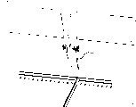
Fig. 1 is the exploded perspective view of rack of the present invention;
Fig. 2 is installed to the angle brace of back plate and the stereogram of biside plate;
Fig. 3 is the stereogram of the specific embodiments of angle brace own;
Fig. 3 A, 3B, 3C are the sectional view that is positioned at the angle brace of three kinds of diverse locations among the preceding figure;
Fig. 4 installs later rack partial section for cover plate;
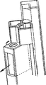
Stereogram when Fig. 5 is installed to the header board support column for header board;
Stereogram when Fig. 6 is installed to cover plate for the header board supporting;
Stereogram when Fig. 7 is installed to cabinet door bearing framework for the cabinet door;
Fig. 7 A is the rack stereogram that is equipped with header board support column and cabinet door frame;
To be rack obtaining the partial perspective view of all sealings of tightness with its top and bottom to Fig. 8;
Fig. 9 is the stereogram that two racks according to the present invention connect;
Fig. 9 A is for connecting the stereogram of two racks with two angle braces;
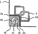
Figure 10 and 10A are with the fixing specific embodiments sectional view when released position and the fixed position respectively of cover plate of deformable seal;
Figure 11 and 11A are for realizing the sectional view of above-mentioned this fixing another embodiment with hold-down screw;
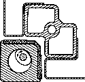
Figure 12 and 12A are for realizing the sectional view of above-mentioned this fixing another embodiment with a cam;
Figure 13,13A and 13B are for realizing sectional view and the stereogram of this fixing another embodiment with the lever with cam;
Figure 14,14A are for adopting another embodiment of the system with a helical member;
Figure 15,15A and 15B are for adopting another embodiment of the system with an eccentric part;
Figure 16,16A and 16B are for adopting another embodiment of the system with a wedge shape part;
Figure 17,17A and 17B are for adopting another embodiment of the system with a conical screw;
Figure 18 is equipped with the angle brace stereogram of two connection slots for the present invention; And
Figure 19 is the stereogram of another embodiment of angle brace.
Embodiment
In Fig. 1, can see rack A, it is by back plate 1; Four blocks of side plates 4,5,6,7; Four angle braces 8; Two header board support column C and cabinet door P form.Described back plate 1 is equipped with and contains a plurality of function columns 2 that numerous installing holes 3 that electrical switchgear uses are installed.Some described side plate is equipped with one or more protection backing plates (not shown).Described cabinet door is installed on the door bearing framework D.
According to the embodiment shown in Fig. 2,3,4, this fixture 9 is by the long elements that comprises two identical portions that are positioned at each side of bellmouth X and form.The described two identical portions cross section that is square at its top.Each part of described identical portions comprises face e or face f and two sides a, c or two sides b, d.Face e or face f design is used for holding a retaining 10c (see figure 4) described a, c of fastening as one with described moving member 10 or b, the d face is vertical mutually, it is side three bendings of described side plate and forming when forming a carriage that design is used for admitting respectively orthogonal 13b, face 13c or face 14b, the face 14c that belongs to side plate 4, these faces.Cross section is square on described moving member 10 is directly perceived, it comprises an above-mentioned retaining 10c and is rendered as two orthogonal bearing-surface 10a, 10b on intuitively, design is used for after fixed installation is finished, and supports face 13a, the face 14a of two sides 4,5 that belong to be connected respectively respectively.These two face 10a, 10b are equipped with sealing i, j respectively.It is pointed out that an above-mentioned retaining 10c also can be positioned on the fixture 9.
To describe several moving members 10 below and be installed to embodiment on the fixture 9.
With reference to Fig. 5,6,7, can see that header board supporting C can hold several header boards 17.With reference to Fig. 8, can see that the tightness at rack bottom and top seals 18 and one or more frame seal 19 and obtaining by means of one or more plates respectively.Each plate sealing 18 is firmly adhered on the plate of back, and in place between the bending edges 20 of side plate of this piece plate and side plate 4,5,6,7, and each frame seal 19 is adhered on the scaffold D of cabinet door P securely, and in place between one of the scaffold D of cabinet door and side plate 4,5,6,7.
Sealing 18,19 can make between back plate and each side plate on the one hand and obtain tightness, makes on the other hand between cabinet door frame and each side plate and obtains tightness.And the tightness between each side plate obtains by means of a plurality of angle braces.
In Fig. 7 A, can see a rack, header board supporting C is fixed to a plurality of angle braces, and the scaffold D of cabinet door is fixed to the top of angle brace, on the fixture that the scaffold and the moving member of stationary cabinet door is fixed to angle brace with identical screw.
The different phase that moving member is installed to rack general assembly among the different embodiment on the fixture below will be described.
Phase I, 4 fixtures 9 of 4 angle braces 8 are installed to (see figure 1) on 4 angles of back plate.Then, by means of will be three sides 13,14 (Fig. 2) that are bent into the side plate 4,5,6,7 of carriage be attached to inner surface a, b, c, the d of fixture 9 and side plate 4,5,6,7 be installed on the fixture of angle brace, fixture is to the side plate guiding and holding them in (Fig. 4) on the due position during its general assembly.Then, side plate (wall) extruding is positioned at the sealing 18 (Fig. 8) on plate 1 edge, back.It is pointed out that moving member can be contained on the fixture in advance, finishes the installation of moving member on the angle brace fixture then.
Second stage (Fig. 6 and Fig. 7), it is that cabinet door bearing framework D (or then be header board supporting C with cabinet door bearing framework D) is installed on the assembly then that header board is supported C, cabinet door frame sealing 19 is extruded on the top and angle brace 8 of side plate 4,5,6,7.Then cabinet door P is installed on the hinge 38 that is fixed in framework (Fig. 7).
So obtained to bear the rack that powerful mechanical stress presents the height tightness again.
According to first embodiment shown in Fig. 3,3A, 3B, the 3C and 4, the controls that moving member 10 is moved comprises that one handles nut 50, and it is installed in to be slidingly connected fixedly in the angle brace 9, and is positioned in the described angle brace by two extrusion springs 51,52.This manipulation nut 50 has an inclined-plane 53, and its axle on being fixed on moving member 10 54 is worked, thereby, move by screw 55 drive nuts 50, make moving member 10 according to moving with the perpendicular axis direction of the mobile axis of handling nut 50.Thereby make sealing press lateral edge and side plate.
In Fig. 3 A, screw 55 is tightened, and makes moving member that sealing is pressed in the edge of lateral edge and side plate, thereby obtains the corresponding tightness of assembly.
In Fig. 3 B, screw 55 unclamps, and makes moving member 10 from fixing angle brace 9 separately, so can freely handle all sides and side plate.
In Fig. 3 C, screw 55 is loose fully, handles the active force extrusion spring 52 of nut, then moving member 10 is discharged from angle brace fixture 9, thus provided moving member 10 possibility of mounting or dismounting fast.
According to the certain embodiments of the present invention shown in Figure 11 and the 11A, this fixing can the realization by means of a kind of like this controls: this controls comprises a screw 21, it is by the hole 22 that provides in the moving member 10 and be screwed in the screw of arranging in the fixture 9 23, and described two holes are positioned on the mutual extended line.According to this embodiment, from side direction operation screw, but can find out, also can be from forward and backward near this screw.Sealing 24 parts cover two acting surfaces of moving member 10, make rack increase in the tightness of the lock room of each panel, and also the situation of other embodiment as will be described below is the same.
So, in such an embodiment, screw 21 tighten generation to sealing 24 extruding on side plate 4,5,6,7 edges.Should be noted that, the existence of retaining 26, it is fixing with moving member 10, designs the excessive compression that is used for preventing to described all sealings 24.Should be noted also that this embodiment can not have these sealings and retaining head, but can not reach identical tight degree.
According to Figure 10 and the described embodiment of 10A, described fixture 9 is formed by the profile of vertical dimple (or groove) 27 of L-shaped cross section, design is used for holding the rigid member 28 that is embedded in the expandable seal 29, and sealing 29 constitutes the part of the moving member 10 of angle brace 8.The expansion of sealing 29 produces the extruding to side plate 4,5,6,7.
According to the embodiment shown in Figure 12 and the 12A, the controls that moving member 10 is moved comprises that one is rotatably installed in the cam on one 31, and is positioned at the dimple 32 of moving member 10.This 31 is fixed on the arm of fixture 9.This cam 30 is worked with the inner surface of moving member, thereby actuates 31 rotations of device (not shown) driving cam moving member 10 is slided by means of suitable, and will seal 24 and be squeezed on side plate 4,5,6,7 edges, thereby carries out installing and fixing of all panels.
According to another embodiment shown in Figure 13,13A and the 13B, a cam 32a is installed in the end of lever 33, and this lever 33 is installed on the axle 34 with hinged form, and this is 34 fixing with the arm 41 that belongs to moving member 10.In such an embodiment, cam 32 is worked with the outer surface 36 of fixture 9, and actuating of lever 33 makes fixture 9 and moving member 10 move in opposite directions mutually.In off-position, lever 33 is contained between hold-down screw 37 and the angle brace 8, and this hold-down screw 37 is screwed in the fixture 9 by the hole of lever 33, thereby tightening of screw makes assembly be locked on the fixed position.
Can expect the embodiment that another is not shown, the function nut that it for example provides, this nut comprises a helicla flute, is slidingly mounted on the inside of fixture.This nut can move by means of screw with being fixed on a co-operating on the moving member.
Also can find out other fixed mode, for example, the fixed mode shown in Figure 16, Figure 16 A, Figure 16 B, make the wedge shape part of a suitable shape, design is used for being meshed with the dimple 40 that provides in the arm 41, and described arm 41 is fixing with moving member 10, slides through the hole in the fixture 9 and installs.Equally, the available cone screw 42 of this wedge shape part replaces, and this screw 42 is screwed in the bellmouth 43 of arm 41 (Figure 17, Figure 17 A, Figure 17 B).
Another solution can be made up of the system (Figure 15, Figure 15 A, Figure 15 B) that use is installed in the system with helical member 46 (Figure 14, Figure 14 A) of arm 41 inside or has an eccentric part.
In Figure 18, can see that angle brace can comprise two grooves 15,16, design is used for by means of a plurality of Connection Elements two guessets (moving member and fixture) being connected, as shown in Figure 9.
According to another embodiment shown in Figure 19, this fixture 9 is formed by the type spare of cross section shape such as carriage, comprises two vertical branches 11,12.This type spare comprises two orthogonal inner surface a ', b ', and design is used for holding orthogonal surperficial c ', the d ' of the type spare that belongs to another side's cross section, and this another type spare constitutes the moving member of angle brace.The branches 11,12 of fixture 9 is included in inner surface a ', the b ' of the plane extension perpendicular with being positioned at the side plate of respective branch part 11,12 homonymies, so that hold the lateral edges that described side plate 4,5 is bent into carriage 13,14.Can also see that these two branches, 11,12 each parts comprise that cross section is the groove 15,16 of T shape, design is used for holding a clamping element, and the effect of clamping element is to make two racks that are set up in parallel be linked together (see figure 9).
These angle braces 8 have two functions, that is: first function that these panels are led and these panels 4,5,6,7 are fixed to second function on all angle braces 8, it is to realize by means of the edge clamping that each side plate is bent into carriage 13,14 is tightened between a ', b ' two sides and moving member 10c ', the d ' two sides of fixture 9, has finished moving member this moment and has been installed to work on the fixture.
It is pointed out that the front can be made up of one or more header board supporting members, one or more cabinet door bearing framework and one or more cabinet door.Described cabinet door bearing frame fixation is to a plurality of angle braces, and which comprises at least a hinge, described framework comprises a sealing 19, it is positioned at its bottom periphery, design is used for one side between framework D and wallboard 4,5,6,7, obtains tightness on the other hand between framework D and angle brace 8.
In all these embodiment, two functions of all angle brace performances, that is: the location of all overlays and guiding and acquisition tightness.
Angle brace can obtain two states, that is: " quiet " attitude makes all plates be mounted or dispose; And initiatively attitude make carry out all parts that plate embeds obtain tightness and (or) tightness.The moving member of supporting tightness system is so that the fashion of extrusion work that friction is eliminated.
Because the present invention has obtained to dispose the total degree of freedom of all plates, and eliminated the risk of the bad seals that rubs and cause.
Moving member can be dismantled from fixture easily, so that for example replace under situation about damaging.
Because angle brace is made up of two parts, so two parts of angle brace can be with different materials, and the aesthetic of exterior part can be improved by few cost.
It is pointed out that in these all embodiment fixture and moving member all do not have definite position, but they can independently be positioned at the inside or the outside of rack.
The present invention can make the rack completely knocked down, presents higher protection index IP or IK, and no matter it uses separately or uses with other rack connection, does not all need the user of product to dispose sealing.
In order two racks to be connect (Fig. 9) or with a rack and a pipe link, panel 1 is fixed by means of clamping element 44,45.Different elements is by with single rack identical method being installed and installing.Owing to the tightness that connects between two volumes produce is guaranteed with the contacting of plate face seal 18 of bottom by means of the frame seal 19 at top.The connection of rack room can obtain like this: both can (Fig. 9 a), it had been tightened to the associating angle brace of monolithic mutually by two simple angle braces by means of the duplex angle brace; Also can be by means of simple all angle braces (Fig. 9) by meshing with all grooves that provide in setting part 44 and all angle braces 8 that are connected that bolt-lock pin 45 is combined into one.
The connection of all racks is tight seal naturally, the tight part that does not also promptly need to add (except that connecting the setting part), and this can reduce and connects the required time of product, and can reduce the risk that causes tightness aspect defective owing to incorrect disposal.
The new ideas of the tight rack that this can be opened and connect provide the possibility of the height, width and the degree of depth that strengthen all rack connections, can strengthen product significantly at there, have large-scale distribution space, and approaching easily.Under the situation that earthquake equipment is installed, it allows people to be easy near one or more parts to be removed.
Seal this two sealings by means of frame seal and back plate, and can obtain sealed volume by means of all angle braces.The top that frame seal also forms between the part that is installed in all cabinet doors on the rack tightly connects.Under the situation that connects all products (rack), these frameworks and panel sealing also form tight the connection between different rack enclosures.Rack enclosure has been strengthened in the existence of cabinet door bearing framework.
Claims (27)
1. angle brace that is used for holding the rack of electrical switchgear, described rack has a framework, and this framework comprises:
The back plate of one supporting switching device supporting member;
A plurality of angle braces extend perpendicular to described back plate, and design is as the supporting of Side plate of machine cabinet, and the length of each angle brace is corresponding to the degree of depth of rack,
It is characterized in that, at least one angle brace (8) comprises a fixture (9) fixing with respect to described back plate (1), described fixture (9) forms a thin and long units, comprise two identical parts with square-section, described fixture (9) comprises that two faces (a, b) design is used for holding respectively and guides two side plates (4,5), and two side plates are designed to link together in twos; On the other hand, this angle brace (8) comprises a moving member (10), have one and be roughly square cross section, design is used for being installed on the above-mentioned fixing piece (9), when described moving member (10) is installed on the fixture, securely with described side plate (4,5) be fixed on described angle brace (8) and when being positioned between two other angle braces of side plate (4,5) opposite side, described moving member (10) is belonging to two side plates (4 respectively, 5) (13a 14a) goes up the generation squeezing action on two planes.
2. angle brace according to claim 1 is characterized in that, two faces (a, b) of described fixture (9) that hold described side plate (4,5) are mutually vertical.
3. angle brace according to claim 2, it is characterized in that, described moving member (10) cross section that is square, it comprises two orthogonal (10a, 10b), design is used for supporting two orthogonal (13a, 14a) of the biside plate (4,5) that belongs to be connected respectively.
4. angle brace according to claim 3 is characterized in that, (10a 10b) comprises a sealing (i, j) to two bearing-surfaces of described moving member (10).
5. angle brace according to claim 1, it is characterized in that, for each side plate (4,5), the fixture (9) of described angle brace (8) comprises, is respectively applied for two vertical planes (13b, 13c and 14b, 14c) that receive and guide two vertical planes (a, c and b, d) of biside plate (4,5).
6. according to each described angle brace of claim 1 to 5, it is characterized in that, the fixture (9) of described angle brace (8) comprises that one is installed in moving member (10) inside, the arm of Hua Donging (41) between the two positions, in primary importance, fixture separates with moving member, covers side plate (4,5,6,7) so that dispose; In the second place, these two parts move together corresponding to the fixed position that covers side plate, mobile from the primary importance to the second place realizes that by means of controls (30,33,39,40) controls is worked with the fixed part of the moving member that is in the second place.
7. angle brace according to claim 6, it is characterized in that, described controls comprises a cam (30) around axle (31) rotation installation, this axle (31) is inner fixing with fixture (9) at the dimple (32) that moving member (1) provides, rotate by means of the suitable device driving cam (30) of actuating, cause moving member (10) to slide and fixing all side plates (4,5,6,7).
8. angle brace according to claim 6, it is characterized in that, described controls comprises a cam (32a) that forms in the end of lever (33), described lever (33) rotation is installed on the axle of fixing with the arm (41) of above-mentioned moving member (10) or fixture (9) (34), described cam (32a) is worked with the outer surface of fixture (9) or moving member (10), and lever (33) remains on the fixed position of side plate by means of screw (37), described screw (37) by lever (33) a hole and be screwed in the fixture (9).
9. angle brace according to claim 6 is characterized in that, a dimple (40) that provides in above-mentioned arm (41) is provided described controls, and said dimple (40) is worked with a wedge shape part (39).
10. angle brace according to claim 6 is characterized in that, a conical dimple (43) that provides in described arm (41) is provided described controls, and works with cone screw (42).
11. angle brace according to claim 6 is characterized in that, described controls comprises that one is equipped with the system of eccentric part (45) in described arm (41).
12. angle brace according to claim 6 is characterized in that, described controls comprises that one is equipped with the system of helical member (46) in described arm (41).
13. angle brace according to claim 6, it is characterized in that, described manipulation and fixture comprise a screw (21) and are arranged in moving member (10) and two holes of fixture (9) (22,23), a hole is positioned on the extended line in another hole, a hole (22) is a through hole, and another hole (23) are screw.
14. according to each described angle brace of claim 1 to 5, it is characterized in that, the moving member (10) of described angle brace (8) comprises that one is installed in fixture (9) inside, the arm of Hua Donging (41) between the two positions, in primary importance, fixture separates with moving member, covers side plate (4,5,6,7) so that dispose; In the second place, these two parts move together corresponding to the fixed position that covers side plate, mobile from the primary importance to the second place realizes that by means of controls (30,33,39,40) controls is worked with the fixed part of the moving member that is in the second place.
15. angle brace according to claim 14, it is characterized in that, described controls comprises a cam (30) around axle (31) rotation installation, this axle (31) is inner fixing with moving member (10) at the dimple (32) that fixture (9) provides, rotate by means of the suitable device driving cam (30) of actuating, cause moving member (10) to slide and fixing all side plates (4,5,6,7).
16. according to the arbitrary described angle brace of claim 1 to 5, it is characterized in that, moving by means of a manipulation nut (50) of moving member (10) obtains, described nut (50) is installed in the fixture (9) of described angle brace in the mode that is slidingly connected, and by means of at least one extrusion spring (51,52) be positioned in the described fixture, described nut (50) comprises an inclined-plane (53), it is worked with the fixing axle (54) of moving member (10) with one, move thereby drive this manipulation nut, described moving member (10) is produced along the axis direction vertical with handling the nut mobile axis move by means of screw (55).
17. angle brace according to claim 1 is characterized in that, by forward and backward or lateral approach fixture.
18. according to the arbitrary described angle brace of claim 1 to 5, it is characterized in that, described fixture (9) comprises a profile, it comprises the groove of a L shaped cross section (27), design is used for holding a stiffener (28) that is embedded in the expandable seal (29), and sealing (29) constitutes the part of described moving member (10).
19. angle brace according to claim 1 is characterized in that, described moving member (10), or described fixture (9) comprise a retaining head (26,10c), and design is used for moving of during the assembly work described moving member of restriction (10).
20. one has the rack of the electrical switchgear of framework, this framework comprises a back plate and an a plurality of angle brace, it is characterized in that rack comprises one at least according to the arbitrary described angle brace of claim 1 to 17.
21. rack according to claim 20 is characterized in that, it comprises 4 according to the arbitrary described angle brace of claim 1 to 17 (8).
22. according to claim 20 or 21 described racks, it is characterized in that, be bent into a carriage with the lateral edges (13,14) three of the symphyogenetic described side plate of the arbitrary described angle brace of claim 1 to 17 (8) (4,5).
23., it is characterized in that it also comprises a framework (C) according to claim 20 or 21 described racks, one or more header boards (17) can be fixed on above it, and designs fix is to the front of described angle brace (8).
24. according to claim 20 or 21 described racks, it is characterized in that, it comprises that also one is fixed on the cabinet door support frame (D) on the angle brace (8), this framework (D) comprises a hinge (38) at least, described framework comprises that one is positioned at the sealing of its bottom periphery, design is used for one side between framework (D) and side plate (4,5,6,7), obtains tightness on the other hand between framework (D) and angle brace (8).
25. angle brace according to claim 1 is characterized in that, it comprises at least one groove, and design is used for by means of a bolt-lock pin angle brace of this rack being connected with the angle brace of another rack.
26. an associating angle brace is characterized in that it is formed according to the arbitrary described angle brace of claim 1 to 17 by two, and is fastening and form a monolithic and unite angle brace.
27. an angle brace that is used for holding the rack of electrical switchgear, described rack has a framework, and this framework comprises: the back plate of all supporting members of a supporting switching device; A plurality of angle braces, extend perpendicular to described back plate, design is as the supporting of all overlays of rack, the length of each angle brace is corresponding to the degree of depth of rack, it is characterized in that, at least one angle brace (8) comprises the fixture (9) fixing with respect to described back plate (1) on the one hand, this fixture is formed by the type spare of Bracket Type cross section, comprise two vertical branches (11,12), described fixture has that two faces (a ', b ') design is used for holding the lateral edges (13,14) that belongs to two side plates (4,5) respectively and to its guiding; Comprise a moving member (10) on the other hand, design is used for being installed on the described fixture (9), this moving member is formed by the type spare of square-section, comprise two faces (c ', d '), respectively with two faces of described fixture (9) (a ', b ') synergy, thereby, moving member (10) fixing on fixture (9), the above-mentioned lateral edges (13,14) of the side plate (4,5) between fixture (9) and the moving member (10) produced clamp, so that obtain side plate fixing to the tight seal of described angle brace (8).
Applications Claiming Priority (2)
| Application Number | Priority Date | Filing Date | Title |
|---|---|---|---|
| FR9801567A FR2774519B1 (en) | 1998-02-05 | 1998-02-05 | CORNER PILLAR FOR CABINET FOR HOUSING ELECTRICAL EQUIPMENT AND CABINET PROVIDED WITH SUCH A PILLAR |
| FR9801567 | 1998-02-05 |
Publications (2)
| Publication Number | Publication Date |
|---|---|
| CN1225551A CN1225551A (en) | 1999-08-11 |
| CN1155306C true CN1155306C (en) | 2004-06-23 |
Family
ID=9522807
Family Applications (1)
| Application Number | Title | Priority Date | Filing Date |
|---|---|---|---|
| CNB991018427A Expired - Lifetime CN1155306C (en) | 1998-02-05 | 1999-02-02 | Corner strut for cabinet designed to house electrical switchgear and cabinet equipped with such strut |
Country Status (6)
| Country | Link |
|---|---|
| EP (2) | EP0935324B1 (en) |
| CN (1) | CN1155306C (en) |
| DE (2) | DE69936554T2 (en) |
| ES (2) | ES2288005T3 (en) |
| FR (1) | FR2774519B1 (en) |
| PL (1) | PL190219B1 (en) |
Families Citing this family (13)
| Publication number | Priority date | Publication date | Assignee | Title |
|---|---|---|---|---|
| CN100352118C (en) * | 2002-05-23 | 2007-11-28 | 通道系统集团公司 | Equipment enclosure and method for assembling the same |
| FR2841055B1 (en) * | 2002-06-14 | 2004-12-10 | Schneider Electric Ind Sa | ELECTRICAL BOX |
| DE202007000556U1 (en) * | 2007-01-09 | 2007-10-18 | CCS Technology, Inc., Wilmington | Optical fiber distribution device |
| FR2914118B1 (en) * | 2007-03-22 | 2009-04-17 | Schneider Electric Ind Sas | ANGLE PILLAR FOR ELECTRIC BOX AND BOX THUS EQUIPPED |
| DE102007034513A1 (en) * | 2007-07-24 | 2009-01-29 | Abb Ag | Electrical control cabinet |
| FR2929457A1 (en) * | 2008-04-01 | 2009-10-02 | Schneider Electric Ind Sas | ASSEMBLY OF AN ELECTRICAL BOX |
| US8282174B2 (en) | 2009-04-17 | 2012-10-09 | General Electric Company | Corner structure for electrical enclosure |
| DE102010016489B4 (en) * | 2010-04-16 | 2013-04-25 | Rittal Gmbh & Co. Kg | Housing part for a control cabinet |
| FR2987218B1 (en) * | 2012-02-21 | 2014-02-14 | Schneider Electric Ind Sas | OSSATURE OF A BOX OR AN ELECTRICAL CABINET |
| CN103188907B (en) * | 2012-12-19 | 2016-05-18 | 上海空间电源研究所 | A kind of light-duty unit structure of high strength three-dimensional for space |
| CN104617500B (en) * | 2015-02-10 | 2017-02-01 | 北京普瑞斯玛电气技术有限公司 | Power distribution box |
| CN106711813B (en) * | 2017-02-13 | 2018-11-06 | 千盛电气集团有限公司 | A kind of low-voltage complete switch equipment of high stability |
| CN111799664B (en) * | 2020-07-20 | 2022-04-08 | 无锡市聚利机械有限公司 | Power distribution cabinet with moisture-proof function |
Family Cites Families (5)
| Publication number | Priority date | Publication date | Assignee | Title |
|---|---|---|---|---|
| FR1213831A (en) * | 1958-10-29 | 1960-04-04 | Telemecanique Electrique | Plate clamping device with interposed waterproof seal |
| DE1515507A1 (en) * | 1965-10-01 | 1969-08-28 | Bbc Brown Boveri & Cie | Door lock for switchgear |
| DE4106959C1 (en) * | 1990-03-15 | 1991-09-12 | Rittal-Werk Rudolf Loh Gmbh & Co Kg, 6348 Herborn, De | Transducer element fixture for switch cabinet frame - comprises blocks with receptors for shanks of suspension stirrups |
| DE9102900U1 (en) * | 1991-03-11 | 1992-04-09 | Siemens Ag, 8000 Muenchen, De | |
| DE9110250U1 (en) * | 1991-08-20 | 1991-10-17 | Quante Ag, 5600 Wuppertal, De |
-
1998
- 1998-02-05 FR FR9801567A patent/FR2774519B1/en not_active Expired - Fee Related
-
1999
- 1999-01-18 ES ES99410003T patent/ES2288005T3/en not_active Expired - Lifetime
- 1999-01-18 DE DE69936554T patent/DE69936554T2/en not_active Expired - Lifetime
- 1999-01-18 EP EP99410003A patent/EP0935324B1/en not_active Expired - Lifetime
- 1999-01-18 DE DE69939349T patent/DE69939349D1/en not_active Expired - Lifetime
- 1999-01-18 ES ES06022688T patent/ES2309887T3/en not_active Expired - Lifetime
- 1999-01-18 EP EP06022688A patent/EP1748525B1/en not_active Expired - Lifetime
- 1999-01-29 PL PL99331121A patent/PL190219B1/en unknown
- 1999-02-02 CN CNB991018427A patent/CN1155306C/en not_active Expired - Lifetime
Also Published As
| Publication number | Publication date |
|---|---|
| EP0935324A1 (en) | 1999-08-11 |
| PL190219B1 (en) | 2005-11-30 |
| EP0935324B1 (en) | 2007-07-18 |
| DE69936554D1 (en) | 2007-08-30 |
| DE69939349D1 (en) | 2008-09-25 |
| PL331121A1 (en) | 1999-08-16 |
| EP1748525B1 (en) | 2008-08-13 |
| FR2774519B1 (en) | 2000-03-17 |
| FR2774519A1 (en) | 1999-08-06 |
| CN1225551A (en) | 1999-08-11 |
| EP1748525A1 (en) | 2007-01-31 |
| ES2309887T3 (en) | 2008-12-16 |
| ES2288005T3 (en) | 2007-12-16 |
| DE69936554T2 (en) | 2008-03-20 |
Similar Documents
| Publication | Publication Date | Title |
|---|---|---|
| CN1155306C (en) | Corner strut for cabinet designed to house electrical switchgear and cabinet equipped with such strut | |
| CN1274188C (en) | Assembly cabinet | |
| CN1876993A (en) | Connection structure for partition walls | |
| CN111980235A (en) | Prefabricated three-dimensional wallboard for assembled interior decoration | |
| CN201122216Y (en) | LCD device and computer | |
| US7430123B2 (en) | Rack for computer system modules | |
| US11674310B2 (en) | Relocatable internal wall panel, kit and system | |
| CN212203724U (en) | Supporting seat | |
| CN212836441U (en) | Dry hanging type wallboard connecting piece | |
| CN201509377U (en) | Assembled cabinet module and assembled cabinet | |
| CN216912715U (en) | Sheet metal assembly welding tool | |
| CN2809297Y (en) | Fan fixing device | |
| CN215442578U (en) | Aluminium system curtain wall construction convenient to installation | |
| CN209981771U (en) | Shell of electrical switch cabinet | |
| CN209244044U (en) | A kind of easy-to-mount curtain wall | |
| CN220173148U (en) | Foldable photovoltaic panel support frame | |
| CN113771241B (en) | Cutter set for processing anti-cracking groove of autoclaved aerated concrete slab | |
| CN212405602U (en) | Prefabricated three-dimensional wallboard for assembled interior decoration | |
| CN220254916U (en) | High-stability aluminum alloy rack | |
| CN218998599U (en) | Server device | |
| CN218729703U (en) | LED display screen of vanning body lock | |
| CN215647762U (en) | Server cabinet | |
| CN218374530U (en) | Novel assembled type built-in energy-saving wallboard | |
| CN116614971B (en) | Combined tool-free mounting bracket for adjustable data cabinet | |
| CN211277516U (en) | Fixing clamp for manual valve shell |
Legal Events
| Date | Code | Title | Description |
|---|---|---|---|
| C06 | Publication | ||
| PB01 | Publication | ||
| C53 | Correction of patent for invention or patent application | ||
| CB02 | Change of applicant information |
Applicant after: Schneider Electric SA Applicant before: Schenider Electric SA |
|
| COR | Change of bibliographic data |
Free format text: CORRECT: APPLICANT; FROM: SCHNEIDER ELECTRIC SA TO: SCHNEIDER ELECTRIC INDUSTRIES SAS |
|
| C10 | Entry into substantive examination | ||
| SE01 | Entry into force of request for substantive examination | ||
| C14 | Grant of patent or utility model | ||
| GR01 | Patent grant | ||
| CX01 | Expiry of patent term |
Granted publication date: 20040623 |
|
| CX01 | Expiry of patent term |