CN115504681A - Glass article having a defined stress distribution and method for producing the same - Google Patents
Glass article having a defined stress distribution and method for producing the same Download PDFInfo
- Publication number
- CN115504681A CN115504681A CN202211264107.8A CN202211264107A CN115504681A CN 115504681 A CN115504681 A CN 115504681A CN 202211264107 A CN202211264107 A CN 202211264107A CN 115504681 A CN115504681 A CN 115504681A
- Authority
- CN
- China
- Prior art keywords
- layer
- region
- cladding layer
- core
- glass article
- Prior art date
- Legal status (The legal status is an assumption and is not a legal conclusion. Google has not performed a legal analysis and makes no representation as to the accuracy of the status listed.)
- Pending
Links
- 239000011521 glass Substances 0.000 title claims abstract description 299
- 238000009826 distribution Methods 0.000 title claims description 33
- 238000004519 manufacturing process Methods 0.000 title description 3
- 239000010410 layer Substances 0.000 claims abstract description 254
- 238000005253 cladding Methods 0.000 claims abstract description 206
- 239000000203 mixture Substances 0.000 claims abstract description 95
- 239000012792 core layer Substances 0.000 claims abstract description 92
- 239000005340 laminated glass Substances 0.000 claims abstract description 37
- 230000001965 increasing effect Effects 0.000 claims abstract description 23
- 230000006835 compression Effects 0.000 claims abstract description 12
- 238000007906 compression Methods 0.000 claims abstract description 12
- 238000005342 ion exchange Methods 0.000 claims description 26
- 238000000034 method Methods 0.000 claims description 19
- 238000005728 strengthening Methods 0.000 claims description 10
- 230000007704 transition Effects 0.000 claims description 7
- 229910018072 Al 2 O 3 Inorganic materials 0.000 claims description 4
- 229910004298 SiO 2 Inorganic materials 0.000 claims description 4
- 229910052744 lithium Inorganic materials 0.000 claims description 4
- 229910052700 potassium Inorganic materials 0.000 claims description 4
- 229910052725 zinc Inorganic materials 0.000 claims description 4
- 238000001816 cooling Methods 0.000 claims description 3
- 230000009467 reduction Effects 0.000 claims description 3
- 239000011248 coating agent Substances 0.000 claims description 2
- 238000000576 coating method Methods 0.000 claims description 2
- 230000001939 inductive effect Effects 0.000 claims description 2
- 239000011247 coating layer Substances 0.000 claims 1
- 230000007423 decrease Effects 0.000 abstract description 7
- 230000000717 retained effect Effects 0.000 description 24
- 150000002500 ions Chemical class 0.000 description 22
- 239000006059 cover glass Substances 0.000 description 19
- 238000003426 chemical strengthening reaction Methods 0.000 description 15
- 239000000126 substance Substances 0.000 description 9
- 239000011159 matrix material Substances 0.000 description 6
- 150000003839 salts Chemical class 0.000 description 5
- 150000001768 cations Chemical class 0.000 description 4
- 239000002609 medium Substances 0.000 description 4
- -1 alkali metal cations Chemical class 0.000 description 3
- 230000008859 change Effects 0.000 description 3
- 238000009792 diffusion process Methods 0.000 description 3
- 238000010438 heat treatment Methods 0.000 description 3
- 239000011229 interlayer Substances 0.000 description 3
- 239000000463 material Substances 0.000 description 3
- 230000007246 mechanism Effects 0.000 description 3
- 238000004088 simulation Methods 0.000 description 3
- 229910052783 alkali metal Inorganic materials 0.000 description 2
- 230000015572 biosynthetic process Effects 0.000 description 2
- 238000005336 cracking Methods 0.000 description 2
- 238000003286 fusion draw glass process Methods 0.000 description 2
- 238000007373 indentation Methods 0.000 description 2
- 230000008569 process Effects 0.000 description 2
- 238000010998 test method Methods 0.000 description 2
- 238000006124 Pilkington process Methods 0.000 description 1
- 239000000853 adhesive Substances 0.000 description 1
- 230000001070 adhesive effect Effects 0.000 description 1
- 239000005358 alkali aluminosilicate glass Substances 0.000 description 1
- 229910001413 alkali metal ion Inorganic materials 0.000 description 1
- 239000005328 architectural glass Substances 0.000 description 1
- 239000010426 asphalt Substances 0.000 description 1
- 238000007678 ball-on-ring test Methods 0.000 description 1
- 238000005452 bending Methods 0.000 description 1
- 239000005345 chemically strengthened glass Substances 0.000 description 1
- 150000001805 chlorine compounds Chemical class 0.000 description 1
- 239000002131 composite material Substances 0.000 description 1
- 238000003280 down draw process Methods 0.000 description 1
- 239000000499 gel Substances 0.000 description 1
- 239000010438 granite Substances 0.000 description 1
- 230000005484 gravity Effects 0.000 description 1
- 238000000227 grinding Methods 0.000 description 1
- 230000006872 improvement Effects 0.000 description 1
- 238000011065 in-situ storage Methods 0.000 description 1
- 239000012500 ion exchange media Substances 0.000 description 1
- 238000003475 lamination Methods 0.000 description 1
- 238000003698 laser cutting Methods 0.000 description 1
- 238000012417 linear regression Methods 0.000 description 1
- 230000014759 maintenance of location Effects 0.000 description 1
- 238000005259 measurement Methods 0.000 description 1
- 238000000691 measurement method Methods 0.000 description 1
- 238000012986 modification Methods 0.000 description 1
- 230000004048 modification Effects 0.000 description 1
- 150000002823 nitrates Chemical class 0.000 description 1
- 239000006072 paste Substances 0.000 description 1
- 229920000642 polymer Polymers 0.000 description 1
- 230000003763 resistance to breakage Effects 0.000 description 1
- 238000007679 ring-on-ring test Methods 0.000 description 1
- 239000012266 salt solution Substances 0.000 description 1
- 239000004065 semiconductor Substances 0.000 description 1
- 238000007493 shaping process Methods 0.000 description 1
- 230000035939 shock Effects 0.000 description 1
- 238000003283 slot draw process Methods 0.000 description 1
- 238000002791 soaking Methods 0.000 description 1
- 239000000243 solution Substances 0.000 description 1
- 239000006058 strengthened glass Substances 0.000 description 1
- 150000003467 sulfuric acid derivatives Chemical class 0.000 description 1
- 239000002344 surface layer Substances 0.000 description 1
- 239000010409 thin film Substances 0.000 description 1
- 235000012431 wafers Nutrition 0.000 description 1
Images


Classifications
-
- B—PERFORMING OPERATIONS; TRANSPORTING
- B32—LAYERED PRODUCTS
- B32B—LAYERED PRODUCTS, i.e. PRODUCTS BUILT-UP OF STRATA OF FLAT OR NON-FLAT, e.g. CELLULAR OR HONEYCOMB, FORM
- B32B17/00—Layered products essentially comprising sheet glass, or glass, slag, or like fibres
- B32B17/06—Layered products essentially comprising sheet glass, or glass, slag, or like fibres comprising glass as the main or only constituent of a layer, next to another layer of a specific material
-
- C—CHEMISTRY; METALLURGY
- C03—GLASS; MINERAL OR SLAG WOOL
- C03C—CHEMICAL COMPOSITION OF GLASSES, GLAZES OR VITREOUS ENAMELS; SURFACE TREATMENT OF GLASS; SURFACE TREATMENT OF FIBRES OR FILAMENTS MADE FROM GLASS, MINERALS OR SLAGS; JOINING GLASS TO GLASS OR OTHER MATERIALS
- C03C17/00—Surface treatment of glass, not in the form of fibres or filaments, by coating
- C03C17/02—Surface treatment of glass, not in the form of fibres or filaments, by coating with glass
-
- C—CHEMISTRY; METALLURGY
- C03—GLASS; MINERAL OR SLAG WOOL
- C03B—MANUFACTURE, SHAPING, OR SUPPLEMENTARY PROCESSES
- C03B17/00—Forming molten glass by flowing-out, pushing-out, extruding or drawing downwardly or laterally from forming slits or by overflowing over lips
- C03B17/02—Forming molten glass coated with coloured layers; Forming molten glass of different compositions or layers; Forming molten glass comprising reinforcements or inserts
-
- C—CHEMISTRY; METALLURGY
- C03—GLASS; MINERAL OR SLAG WOOL
- C03B—MANUFACTURE, SHAPING, OR SUPPLEMENTARY PROCESSES
- C03B17/00—Forming molten glass by flowing-out, pushing-out, extruding or drawing downwardly or laterally from forming slits or by overflowing over lips
- C03B17/06—Forming glass sheets
- C03B17/064—Forming glass sheets by the overflow downdraw fusion process; Isopipes therefor
-
- C—CHEMISTRY; METALLURGY
- C03—GLASS; MINERAL OR SLAG WOOL
- C03C—CHEMICAL COMPOSITION OF GLASSES, GLAZES OR VITREOUS ENAMELS; SURFACE TREATMENT OF GLASS; SURFACE TREATMENT OF FIBRES OR FILAMENTS MADE FROM GLASS, MINERALS OR SLAGS; JOINING GLASS TO GLASS OR OTHER MATERIALS
- C03C21/00—Treatment of glass, not in the form of fibres or filaments, by diffusing ions or metals in the surface
- C03C21/001—Treatment of glass, not in the form of fibres or filaments, by diffusing ions or metals in the surface in liquid phase, e.g. molten salts, solutions
- C03C21/002—Treatment of glass, not in the form of fibres or filaments, by diffusing ions or metals in the surface in liquid phase, e.g. molten salts, solutions to perform ion-exchange between alkali ions
-
- B—PERFORMING OPERATIONS; TRANSPORTING
- B32—LAYERED PRODUCTS
- B32B—LAYERED PRODUCTS, i.e. PRODUCTS BUILT-UP OF STRATA OF FLAT OR NON-FLAT, e.g. CELLULAR OR HONEYCOMB, FORM
- B32B2250/00—Layers arrangement
- B32B2250/03—3 layers
Abstract
A laminated glass article includes a core layer and a cladding layer directly adjacent to the core layer. The core layer is formed from a core glass composition. The clad layer is formed from a clad glass composition. The average cladding Coefficient of Thermal Expansion (CTE) is less than the average core CTE, such that the cladding layer is in compression and the core layer is in tension. The compressive stress of the cladding layer decreases with increasing distance from the outer surface of the cladding layer in an outer portion of the cladding layer, and remains substantially constant with increasing distance from the outer surface of the cladding layer in an intermediate portion of the cladding layer disposed between the outer portion and the core layer. The thickness of the intermediate portion of the cladding layer is at least about 82% of the thickness of the cladding layer.
Description
The present application is a divisional application of patent applications having application numbers 201580066395.8, application date 2015, 10, 7, entitled "glass article with defined stress distribution and method for producing same".
This application claims priority to U.S. provisional application No. 62/060,941, filed on 7/10/2014, which is incorporated herein by reference in its entirety.
Background
1. Field of the invention
The present disclosure relates generally to glass articles and, more particularly, to strengthened glass articles having a determined stress profile.
2. Background of the invention
The glass articles can be used in a wide variety of products, including, for example, cover glasses (e.g., touch screen devices such as smart phones, tablets, laptops, and monitors), automotive glazings, architectural panels, and appliances. During use, large cracks may be introduced into the surface of the glass article. For example, it has been observed that dropping as a smartphone leads to the introduction of flaws as deep as 300um in the cover glass of the smartphone. Accordingly, it would be desirable for glass articles to have high strength properties against deep flaws to improve the mechanical reliability of the glass articles.
Disclosure of Invention
Glass articles having a defined stress profile and methods of making such glass articles are disclosed.
Disclosed herein are laminated glass articles comprising a core layer and a cladding layer directly adjacent to the core layer. The core layer includes a core glass composition. The cladding layer comprises a clad glass composition. The average clad Coefficient of Thermal Expansion (CTE) of the clad glass composition is less than the average core CTE of the core glass composition, such that the clad layer is in compression and the core layer is in tension. In the outer portion of the cladding layer, the compressive stress of the cladding layer decreases with increasing distance from the outer surface of the cladding layer. The compressive stress of the cladding layer remains substantially constant with increasing distance from the outer surface of the cladding layer in an intermediate portion of the cladding layer disposed between the outer portion of the cladding layer and the core layer. The thickness of the intermediate portion of the cladding layer is at least about 82% of the thickness of the cladding layer.
Also disclosed herein is a glass article comprising a tensile zone and a compressive zone comprising an inner surface directly adjacent to the tensile zone and an outer surface opposite the inner surface. The outer portion of the compressed region extends inwardly from the outer surface of the compressed region toward the stretched region to an outer layer Depth (DOL). The middle portion of the compressed region extends inwardly from the outer DOL toward the stretched region to the middle DOL. The compressive stress distribution of the compressive region includes a first compressive stress CS 1 And a second compressive stress CS 2 . The compressive stress of the outer portion at the outer surface is CS 1 And the compressive stress at the outer DOL is CS 2 . The compressive stress of the intermediate portion is substantially constant at CS 2 。
Additional features and advantages will be set forth in the detailed description which follows, and in part will be readily apparent to those skilled in the art from that description or recognized by practicing the various embodiments described herein, including the detailed description which follows, the claims, as well as the appended drawings.
It is to be understood that both the foregoing general description and the following detailed description are exemplary and are intended to provide an overview or framework for understanding the nature and character of the claims. The accompanying drawings are included to provide a further understanding, and are incorporated in and constitute a part of this specification. The drawings illustrate one or more embodiments and, together with the description, serve to explain the principles and operations of the various embodiments.
Drawings
FIG. 1 is a partial cross-sectional view of one exemplary embodiment of a laminated structure of glass articles.
FIG. 2 is a cross-sectional view of one exemplary embodiment of a forming apparatus that may be used to form a glass article.
Fig. 3 shows a graph comparing an exemplary mechanical stress profile produced by CTE mismatch only with an exemplary chemical stress profile produced by chemical strengthening only.
Fig. 4 shows an exemplary combined stress profile formed by a combination of mechanical and chemical strengthening.
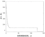
Fig. 5 shows an exemplary retained strength distribution comparison graph corresponding to a stress distribution generated only by chemical strengthening and a stress distribution generated by a combination of mechanical strengthening and chemical strengthening.
Fig. 6 shows an exemplary stress profile formed by a combination of mechanical strengthening, chemical strengthening, and ion exchange between compressive and tensile regions.
Detailed Description
Reference will now be made in detail to exemplary embodiments, which are illustrated in the accompanying drawings. Wherever possible, the same reference numbers will be used throughout the drawings to refer to the same or like parts. The components in the figures are not necessarily to scale, emphasis instead being placed upon illustrating the principles of the exemplary embodiments.
The term "average coefficient of thermal expansion" or "average CTE" as used herein refers to the average coefficient of linear thermal expansion of a given material or layer between 0 ℃ and 300 ℃. As used herein, unless otherwise indicated, the term "coefficient of thermal expansion" or "CTE" refers to the average coefficient of thermal expansion.
Chemically strengthened glass is used as cover glass for various consumer electronic devices (e.g., smart phones, tablets, personal computers, ultrabooks, televisions, and cameras). Such cover glass may be broken due to dropping of the electronic device. Without wishing to be bound by any theory, it is believed that the two major failure modes of the cover glass due to dropping of the electronic device are flexural failure and sharp contact failure. The electronic device is subjected to dynamic loading after it is dropped onto a grinding or other surface into contact therewith, causing the cover glass to bend causing flexural failure. Sharp contact failure is due to sharp indentations on the surface of the cover glass that result in sharp contact failure when the glass falls onto a rough surface (e.g., asphalt, granite, grit, etc.) that introduces breakage into the cover glass. Chemical strengthening can significantly improve the resistance of the cover glass to flexural failure by creating compressive stress on the surface of the cover glass. However, chemically strengthened cover glasses may be susceptible to dynamic sharp contact failure due to high stress concentrations caused by local indentation at the contact points and the depth of flaws that may result from such contacts (e.g., up to about 300um, as compared to a compressive layer depth of, for example, up to about 80 um). The cover glass may fail if the flaw is deep enough to penetrate through the compressive stress region. While increasing the surface compressive stress and/or increasing the depth of the compressive layer of the cover glass may increase the resistance of the cover glass to failure due to deep flaws, these techniques also increase the center tension of the cover glass. If the center tension is increased above the brittleness limit, the cover glass may exhibit brittle or extreme shatter properties.
In various embodiments, a glass article includes a tensile region and a compressive region directly adjacent to the tensile region. For example, the tensile region includes a core layer of the glass article, and the compressive region includes a cladding layer of the glass article. In some embodiments, the compressed region comprises a first compressed region and a second compressed region, and the stretched region is disposed between the first compressed region and the second compressed region. For example, the cladding layers include a first cladding layer and a second cladding layer, and the core layer is disposed between the first cladding layer and the second cladding layer. The glass article may be symmetrical, meaning that the first and second compressive regions (and the respective stress distributions) are mirror images of each other. Or, glassThe glass article may be asymmetric, meaning that the first and second compression regions are not mirror images of each other. The compression region includes an inner surface directly adjacent to the tension region and an outer surface opposite the inner surface. The outer portion of the compressed region extends inwardly from the outer surface of the compressed region toward the stretched region to an outer layer Depth (DOL). The middle portion of the compressed region extends inwardly from the outer DOL toward the stretched region to the middle DOL. The compressive stress region comprises a determined compressive stress distribution comprising a first compressive stress CS 1 And is less than CS 1 Second compressive stress CS 2 . In some embodiments, the CS 1 Including maximum compressive stress and/or CS of the compressive region 2 Including the minimum compressive stress of the compressive region. Additionally or alternatively, the compressive stress at the outer surface of the outer portion of the compression region is CS 1 And the compressive stress at the outer DOL is CS 2 And the compressive stress of the intermediate portion is substantially constant at CS 2 . For example, the compressive stress of the middle portion is at about 10%, about 5%, about 2%, or about 1% CS over the entire thickness of the middle portion 2 Within. Additionally or alternatively, a slope of the stress profile (e.g., a slope of a linear trend line of compressive stress as a function of depth within the glass article, as determined using simple linear regression) throughout a middle portion of the compressive region is substantially zero (e.g., about-7 MPa/μ ι η to about 7MPa/μ ι η, about-5 MPa/μ ι η to about 5MPa/μ ι η, about-3 MPa/μ ι η to about 3MPa/μ ι η, or about-1 MPa/μ ι η to about 1MPa/μ ι η). In some embodiments, the compressive stress region further includes an inner portion that extends inwardly from the intermediate DOL toward the tensile region to the inner DOL. The determined compressive stress distribution further comprises a stress distribution at CS 1 And CS 2 Third compressive stress CS therebetween 3 . In some embodiments, the compressive stress of the inner portion is CS at the intermediate DOL 2 Or substantially equal to CS 2 At the inner DOL is CS 3 。
Fig. 1 is a cross-sectional view of an exemplary embodiment of a glass article 100. In some embodiments, glass article 100 comprises a laminated sheet comprising multiple glass layers. The laminated sheet may be substantially flat (i.e., flat) as shown in fig. 1, or may not be flat (i.e., curved). In other embodiments, the glass article comprises a shaped glass article. For example, the laminated sheet is contacted with a shaping surface of a mold to form a shaped glass article. Glass article 100 includes core layer 102 disposed between first cladding layer 104 and second cladding layer 106. In some embodiments, first cladding layer 104 and second cladding layer 106 are outer layers, as shown in fig. 1. In other embodiments, the first cladding layer and/or the second cladding layer is an intermediate layer disposed between the core layer and the outer layer.
In some embodiments, core layer 102 comprises a core glass composition and first and/or second cladding layers 104 and 106 comprise a cladding glass composition that is different from the core glass composition. As described herein, the core glass composition and the clad glass composition are different from each other prior to chemically strengthening the glass article. For example, in the embodiment shown in fig. 1, core layer 102 comprises a core glass composition and first cladding layer 104 and second cladding layer 106 each comprise a cladding glass composition. In other embodiments, the first cladding layer comprises a first clad glass composition and the second cladding layer comprises a second clad glass composition that is different from the core glass composition and/or the first clad glass composition.
The glass article may be formed using a suitable process, such as a fusion draw process, a downdraw process, a slot draw process, an updraw process, or a float process. In some embodiments, a fusion draw process is used to form the glass article. Fig. 2 is a cross-sectional view of an exemplary embodiment of an overflow distributor 200 that can be used to form a glass article, such as glass article 100. The overflow distributor 200 may be configured as described in U.S. patent No. 4,214,886, which is incorporated herein by reference in its entirety. For example, overflow distributor 200 includes a lower overflow distributor 220 and an upper overflow distributor 240 positioned above the lower overflow distributor. Lower overflow distributor 220 includes a trough 222. Core glass composition 224 is melted and fed into trough 222 in a viscous state. Core glass composition 224 forms core layer 102 of glass article 100, as described further below. The upper overflow distributor 240 includes a groove 242. The clad glass composition 244 is melted and fed into the groove 242 in a viscous state. Clad glass composition 244 forms first and second cladding layers 104 and 106 of glass article 100, as described further below.
The coated glass composition 244 overflows through the trough 242 and flows down the opposing contoured outer surfaces 246 and 248 of the overflow distributor 240. Clad glass composition 244 is deflected outwardly by upper overflow distributor 240 such that the clad glass composition flows around lower overflow distributor 220 and contacts core glass composition 224 flowing over outer forming surfaces 226 and 228 of the lower overflow distributor. The separate streams of clad glass composition 244 are fused to separate streams of core glass composition 224 flowing down each of the outer forming surfaces 226 and 228 of underflow distributor 220, respectively. After the streams of core glass composition 224 converge at draw line 230, clad glass composition 244 forms first and second cladding layers 104 and 106 of glass article 100.
In some embodiments, core glass composition 224 of core layer 102 in a viscous state is contacted with clad glass composition 244 of first and second cladding layers 104 and 106 in a viscous state to form a laminated sheet. In some such embodiments, the laminated sheet is a portion of the glass ribbon exiting from draw line 230 of lower overflow distributor 220, as shown in fig. 2. The glass ribbon may be drawn from lower overflow distributor 220 by any suitable means including, for example, gravity and/or pulling rollers. As the glass ribbon exits lower overflow distributor 220, the glass ribbon cools. The glass ribbon is severed to separate the laminated sheets therefrom. Thus, a laminated sheet is cut from the glass ribbon. The glass ribbon may be severed using any suitable technique, such as scoring, bending, thermal shock, and/or laser cutting. In some embodiments, glass article 100 comprises a laminated sheet as shown in fig. 1. In other embodiments, the laminated sheet can be further processed (e.g., cut or molded) to form the glass article 100.
Although the glass article 100 shown in fig. 1 includes three layers, other embodiments are also included herein. In other embodiments, the glass article may have a determined number of layers, such as two, four, or more layers. For example, a glass article comprising two layers can be formed using two overflow distributors arranged such that the two layers join upon exit from each draw line of the overflow distributor, or a glass article comprising two layers can be formed using a single overflow distributor having separate grooves such that the two glass compositions flow from the opposing shaped outer surfaces of the overflow distributor and converge at the draw line of the overflow distributor. Glass articles containing four or more layers may be formed using additional overflow distributors and/or using overflow distributors with separate grooves. Thus, a glass article having a determined number of layers can be formed by changing the overflow distributor accordingly.
In some embodiments, glass article 100 comprises a thickness of at least about 0.05mm, at least about 0.1mm, at least about 0.2mm, or at least about 0.3mm. Additionally or alternatively, glass article 100 comprises a thickness of at most about 3mm, at most about 2mm, at most about 1.5mm, at most about 1mm, at most about 0.7mm, or at most about 0.5 mm. For example, the glass article comprises the following thicknesses: about 0.1 to 3mm, about 0.1 to 1mm, or about 0.3 to 0.7mm. In some embodiments, the ratio of the thickness of core layer 102 to the thickness of glass article 100 is at least about 0.5, at least about 0.7, at least about 0.8, at least about 0.85, at least about 0.9, or at least about 0.95. In some embodiments, the thickness of the second layer (e.g., each of the first cladding layer 104 and the second thickness 106) is about 0.01-0.3mm.
In some embodiments, glass article 100 is mechanically strengthened. For example, the clad glass composition of first and/or second cladding layers 104 and 106 includes a different average Coefficient of Thermal Expansion (CTE) than the core glass composition of core layer 102. In some embodiments, first and second cladding layers 104 and 106 are formed from glass compositions having an average CTE lower than that of core layer 102. The CTE mismatch (i.e., the difference between the average CTE of the first and second cladding layers 104 and 106 and the average CTE of the core layer 102) results in the formation of compressive stress in the cladding layers and tensile stress in the core layer after cooling of the glass article 100.
In some embodiments, the average CTE of core layer 102 differs from the average CTE of first and/or second cladding layers 104 and 106 by at least about 5x10 -7 ℃ -1 At least about 15x10 -7 ℃ -1 At least about 25x10 -7 ℃ -1 Or at least about 30x10 -7 ℃ -1 . Additionally or alternatively, the average CTE of core layer 102 differs by at most about 100x10 from the average CTE of first and/or second cladding layers 104 and 106 -7 ℃ -1 Up to about 75x10 -7 ℃ -1 Up to about 50x10 -7 ℃ -1 Up to about 40x10 -7 ℃ -1 Up to about 30x10 -7 ℃ -1 Up to about 20x10 -7 ℃ -1 Or up to about 10x10 -7 ℃ -1 . In some embodiments, the clad glass composition comprises up to about 66x10 -7 ℃ -1 Up to about 55x10 -7 ℃ -1 Up to about 50x10 -7 ℃ -1 Up to about 40x10 -7 ℃ -1 Or up to about 35x10 -7 ℃ -1 Average CTE of (2). Additionally or alternatively, the clad glass composition comprises at least about 10x10 -7 ℃ 1 At least about 15x10 -7 ℃ 1 At least about 25x10 -7 ℃ -1 Or at least about 30x10 -7 ℃ -1 The average CTE of (2). Additionally or alternatively, the core glass composition comprises at least about 40x10 -7 ℃ 1 At least about 50x10 -7 ℃ 1 At least about 55x10 -7 ℃ -1 At least about 65x10 -7 ℃ 1 At least about 70x10 -7 ℃ 1 At least about 80x10 -7 ℃ 1 Or at least about 90x10 -7 ℃ -1 Average CTE of (2). Additionally or alternatively, the core glass composition comprises up to about 120x10 -7 ℃ -1 Up to about 110x10 -7 ℃ -1 Up to about 100x10 -7 ℃ -1 Up to about 90x10 -7 ℃ -1 Up to about 75x10 -7 ℃ -1 Or up to about 70x10 -7 ℃ -1 Average CTE of (2).
In some embodiments, glass article 100 is chemically strengthened. For example, the glass article 100 is strengthened using an ion exchange treatment to increase the compressive stress in a region of the glass article proximate to an outer surface of the glass article (e.g., an outer portion of the compressive region, as described herein). In some embodiments, the ion exchange treatment comprises applying an ion exchange medium to one or more surfaces of the glass article 100. The ion exchange media comprises: solutions, pastes, gels, or other containing larger ions to be exchanged for smaller ions in the glass matrixA suitable medium. For example, the compressive layer of glass article 100 comprises an alkali aluminosilicate glass. Thus, the smaller ions in the glass surface layer and the larger ions in the ion exchange medium are monovalent alkali metal cations (e.g., li) + 、Na + 、K + 、Rb + And/or Cs + ). Alternatively, the monovalent cation in glass article 100 may be a monovalent cation other than an alkali metal cation (e.g., ag) + Etc.) may be substituted. In some embodiments, the ion exchange medium comprises a molten salt solution, and the ion exchange treatment comprises immersing the laminated glass article in a molten salt bath comprising smaller ions (e.g., na) to be mixed with the glass matrix + And/or Li + ) Exchanged larger ions (e.g., K) + And/or Na + ). In some embodiments, the molten salt bath includes salts of larger alkali metal ions (e.g., nitrates, sulfates, and/or chlorides). For example, the molten salt bath includes molten KNO 3 Molten NaNO 3 Or a combination thereof. Additionally or alternatively, the molten salt bath has a temperature of about 380 to about 450 ℃ and a soaking time of about 2 to about 16 hours. By replacing smaller ions in the glass matrix with larger ions at the surface of the glass article 100, the compressive stress of the compressive layer is increased near the outer surface of the glass article.
Fig. 3 shows a graph of an exemplary mechanical stress profile 302 produced by CTE mismatch alone compared to an exemplary chemical stress profile 304 produced by chemical strengthening alone. The stress distribution is represented as a graph of stress versus depth within the glass article. Depth within the glass article (given as distance relative to the outer surface of the glass article) is plotted on the x-axis, and stress is plotted on the y-axis.
Referring to mechanical stress profile 302, the compressive region (e.g., cladding layer) has a thickness of about 50um and a first compressive stress of about 150 MPa. The mechanical stress distribution 302 is a step function. Thus, the compressive stress is substantially constant as a surface compressive stress throughout the compressive region, and at the interface between the compressive region and the tensile region (e.g., at the interface between the cladding layer and the core layer), the stress transitions from the surface compressive stress to a maximum tensile stress in a stepwise manner.
Referring to chemical stress distribution 304, the compressive region extends to a DOL of about 80um and has a surface compressive stress of about 900MPa. The stress transitions continuously from a surface compressive stress at the outer surface of the compressive region to a maximum tensile stress within the tensile region. Thus, unlike the mechanical stress distribution 302, the chemical stress distribution 304 does not have a region of constant compressive stress or a step-wise change between a region of compressive stress and a region of tensile stress.
In some embodiments, glass article 100 is strengthened by a combination of mechanical and chemical strengthening. For example, a glass article 100 (e.g., a glass laminate) including a CTE mismatch as described above is chemically strengthened to further increase the compressive stress near the outer surface of the compressive layer. Fig. 4 shows an exemplary combined stress profile formed by a combination of mechanical and chemical strengthening. The stress profile of the glass article can be measured using any suitable technique, for example, using a birefringence-based measurement technique or a Refractive Near Field (RNF) technique. Exemplary standards for stress measurement include, for example, ASTM C1422 and ASTM C1279. The stress profile includes stress in the glass article 100 related to depth within the glass article. The depth within the glass article 100 (given as the distance relative to the outer surface of the glass article) is plotted on the x-axis, and the stress is plotted on the y-axis. The depth within the glass article may be referred to herein as a depth of layer (DOL). Compressive stress is shown as the positive y-axis and tensile stress is shown as the negative y-axis. However, the values of compressive stress and tensile stress described herein refer to the absolute values of the stress. Thus, the tensile stress is herein a positive value, not a negative value. It will be noted that fig. 4 only shows a portion of the stress distribution of glass article 100 through a portion of the thickness of the glass article (e.g., through one cladding layer and a portion of the core layer). For a symmetric glass article, the stress distribution through the remaining thickness portion of the glass article is a mirror image of the stress distribution portion shown in FIG. 4. In the example shown in fig. 4, the compressive region (e.g., cladding layer) has a thickness of about 125um, a first compressive stress of about 900MPa, and a second compressive stress of about 100 MPa. The compressive stress region includes an outer portion (which extends inwardly from an outer surface of the compressive region toward the tensile region to an outer DOL) and an intermediate portion (which extends inwardly from the outer DOL toward the tensile region to an intermediate DOL). In some embodiments, the outer portion of the compressive region comprises an ion-exchanged surface region in which the glass composition profile and/or stress profile is created at least in part by diffusing larger ions into the glass matrix and smaller ions out of the glass matrix within the ion-exchanged region (e.g., by subjecting the laminated glass article to an ion-exchange treatment as described herein). For example, the ion-exchanged surface region may be identified as having a stress profile having a particular shape that indicates that it was at least partially created by the ion-exchange treatment (e.g., an error function). Additionally or alternatively, the ion-exchanged surface region may be identified as a region at a surface of the glass article in which the compressive stress decreases with depth within the glass article, in comparison to a substantially constant compressive stress within a middle portion of the compressive region. In the example shown in fig. 4, the outer DOL is about 10um, and the intermediate DOL is about 125um. Thus, the thickness of the outer portion of the compressed region (denoted as outer DOL) is about 8% of the thickness of the compressed region or cladding layer, and the thickness of the middle portion of the compressed region is about 92% of the thickness of the compressed region or cladding layer. In some embodiments, the thickness of the outer portion of the compression region is at most about 18%, at most about 16%, at most about 14%, at most about 12%, at most about 10%, at most about 8%, at most about 6%, at most about 4%, or at most about 2% of the thickness of the compression region. Additionally or alternatively, the thickness of the outer portion of the compressed region is at least about.1%, at least about 0.5%, or at least about 1% of the thickness of the compressed region. In some embodiments, the thickness of the middle portion of the compressed region is at least about 82%, at least about 84%, at least about 86%, at least about 88%, at least about 90%, at least about 92%, at least about 94%, at least about 96%, or at least about 98% of the thickness of the compressed region. Additionally or alternatively, the thickness of the middle portion of the compressed region is at most about 99.9%, at most about 99.5%, or at most about 99% of the thickness of the compressed region. Limiting the thickness of the outer portions of the compressive region, or increasing the thickness of the middle portion of the compressive region, can achieve a combination of improved retained strength and lower tensile stress within the glass articles described herein (e.g., by providing a higher surface compressive stress, a thicker compressive stress region or deep total DOL, and a lower area under the compressive stress profile).
In the example shown in fig. 4, the compressive stress decreases rapidly and continuously from a first compressive stress at the outer surface of the compressive region to a second compressive stress at the outer DOL, remains substantially constant at the second compressive stress from the outer DOL to the inner DOL, and then transitions from the second compressive stress to a maximum tensile stress in a stepwise change at the interface between the compressive region and the tensile region. In the embodiment shown in fig. 4, the intermediate DOL is equal to the thickness of the cladding layer. In other embodiments, the intermediate DOL is less than the thickness of the cladding layer.
In some embodiments, glass article 100 is chemically strengthened to increase the compressive stress in the outer portions of the cladding layer without increasing the compressive stress in the middle portion of the cladding layer. Thus, the chemical strengthening is performed in such a way that the compressive layer is not chemically strengthened throughout its thickness, and as described herein, after the chemical strengthening, the compressive layer includes an intermediate portion having a substantially constant compressive stress. For example, the time and/or temperature at which chemical strengthening is performed may be limited, thereby limiting the depth of passage through the ion exchange zone.
The retained strength of the glass article may be determined based on a stress distribution of the glass article. For example, the retention strength is determined by: a flaw is formed that extends from a surface of the glass article to a specified depth, and then a strength of the glass article after the flaw is formed is determined. The strength is the flexural strength of the glass article, which is determined using, for example, the ring-on-ring test method (e.g., as described in ASTM C1499-09), the ball-on-ring test method, the three-point bend test method, the four-point bend test method, or other suitable methods or techniques. The retained strength may be determined using a fracture mechanism simulation based on the stress distribution of the glass article. Fig. 5 shows an exemplary retained strength distribution comparison graph corresponding to a stress distribution generated only by chemical strengthening and a stress distribution generated by a combination of mechanical strengthening and chemical strengthening. The retained intensity profile is expressed as a retained intensity versus flaw size. Flaw size (given as the distance the flaw extends relative to the outer surface of the glass article) is plotted on the x-axis, and retained strength is plotted on the y-axis. The chemical retained strength distribution 504 is generated using a simulation of the rupture mechanism based on the chemical stress distribution 304 as shown in fig. 3, and the combined retained strength distribution 506 is generated using a simulation of the rupture mechanism based on the combined stress distribution as shown in fig. 4.
As shown in fig. 5, the chemical retained strength profile 504 and the combined retained strength profile 506 each include a higher retained strength (e.g., at least about 200 MPa) near the outer surface of the glass article, which can help avoid breakage of the glass article due to shallower flaws (e.g., less than about 10 um). However, the combined retained strength profile 506 maintains a higher retained strength deeper into the glass article than the chemical retained strength profile 504. For example, for flaw sizes of about 70-300um, the retained strength of the combined retained strength profile 506 is higher than the chemical retained strength profile 504, which may help avoid breakage of the glass article due to deeper flaws. Flaws introduced into the cover glass due to dropping of an electronic device (e.g., a smartphone) typically have flaw sizes on the order of 70-300 um. Thus, an improvement in resistance to breakage due to such flaw size translates into improved drop performance compared to retained strength profile 504 for cover glasses comprising retained strength profiles similar to combined retained strength profile 506. Furthermore, improved resistance to cracking due to large flaws may be achieved by combining the retained strength profile 506 as compared to the retained strength profile 504 without significantly increasing the maximum tensile stress of the tensile zone. For example, maintaining a more constant level of compressive stress in a deeper compressive region (e.g., over the middle portion) may help maintain a lower area under the compressive portion of the stress profile proportional to the maximum tensile stress in the tensile region while also providing protection from cracking caused by deeper flaws. Thus, the maximum tensile stress can be maintained below the brittleness limit. Additionally or alternatively, the distance between the outer DOL and the intermediate DOL (i.e., the thickness of the intermediate portion of the compressive region) is sufficiently large to maintain a high compressive stress deep into the glass article (e.g., achieving improved resistance to fracture due to large flaws) without increasing the maximum tensile stress to an unacceptable level (e.g., above the brittleness limit).
In some embodiments, the glass article is strengthened between the compressive region and the tensile region by ion exchange to form an inner portion of the compressive region adjacent to the tensile region and having an increased compressive stress relative to an intermediate portion of the compressive region. Glass article 100 between first cladding layer 104 and core layer 102 and/or between second cladding layer 106 and core layer 102 is strengthened, for example, by ion exchange. In some embodiments, the inner portion of the compressive region comprises an ion-exchanged interface region in which the glass composition profile and/or stress profile is created at least in part by diffusing larger ions into the glass matrix and smaller ions out of the glass matrix within the ion-exchanged interface region (e.g., by ion-exchanging between the cladding layer and the core layer at the interface between the cladding layer and the core layer, as described herein). For example, an ion-exchanged interface region can be identified as having a stress profile with a particular shape that indicates that it is at least partially created by ion-exchange (e.g., an error function). Additionally or alternatively, the ion-exchanged interface region may be identified as a region at an interface between the compressive region and the tensile region in which the compressive stress increases with depth within the glass article, as compared to a substantially constant compressive stress within a middle portion of the compressive region.
In some embodiments, first cladding layer 104 and/or second cladding layer 106 comprise a lower CTE, ion-exchangeable glass composition, and core layer 102 comprises a higher CTE, ion-exchangeable glass composition. Suitable glass compositions may include those described in U.S. patent application publication No. 2014/0141217, which is incorporated herein by reference in its entirety. Examples of such glass compositions are shown in the table1, wherein IX410-8 denotes ion exchange at 410 ℃ for 8 hours, CS denotes compressive stress, and DOL denotes depth of layer. In some embodiments, the core glass includes a CTE high enough for mechanical strengthening of the glass article and a K sufficient 2 The O concentration is used for interfacial ion exchange.
Table 1: exemplary Low CTE ion exchangeable clad glass compositions

Table 1: exemplary Low CTE ion exchangeable clad glass compositions


Table 1: exemplary Low CTE ion exchangeable clad glass compositions


Exemplary glass compositions that can be used as core glass compositions and various properties of the glass compositions are shown in table 2. In some embodiments, the core glass includes cations (e.g., na) that are mobile with small radii in the clad glass + And/or Li + ) Exchanged large radius migratable cations (e.g., K) + And/or Cs + ). When heating is applied to the glass article 100 (e.g., during formation of the glass article), larger ions in the core glass occur with smaller ions in the clad glassAnd (6) exchanging. In some embodiments, heating the glass article 100 during lamination is sufficient to cause ion exchange between the cladding layer and the core layer without any additional or subsequent ion exchange heat treatment. Ion exchange between the core layer and the cladding layer increases the compressive stress extending inward from the intermediate DOL toward the tensile region to an inner portion of the compressive region of the inner DOL.
Table 2: exemplary core glass compositions


Table 2: exemplary core glass composition (continue)


Table 2: exemplary core glass composition (continuous)


Table 2: exemplary core glass composition (continue)


Table 2: exemplary core glass composition (continue)


Table 2: exemplary core glass composition (continue)


Table 2: exemplary core glass composition (continuous)


Table 2: exemplary core glass composition (continue)


In some embodiments, the clad glass comprises an ion exchangeable glass havingA sufficiently low CTE is used to mechanically strengthen the glass article. For example, in one exemplary embodiment, the clad glass comprises: about 65-70 mol% SiO 2 About 9-14 mol% Al 2 O 3 And about 0-11 mol% of B 2 O 3 As a glass network former; about 5-10 mol% of a basic oxide R 2 O, wherein R is at least one of Li, na and K; and about 3-11 mole% of a divalent oxide MO, wherein M is at least one of Mg, ca, ba, and Zn. Such glass compositions typically have an average CTE of less than or equal to 55x10 -7 /° c and is suitable for strengthening by ion exchange.
In another exemplary embodiment, a clad glass comprises: about 65-68 mol% SiO 2 About 10-13 mol% of Al 2 O 3 And about 6-9 mol% of B 2 O 3 As a glass network former; about 6-9 mol% of a basic oxide R 2 O, wherein R is at least one of Li, na, and K; and about 7-10 mole% of a divalent oxide MO, wherein M is at least one of Mg, ca, ba, and Zn. Such glass compositions typically have an average CTE less than or equal to 55x10 -7 /° c and is suitable for strengthening by ion exchange.
Fig. 6 shows an exemplary stress profile formed by a combination of mechanical strengthening, chemical strengthening, and ion exchange between compressive and tensile regions. In the example shown in fig. 6, the compressive region has a thickness of about 125um, a first compressive stress of about 600MPa, a second compressive stress of about 100MPa, and a third compressive stress of about 300MPa. The compressive stress region includes an outer portion (e.g., a surface ion exchange region that extends inward from an outer surface of the compressive region toward the tensile region to an outer DOL), an intermediate portion (which extends inward from the outer DOL toward the tensile region to an intermediate DOL), and an inner portion (e.g., an interfacial ion exchange region that extends inward from the intermediate DOL toward the tensile region to an inner DOL). In the example shown in fig. 6, the outer DOL is about 10um, the middle DOL is about 115um, and the inner DOL is about 125um. Thus, the compressive stress decreases rapidly and continuously from a first compressive stress at the outer surface of the compressive region to a second compressive stress at the outer DOL, remains substantially constant at the second compressive stress from the outer DOL to the intermediate DOL, then increases rapidly and continuously from the second compressive stress at the intermediate DOL to a third compressive stress at the inner DOL, and then transitions from the third compressive stress to a maximum tensile stress in a step change at the interface between the compressive region and the tensile region. The increased compressive stress of the inner portion of the compressive region may further increase the resistance of the glass to breakage due to deep flaws without increasing the maximum tension of the tensile region sufficiently to cause the glass article to exhibit frangible behavior.
In some embodiments, the CS 1 At least about 400MPa, at least about 500MPa, at least about 600MPa, at least about 700MPa, at least about 800MPa, or at least about 900MPa. In addition or alternatively, CS 1 At most about 1000MPa or at most about 900MPa. For example, CS 1 About 400 to 1000MPa.
In some embodiments, CS 2 At least about 50MPa, at least about 100MPa, at least about 200MPa, or at least about 300MPa. In addition or alternatively, CS 2 Up to about 450MPa, up to about 400MPa, up to about 300MPa, or up to about 200MPa. For example, CS 2 About 50 to 450MPa.
In some embodiments, CS 3 At least about 100MPa, at least about 200MPa, at least about 300MPa, or at least about 400MPa. In addition or alternatively, CS 3 At most about 800MPa, at most about 700MPa, or at most about 600MPa. For example, CS 3 About 100 to 800MPa.
In some embodiments, the outer DOL is at least about 10um, at least about 20um, at least about 30um, or at least about 40um. Additionally or alternatively, the outer DOL is at most about 50um, at most about 40um, or at most about 30um. For example, the outer DOL is about 10-50 μm.
In some embodiments, the intermediate DOL is at least about 30um, at least about 50um, at least about 70um, or at least about 90um. Additionally or alternatively, the intermediate DOL is at most about 250um, at most about 200um, at most about 170um, at most about 150um, at most about 130um, at most about 120um, at most about 100um, at most about 80um, or at most about 60um. For example, the intermediate DOL is about 30 to 250 μm.
In some cases, the inner DOL corresponds to an interface between a compressed region and a stretched region. For example, the inner DOL is equal to or substantially equal to the thickness of each clad layer of the glass article.
In some embodiments, a glass article includes a laminated glass composite including a first glass layer and a second glass layer. The first glass layer includes a first glass composition and the second glass layer includes a second glass composition different from the first glass composition. The first glass layer includes an outer surface and an inner surface. The second glass layer is in direct contact with the inner surface of the first glass layer. The first glass layer is in compression and the second glass layer is in tension. The variable compressive stress profile of the first glass layer includes a first region and a second region. In the first region, the compressive stress decreases in a direction from the outer surface inward toward the inner surface. The compressive stress remains substantially constant in the second region (e.g., within about 20%, within about 10%, within about 5%, or within about 2% of the average compressive stress of the second region).
The glass articles described herein can be used in a variety of applications including, for example, cover glass or glass backplane applications in consumer or commercial electronic devices, such as LCD and LED displays, computer monitors, and Automated Teller Machines (ATMs); touch screen or touch sensor applications; portable electronic devices including, for example, mobile phones, personal media players, and tablet computers; integrated circuit applications including, for example, semiconductor wafers; photovoltaic applications; architectural glass applications; automotive or vehicular glazing applications; or commercial or household appliance applications.
It will be apparent to those skilled in the art that various modifications and variations can be made in the present invention without departing from the scope or spirit of the invention. Accordingly, the invention is not to be restricted except in light of the attached claims and their equivalents.
The present application also relates to the following items.
1. A laminated glass article, comprising:
a core layer comprising a core glass composition; and
a cladding layer directly adjacent to the core layer and comprising a cladding glass composition having an average cladding Coefficient of Thermal Expansion (CTE) less than an average core CTE of the core glass composition, such that the cladding layer is in compression and the core layer is in tension;
wherein in the outer portion of the cladding layer, the compressive stress of the cladding layer decreases with increasing distance from the outer surface of the cladding layer; and
wherein the compressive stress of the cladding layer remains substantially constant with increasing distance from the outer surface of the cladding layer in a middle portion of the cladding layer, the middle portion of the cladding layer being disposed between an outer portion of the cladding layer and the core layer, and the middle portion of the cladding layer having a thickness of at least about 82% of the thickness of the cladding layer.
2. The laminated glass article of item 1, wherein the outer portion of the cladding layer comprises an ion exchanged surface region of the cladding layer.
3. The laminated glass article of item 1 or 2, wherein the stress profile of the clad layer in the outer portion of the clad layer comprises an error function.
4. The laminated glass article of any of items 1-3, wherein a thickness of the middle portion of the cladding layer is at most about 99.9% of a thickness of the cladding layer.
5. The glass article of any of items 1-4, wherein the cladding layer has a compressive stress at an outer surface of the cladding layer from about 400MPa to about 1000MPa.
6. The glass article of any of items 1-5, wherein the cladding layer has a compressive stress in a middle portion of the cladding layer from about 50MPa to about 450MPa.
7. The glass article of any of items 1-6, wherein the thickness of the outer portion of the cladding layer is about 10 μm to about 50 μm.
8. The glass article of any of items 1-7, wherein a thickness of the middle portion of the cladding layer is about 1 μ ι η to about 240 μ ι η.
9. The glass article of any of items 1-8, wherein the compressive stress of the cladding layer increases with increasing distance from the outer surface of the cladding layer in an inner portion of the cladding layer disposed between a middle portion of the cladding layer and the core layer.
10. The laminated glass article of item 9, wherein the inner portion of the cladding layer comprises an ion exchanged interfacial region of the cladding layer.
11. The laminated glass article of item 9 or 10, wherein the stress profile of the clad layer in the inner portion of the clad layer comprises an error function.
12. The glass article of any of items 1-11, wherein the average core CTE is at least about 10 higher than the average clad CTE -7 /℃。
13. The glass article of any of items 1-12, wherein the cladding layer comprises a first cladding layer and a second cladding layer, and the core layer is disposed between the first cladding layer and the second cladding layer.
14. A glass article, comprising:
a stretch zone; and
a compressed region comprising an inner surface directly adjacent to the stretched region and an outer surface opposite the inner surface, outer portions of the compressed region extending inwardly from the outer surface of the compressed region toward the stretched region to an outer layer Depth (DOL), a middle portion of the compressed region extending inwardly from the outer DOL toward the stretched region to a middle DOL;
wherein the compressive stress distribution of the compressive region comprises a first compressive stress CS 1 And is less than CS 1 Second compressive stress CS of 2 The compressive stress of the outer portion at the outer surface is CS 1 In aCompressive stress at the outer DOL is CS 2 And the compressive stress of the intermediate portion is substantially constant at CS 2 (ii) a And
wherein the outer DOL is at most about 18% of the thickness of the compressed region.
15. The glass article of item 14, wherein the outer portion of the compressive region comprises an ion exchanged surface region.
16. The glass article of item 14 or 15, wherein the compressive stress profile of the compressive region comprises an error function in an outer portion of the compressive region.
17. The laminated glass article of any of items 14 to 16, wherein a distance between the outer DOL and the intermediate DOL is at least about 82% of the thickness of the compressed region.
18. The glass article of any of items 14-17, wherein the compressive stress of the outer portion is from the CS at the outer surface 1 (iii) continuous reduction to CS at the outer DOL 2 。
19. The glass article of any of items 14 to 18, wherein CS 1 About 400 to 1000MPa.
20. The glass article of any of items 14 to 19, wherein CS 2 About 50 to 450MPa.
21. The glass article of any of items 14 to 20, wherein the external DOL is about 10 μ ι η to about 50 μ ι η.
22. The glass article of any of items 14-21, wherein the intermediate DOL is about 30 μ ι η to about 250 μ ι η.
23. The glass article of any of clauses 14 to 22, further comprising an inner portion of the compressive region extending inwardly from the intermediate DOL toward the tensile region to an inner DOL;
wherein the compressive stress distribution of the compressive region comprises a distribution at CS 2 And CS 1 Third compressive stress CS therebetween 3 And the compressive stress of the inner portion at the intermediate DOL is CS 2 And compressive stress at internal DOL of CS 3 。
24. The glass article of item 23, wherein the inner portion of the compressive region comprises an ion exchanged interface region.
25. The glass article of item 23 or 24, wherein the compressive stress profile of the compressive region comprises an error function in an inner portion of the compressive region.
26. The glass article of any of items 14-25, wherein the tensile region comprises a core layer comprising a core glass composition, and the compressive region comprises a cladding layer comprising a cladding glass composition different from the core glass composition.
27. The glass article of item 26, wherein a core Coefficient of Thermal Expansion (CTE) of the core glass composition is at least about 10 higher than a clad CTE of the clad glass composition -7 /℃。
28. The glass article of item 26 or 27, wherein the compressive region comprises a first compressive region and a second compressive region, and the tensile region is disposed between the first compressive region and the second compressive region.
29. A method, the method comprising:
contacting a molten core glass with a molten clad glass to form a laminated glass article comprising a core layer and a clad layer directly adjacent to the core layer, the core glass having a core Coefficient of Thermal Expansion (CTE) at least about 10 times greater than a clad CTE of the clad glass -7 /℃;
Cooling the laminated glass article, thereby creating a tensile stress in the core layer and a compressive stress in the cladding layer due to the difference in the core CTE and the cladding CTE;
chemically strengthening the laminated glass article to increase compressive stress in outer portions of the cladding layer extending inwardly from an outer surface of the cladding layer toward the core layer to an outer layer Depth (DOL) without increasing compressive stress in a middle portion of the cladding layer extending inwardly from the outer DOL toward the core layer to a middle DOL, the middle portion of the cladding layer having a thickness of about 82-99.9% of the thickness of the cladding layer.
30. The method of item 29, wherein the compressive stress profile of the cladding layer comprises a first compressive stress CS 1 And is less than CS 1 Second compressive stress CS 2 The compressive stress of the outer portion at the outer surface is CS 1 The compressive stress at the outer DOL is CS 2 And the compressive stress of the intermediate portion is substantially constant at CS 2 。
31. The method of items 29 or 30, further comprising inducing ion exchange between the core layer and the cladding layer to increase the compressive stress of an inner portion of the cladding layer extending inwardly from an intermediate DOL toward a tensile region to an inner DOL.
32. The method of item 31, wherein:
the compressive stress profile of the clad layer comprises a first compressive stress CS 1 Second compressive stress CS 2 And CS 2 And CS 1 Third compressive stress CS therebetween 3 (ii) a And
the compressive stress of the outer portion at the outer surface is CS 1 At the outer DOL is CS 2 The compressive stress of the intermediate portion is substantially constant at CS 2 The compressive stress of the inner portion is CS at the middle DOL 2 At the inner DOL is CS 3 。
33. A consumer electronic device comprising at least one of: a cover, a color filter, a Thin Film Transistor (TFT), or a touch sensor comprising the glass article of any of items 1-28.
34. A building panel comprising the glass article of any of items 1-28.
35. A vehicle window comprising the glass article of any of items 1-28.
Claims (37)
1. A laminated glass article, comprising:
a core layer comprising a core glass composition; and
a cladding layer directly adjacent to the core layer and comprising a cladding glass composition having an average cladding Coefficient of Thermal Expansion (CTE) less than an average core CTE of the core glass composition, such that the cladding layer is in compression and the core layer is in tension;
wherein the compressive stress of the clad layer is from a first compressive stress CS at an outer portion of the clad layer 1 Reduced to less than CS 1 Second compressive stress CS of 2 A substantially constant CS in the middle portion of the cladding layer with increasing distance from the outer surface of said cladding layer 2 A middle portion of the cladding layer disposed between an outer portion of the cladding layer and the core layer, from CS at an inner portion of the cladding layer 2 Increase to less than CS 1 And is greater than CS 2 Third compressive stress CS of 3 An inner portion of the cladding layer is disposed between the middle portion and the core layer and varies stepwise from CS at an interface between the cladding layer and the core layer 3 Transition to maximum tensile stress, and
wherein the thickness of the intermediate portion of the cladding layer is at least about 84% of the thickness of the cladding layer; the thickness of the outer portion of the cladding layer is about 10-30 μm; the cladding layers include a first cladding layer and a second cladding layer, and the core layer is disposed between the first cladding layer and the second cladding layer, a ratio of a thickness of the core layer to a thickness of the glass article comprising the thickness of the core layer, the thickness of the first cladding layer, and the thickness of the second cladding layer is about 0.7 to about 0.95.
2. The laminated glass article of claim 1, wherein the outer portion of the cladding layer comprises an ion exchanged surface region of the cladding layer.
3. The laminated glass article of claim 1, wherein the stress profile of the clad layer in the outer portion of the clad layer comprises an error function.
4. The laminated glass article of claim 1, wherein the cladding layer has a compressive stress at an outer surface of the cladding layer of from about 400MPa to about 1000MPa.
5. The laminated glass article of any of claims 1 to 4, wherein the cladding layer has a compressive stress in a middle portion of the cladding layer of from about 50MPa to about 450MPa.
6. The laminated glass article of claim 1, wherein the inner portion of the cladding layer comprises an ion exchanged interface region of the cladding layer.
7. The laminated glass article of claim 1, wherein a stress profile of the clad layer in the inner portion of the clad layer comprises an error function.
8. The laminated glass article of any of claims 1 to 4, wherein the average core CTE is at least about 10 times higher than the average first and second clad CTEs -7 /℃。
9. A laminated glass article, comprising:
a core layer comprising a core glass composition; and
a cladding layer directly adjacent to the core layer and comprising a cladding glass composition having an average cladding Coefficient of Thermal Expansion (CTE) less than an average core CTE of the core glass composition, such that the cladding layer is in compression and the core layer is in tension;
wherein the compressive stress of the clad layer is from a first compressive stress CS at an outer portion of the clad layer 1 Reduced to less than CS 1 Second compressive stress CS of 2 In the middle part of the coating layer, the distance is increased along with the distance from the outer part of the coating layerThe increase in the distance of the surface is substantially constant CS 2 An intermediate portion of the cladding layer disposed between an outer portion of the cladding layer and the core layer, stepped from CS at an interface between the cladding layer and the core layer 2 Transition to maximum tensile stress, an
Wherein the thickness of the intermediate portion of the cladding layer is at least about 84% of the thickness of the cladding layer; the thickness of the outer portion of the cladding layer is about 10-30 μm; the cladding layers include a first cladding layer and a second cladding layer, and the core layer is disposed between the first cladding layer and the second cladding layer, a ratio of a thickness of the core layer to a thickness of the glass article is about 0.7 to about 0.95, the thickness of the glass article including the thickness of the core layer, the thickness of the first cladding layer, and the thickness of the second cladding layer.
10. The laminated glass article of claim 9, wherein the outer portion of the cladding layer comprises an ion exchanged surface region of the cladding layer.
11. The laminated glass article of claim 9, wherein the stress profile of the clad layer in the outer portion of the clad layer comprises an error function.
12. The laminated glass article of claim 9, wherein the cladding layer has a compressive stress at an outer surface of the cladding layer of from about 400MPa to about 1000MPa.
13. The laminated glass article of any of claims 9 to 12, wherein the cladding layer has a compressive stress in a middle portion of the cladding layer of from about 50MPa to about 450MPa.
14. The laminated glass article of any of claims 9 to 12, wherein the average core CTE is at least about 10 higher than the average first and second clad CTEs -7 /℃。
15. A glass article, comprising:
a stretch zone; and
a compressed region comprising an inner surface directly adjacent to the stretched region and an outer surface opposite the inner surface, an outer portion of the compressed region extending inwardly from the outer surface of the compressed region toward the stretched region to an outer layer Depth (DOL), a middle portion of the compressed region extending inwardly from the outer DOL toward the stretched region to a middle DOL, an inner portion of the compressed region extending inwardly from the middle DOL toward the stretched region to an inner DOL;
wherein the compressive stress distribution of the compressive region comprises a first compressive stress CS 1 Is smaller than CS 1 Second compressive stress CS 2 And is less than CS 1 And is greater than CS 2 Third compressive stress CS 3 The compressive stress of the compressive region being from CS in the outer portion 1 Reduction to CS 2 Substantially constant as CS in said intermediate portion 2 In said inner part from CS 2 To CS 3 And stepped from CS at the interface between the cladding layer and the core layer 3 Transitioning to a maximum tensile stress; and
wherein the outer DOL is at most about 16% of the thickness of the compressed region; the external DOL is about 10-30 μm; the compressive region includes a first compressive region and a second compressive region, and the tensile region is disposed between the first compressive region and the second compressive region, a ratio of a thickness of the tensile region to a thickness of the glass article is from about 0.7 to about 0.95, the thickness of the glass article comprising the thickness of the tensile region, the thickness of the first compressive region, and the thickness of the second compressive region.
16. The glass article of claim 15, wherein the outer portion of the compressive region comprises an ion exchanged surface region.
17. The glass article of claim 15, wherein a compressive stress profile of the compressive region in an outer portion of the compressive region comprises an error function.
18. The glass article of claim 15, wherein a distance between the outer DOL and the intermediate DOL is at least about 84% of a thickness of the compressive region.
19. The glass article of claim 15, wherein CS 1 About 400 to 1000MPa.
20. The glass article of any one of claims 15-19, wherein CS 2 About 50 to 450MPa.
21. The glass article of claim 15, wherein an inner portion of the compressive region comprises an ion exchanged interface region.
22. The glass article of claim 15, wherein a compressive stress profile of the compressive region in an inner portion of the compressive region comprises an error function.
23. The glass article of any of claims 15 to 19, wherein the tensile region comprises a core layer comprising a core glass composition, and the first and second compressive regions comprise first and second cladding layers, respectively, comprising first and second cladding glass compositions different from the core glass composition.
24. The glass article of claim 23, wherein a core Coefficient of Thermal Expansion (CTE) of the core glass composition is at least about 10 higher than first and second clad CTEs of the first and second clad glass compositions -7 /℃。
25. A glass article, comprising:
a stretch zone; and
a compressed region comprising an inner surface directly adjacent to the stretched region and an outer surface opposite the inner surface, outer portions of the compressed region extending inwardly from the outer surface of the compressed region toward the stretched region to an outer layer Depth (DOL), a middle portion of the compressed region extending inwardly from the outer DOL toward the stretched region to a middle DOL;
wherein the compressive stress distribution of the compressive region comprises a first compressive stress CS 1 And is less than CS 1 Second compressive stress CS of 2 The compressive stress of the compressive region being from CS in the outer portion 1 Reduction to CS 2 Substantially constant at said intermediate portion as CS 2 And stepped from CS at the interface between the cladding layer and the core layer 2 Transitioning to a maximum tensile stress; and
wherein the outer DOL is at most about 16% of the thickness of the compressed region; the outer DOL is about 10-30 μm; the compressive region includes a first compressive region and a second compressive region, and the tensile region is disposed between the first compressive region and the second compressive region, a ratio of a thickness of the tensile region to a thickness of the glass article is from about 0.7 to about 0.95, the thickness of the glass article comprising the thickness of the tensile region, the thickness of the first compressive region, and the thickness of the second compressive region.
26. The glass article of claim 25, wherein the outer portion of the compressive region comprises an ion exchanged surface region.
27. The glass article of claim 25, wherein a compressive stress profile of the compressive region in an outer portion of the compressive region comprises an error function.
28. The glass article of claim 25, wherein a distance between the outer DOL and the intermediate DOL is at least about 84% of a thickness of the compressive region.
29. The glass article of claim 25, wherein CS 1 About 400 to 1000MPa.
30. The glass article of any one of claims 25-29, wherein CS 2 About 50 to 450MPa.
31. The glass article of any of claims 25 to 29, wherein the tensile region comprises a core layer comprising a core glass composition, and the first and second compressive regions comprise first and second cladding layers comprising first and second cladding glass compositions, respectively, that are different from the core glass composition.
32. The glass article of claim 31, wherein a core Coefficient of Thermal Expansion (CTE) of the core glass composition is at least about 10 higher than first and second cladding CTEs of the first and second cladding glass compositions -7 /℃。
33. A method, the method comprising:
contacting a molten core glass with a molten clad glass to form a laminated glass article comprising a core layer and a clad layer directly adjacent to the core layer, the core glass having a core Coefficient of Thermal Expansion (CTE) at least about 10-7/° C higher than a clad CTE of the clad glass;
cooling the laminated glass article, thereby creating a tensile stress in the core layer and a compressive stress in the cladding layer due to the difference in the core CTE and the cladding CTE;
chemically strengthening the laminated glass article to increase compressive stress in outer portions of the cladding layer extending inwardly from an outer surface of the cladding layer toward the core layer to an outer layer Depth (DOL) without increasing compressive stress in a middle portion of the cladding layer extending inwardly from the outer DOL toward the core layer to a middle DOL, the middle portion of the cladding layer having a thickness of about 82-99.9% of the thickness of the cladding layer;
wherein the compressive stress of the clad layer is from a first compressive stress CS at an outer portion of the clad layer 1 Reduced to less than CS 1 Second compressive stress CS of 2 A substantially constant CS in the middle portion of the cladding layer with increasing distance from the outer surface of said cladding layer 2 From CS in the inner part of said cladding layer 2 Increase to less than CS 1 And is greater than CS 2 Third compressive stress CS of 3 An inner portion of the cladding layer is disposed between the middle portion and the core layer and varies stepwise from CS at an interface between the cladding layer and the core layer 3 Transition to maximum tensile stress.
34. The method of claim 33, further comprising inducing ion exchange between the core layer and the cladding layer to increase a compressive stress of an inner portion of the cladding layer extending inwardly from an intermediate DOL toward a tensile region to an inner DOL.
35. A consumer electronic device, an architectural panel or a vehicle window comprising the glass article of any of claims 1-32.
36. A laminated glass article comprising a core layer and a cladding layer directly adjacent to the core layer, the core layer comprising a core glass composition, the cladding layer comprising a cladding glass composition, the cladding glass composition having an average cladding Coefficient of Thermal Expansion (CTE) less than an average core CTE of the core glass composition such that the cladding layer is in compression and the core layer is in tension, the cladding glass comprising: about 65-70 mol% SiO 2 About 9-14 mol% Al 2 O 3 And about 0-11 mol% of B 2 O 3 (ii) a About 5-10 mol% of a basic oxide R 2 O, wherein R is at least one of Li, na and K; and about 3-11 mole% of a divalent oxide MO, wherein M is at least one of Mg, ca, ba, and Zn.
37. The laminated glass article of claim 36, wherein the clad glass comprises: about 65-68 mol% SiO 2 About 10-13 mol% of Al 2 O 3 And about 6-9 mol% of B 2 O 3 (ii) a About 6-9 mol% of a basic oxide R 2 O, wherein R is at least one of Li, na and K; and about 7-10 mole% of a divalent oxide MO, wherein M is at least one of Mg, ca, ba, and Zn.
Applications Claiming Priority (4)
| Application Number | Priority Date | Filing Date | Title |
|---|---|---|---|
| US201462060941P | 2014-10-07 | 2014-10-07 | |
| US62/060,941 | 2014-10-07 | ||
| PCT/US2015/054348 WO2016057590A1 (en) | 2014-10-07 | 2015-10-07 | Glass article with determined stress profile and method of producing the same |
| CN201580066395.8A CN107001096A (en) | 2014-10-07 | 2015-10-07 | The glassware and its production method of stress distribution with determination |
Related Parent Applications (1)
| Application Number | Title | Priority Date | Filing Date |
|---|---|---|---|
| CN201580066395.8A Division CN107001096A (en) | 2014-10-07 | 2015-10-07 | The glassware and its production method of stress distribution with determination |
Publications (1)
| Publication Number | Publication Date |
|---|---|
| CN115504681A true CN115504681A (en) | 2022-12-23 |
Family
ID=54337446
Family Applications (2)
| Application Number | Title | Priority Date | Filing Date |
|---|---|---|---|
| CN202211264107.8A Pending CN115504681A (en) | 2014-10-07 | 2015-10-07 | Glass article having a defined stress distribution and method for producing the same |
| CN201580066395.8A Pending CN107001096A (en) | 2014-10-07 | 2015-10-07 | The glassware and its production method of stress distribution with determination |
Family Applications After (1)
| Application Number | Title | Priority Date | Filing Date |
|---|---|---|---|
| CN201580066395.8A Pending CN107001096A (en) | 2014-10-07 | 2015-10-07 | The glassware and its production method of stress distribution with determination |
Country Status (7)
| Country | Link |
|---|---|
| US (1) | US11123959B2 (en) |
| EP (1) | EP3204337B1 (en) |
| JP (1) | JP6889106B2 (en) |
| KR (1) | KR20170066580A (en) |
| CN (2) | CN115504681A (en) |
| TW (1) | TWI725945B (en) |
| WO (1) | WO2016057590A1 (en) |
Families Citing this family (30)
| Publication number | Priority date | Publication date | Assignee | Title |
|---|---|---|---|---|
| US9346699B2 (en) * | 2008-10-06 | 2016-05-24 | Corning Incorporated | Method of making a glass laminate having controlled strength |
| TWI572480B (en) * | 2011-07-25 | 2017-03-01 | 康寧公司 | Laminated and ion-exchanged strengthened glass laminates |
| US11097974B2 (en) | 2014-07-31 | 2021-08-24 | Corning Incorporated | Thermally strengthened consumer electronic glass and related systems and methods |
| US11034134B2 (en) | 2015-11-05 | 2021-06-15 | Corning Incorporated | Laminated glass article with determined modulus contrast and method for forming the same |
| TWI771909B (en) * | 2015-12-08 | 2022-07-21 | 美商康寧公司 | S-shaped stress profiles and methods of making |
| KR102492060B1 (en) | 2016-01-12 | 2023-01-26 | 코닝 인코포레이티드 | Thin thermally and chemically strengthened glass-based articles |
| US11795102B2 (en) | 2016-01-26 | 2023-10-24 | Corning Incorporated | Non-contact coated glass and related coating system and method |
| CN110446691B (en) * | 2017-01-18 | 2022-07-08 | 康宁股份有限公司 | Coated glass-based articles with engineered stress profiles and methods of manufacture |
| JP7129997B2 (en) * | 2017-01-18 | 2022-09-02 | コーニング インコーポレイテッド | Glass-based article with engineered stress profile and method of making same |
| US11028007B2 (en) | 2017-06-22 | 2021-06-08 | Corning Incorporated | Automotive glass compositions, articles and hybrid laminates |
| KR102603178B1 (en) | 2017-07-10 | 2023-11-16 | 도레이 카부시키가이샤 | Carbon fiber bundle and its manufacturing method |
| WO2019040818A2 (en) | 2017-08-24 | 2019-02-28 | Corning Incorporated | Glasses with improved tempering capabilities |
| EP3692001A1 (en) | 2017-10-06 | 2020-08-12 | Corning Incorporated | Cold-formability of glass laminate article utilizing stress prediction analysis and related methods |
| CN107673626A (en) * | 2017-10-25 | 2018-02-09 | 信利光电股份有限公司 | A kind of method for improving membranous layer binding force |
| JP7011062B2 (en) * | 2017-10-27 | 2022-01-26 | ショット アクチエンゲゼルシャフト | Equipment and methods for manufacturing flat glass |
| NL2020896B1 (en) | 2018-05-08 | 2019-11-14 | Corning Inc | Water-containing glass-based articles with high indentation cracking threshold |
| WO2019161261A1 (en) * | 2018-02-19 | 2019-08-22 | Corning Incorporated | Lidar cover with laminate glasses |
| TW202026257A (en) | 2018-11-16 | 2020-07-16 | 美商康寧公司 | Glass compositions and methods for strengthening via steam treatment |
| CN113811447A (en) | 2019-03-11 | 2021-12-17 | 康宁股份有限公司 | Damage resistant glass laminate and method of making same |
| US11548266B2 (en) * | 2019-03-29 | 2023-01-10 | Corning Incorporated | Scratch and damage resistant laminated glass articles |
| WO2020205257A1 (en) | 2019-03-29 | 2020-10-08 | Corning Incorporated | Scratch and damage resistant laminated glass articles |
| CN113853298B (en) * | 2019-04-11 | 2023-08-01 | 康宁公司 | Edge strength using CTE mismatch improvement |
| WO2020219290A1 (en) * | 2019-04-23 | 2020-10-29 | Corning Incorporated | Glass laminates having determined stress profiles and methods of making the same |
| CN117361875A (en) * | 2019-05-16 | 2024-01-09 | 康宁股份有限公司 | Glass composition having vapor treatment haze resistance and method thereof |
| KR20220044538A (en) | 2019-08-06 | 2022-04-08 | 코닝 인코포레이티드 | Glass laminate with buried stress spikes to arrest cracks and method of making same |
| KR20210077057A (en) * | 2019-12-16 | 2021-06-25 | 삼성디스플레이 주식회사 | Glass article and display device including the same |
| KR20210077854A (en) * | 2019-12-17 | 2021-06-28 | 삼성디스플레이 주식회사 | Glass article and method for fabricating the same |
| CN113268926B (en) * | 2021-05-19 | 2023-12-19 | 西安交通大学 | Method for calculating stress concentration coefficient of rough surface under different processing working conditions |
| WO2022261155A2 (en) * | 2021-06-11 | 2022-12-15 | Corning Incorporated | Glass compositions and strengthened glass laminate articles comprising the same |
| US20230129031A1 (en) * | 2021-10-26 | 2023-04-27 | Corning Incorporated | Ion exchangeable glasses having high fracture toughness |
Citations (2)
| Publication number | Priority date | Publication date | Assignee | Title |
|---|---|---|---|---|
| TW201326060A (en) * | 2011-10-31 | 2013-07-01 | Asahi Glass Co Ltd | Glass substrate, method for producing glass substrate, and cover glass |
| CN103702952A (en) * | 2011-07-25 | 2014-04-02 | 康宁股份有限公司 | Laminated and ion-exchanged strengthened glass laminates and their manufacturing method |
Family Cites Families (93)
| Publication number | Priority date | Publication date | Assignee | Title |
|---|---|---|---|---|
| US3533888A (en) | 1964-12-18 | 1970-10-13 | Corning Glass Works | Glass article and method of production |
| GB1157898A (en) | 1965-12-07 | 1969-07-09 | Ford Motor Co | Method of making Tempered Glass Articles, particularly Windshields for Motor Vehicles |
| US3597305A (en) | 1968-06-06 | 1971-08-03 | Corning Glass Works | Subsurface fortified glass or glass-ceramic laminates |
| US3582454A (en) | 1968-11-04 | 1971-06-01 | Corning Glass Works | Glass article forming and trimming |
| US3630704A (en) | 1969-03-10 | 1971-12-28 | Corning Glass Works | Method for strengthening glass articles |
| US3737294A (en) | 1970-08-28 | 1973-06-05 | Corning Glass Works | Method for making multi-layer laminated bodies |
| US3849097A (en) | 1970-10-07 | 1974-11-19 | Corning Glass Works | Method for continuously hot forming strong laminated bodies |
| US3673049A (en) | 1970-10-07 | 1972-06-27 | Corning Glass Works | Glass laminated bodies comprising a tensilely stressed core and a compressively stressed surface layer fused thereto |
| US3676043A (en) | 1970-10-26 | 1972-07-11 | Sylvania Electric Prod | Photoflash lamp having laminated glass envelope |
| US3746526A (en) | 1971-03-10 | 1973-07-17 | Corning Glass Works | Method for forming subsurface fortified laminates |
| JPS5417765B1 (en) | 1971-04-26 | 1979-07-03 | ||
| US3796013A (en) | 1971-10-18 | 1974-03-12 | R Brown | Sanding attachment |
| US3931438A (en) | 1971-11-08 | 1976-01-06 | Corning Glass Works | Differential densification strengthening of glass-ceramics |
| US3857689A (en) | 1971-12-28 | 1974-12-31 | Nippon Selfoc Co Ltd | Ion exchange process for manufacturing integrated optical circuits |
| US3958052A (en) | 1974-06-12 | 1976-05-18 | Corning Glass Works | Subsurface-fortified glass laminates |
| US4023953A (en) | 1975-08-07 | 1977-05-17 | Corning Glass Works | Apparatus and method for producing composite glass tubing |
| NL7610860A (en) | 1976-10-01 | 1978-04-04 | Philips Nv | CELLLESS ELECTRIC LIGHT BULB. |
| US4102664A (en) | 1977-05-18 | 1978-07-25 | Corning Glass Works | Method for making glass articles with defect-free surfaces |
| DE2756555C3 (en) | 1977-12-19 | 1982-12-02 | Schott Glaswerke, 6500 Mainz | Thermally toughenable glasses with high thermal shock resistance and thermal expansion coefficients in the temperature range from 20 to 300 ° C from 33.9 to 53.2 times 10 - 7 / ° C based on SiO 2 -B 2 O ; 3 -Al 2 O 3 -Na 2 O |
| US4214886A (en) | 1979-04-05 | 1980-07-29 | Corning Glass Works | Forming laminated sheet glass |
| US4457771A (en) | 1981-05-01 | 1984-07-03 | Corning Glass Works | Forming laminated articles from a composite encapsulated charge of molten glass |
| JPS59139005A (en) | 1983-01-31 | 1984-08-09 | Nec Corp | Fiber for maintaining linearly polarized light |
| US5559060A (en) | 1992-05-22 | 1996-09-24 | Corning Incorporated | Glass for laminated glass articles |
| US5342426A (en) | 1993-07-16 | 1994-08-30 | Corning Incorporated | Making glass sheet with defect-free surfaces and alkali metal-free soluble glasses therefor |
| US6516634B1 (en) | 1999-02-12 | 2003-02-11 | The Penn State Research Foundation | Strengthening, crack arrest and multiple cracking in brittle materials using residual stresses |
| EP2181975B1 (en) | 2000-12-01 | 2012-07-11 | Corning Inc. | Method of making an isopipe and zircon refractory block |
| US7681414B2 (en) | 2001-08-08 | 2010-03-23 | Corning Incorporated | Overflow downdraw glass forming method and apparatus |
| KR20040000332A (en) | 2002-06-24 | 2004-01-03 | 아사히 가라스 가부시키가이샤 | Funnel for cathod-ray tube and its manufacturing method |
| JP3872751B2 (en) | 2002-12-13 | 2007-01-24 | 新日本製鐵株式会社 | Superconducting magnet and its manufacturing method and magnetizing method |
| US7514149B2 (en) | 2003-04-04 | 2009-04-07 | Corning Incorporated | High-strength laminated sheet for optical applications |
| US7727917B2 (en) | 2003-10-24 | 2010-06-01 | Schott Ag | Lithia-alumina-silica containing glass compositions and glasses suitable for chemical tempering and articles made using the chemically tempered glass |
| US7207193B2 (en) | 2003-12-08 | 2007-04-24 | Corning Incorporated | Method of fabricating low-warp flat glass |
| US7430880B2 (en) | 2004-06-02 | 2008-10-07 | Corning Incorporated | Pull roll assembly for drawing a glass sheet |
| US7201965B2 (en) | 2004-12-13 | 2007-04-10 | Corning Incorporated | Glass laminate substrate having enhanced impact and static loading resistance |
| US8304078B2 (en) | 2005-09-12 | 2012-11-06 | Saxon Glass Technologies, Inc. | Chemically strengthened lithium aluminosilicate glass having high strength effective to resist fracture upon flexing |
| US8959953B2 (en) | 2005-09-12 | 2015-02-24 | Saxon Glass Technologies, Inc. | Method for making strengthened glass |
| US8007913B2 (en) | 2006-02-10 | 2011-08-30 | Corning Incorporated | Laminated glass articles and methods of making thereof |
| DE502006007025D1 (en) | 2006-03-20 | 2010-07-08 | Schott Ag | Lithium aluminum silicate glass with short ceramization times |
| US7685840B2 (en) | 2006-03-24 | 2010-03-30 | Corning Incorporated | Method of minimizing distortion in a sheet of glass |
| US7430080B2 (en) | 2006-05-14 | 2008-09-30 | Adam Cintz | Inclined reading magnification stand |
| US7818980B2 (en) | 2006-11-30 | 2010-10-26 | Corning Incorporated | Forming glass sheets with improved shape stability |
| EP2122886B1 (en) | 2007-01-10 | 2011-03-16 | Telefonaktiebolaget LM Ericsson (publ) | Improvements in or relating to beam-forming |
| WO2008102848A1 (en) | 2007-02-22 | 2008-08-28 | Nippon Sheet Glass Company, Limited | Glass for anodic bonding |
| US7666511B2 (en) | 2007-05-18 | 2010-02-23 | Corning Incorporated | Down-drawable, chemically strengthened glass for cover plate |
| JP5233998B2 (en) | 2007-08-31 | 2013-07-10 | 旭硝子株式会社 | Glass plate, method for producing the same, and method for producing TFT panel |
| WO2009099614A1 (en) | 2008-02-08 | 2009-08-13 | Corning Incorporated | Damage resistant, chemically-toughened protective cover glass |
| US20090217705A1 (en) | 2008-02-29 | 2009-09-03 | Filippov Andrey V | Temperature control of glass fusion by electromagnetic radiation |
| US8232218B2 (en) | 2008-02-29 | 2012-07-31 | Corning Incorporated | Ion exchanged, fast cooled glasses |
| US9010153B2 (en) | 2008-07-02 | 2015-04-21 | Corning Incorporated | Method of making shaped glass articles |
| WO2010005578A1 (en) | 2008-07-11 | 2010-01-14 | Corning Incorporated | Glass with compressive surface for consumer applications |
| WO2010014163A1 (en) | 2008-07-29 | 2010-02-04 | Corning Incorporated | Dual stage ion exchange for chemical strengthening of glass |
| EP2546209B1 (en) | 2008-08-08 | 2015-10-07 | Corning Incorporated | Strengthened glass articles and methods of making |
| US8445394B2 (en) | 2008-10-06 | 2013-05-21 | Corning Incorporated | Intermediate thermal expansion coefficient glass |
| CN101764467A (en) | 2008-12-09 | 2010-06-30 | 江苏海狮机械集团有限公司 | Air-cooling device of electric motor in full-automatic industrial washing machine |
| JP2010168270A (en) | 2008-12-26 | 2010-08-05 | Hoya Corp | Glass substrate and method for manufacturing the same |
| WO2010101961A2 (en) * | 2009-03-02 | 2010-09-10 | Apple Inc. | Techniques for strengthening glass covers for portable electronic devices |
| US9422188B2 (en) | 2009-05-21 | 2016-08-23 | Corning Incorporated | Thin substrates having mechanically durable edges |
| US8647995B2 (en) | 2009-07-24 | 2014-02-11 | Corsam Technologies Llc | Fusion formable silica and sodium containing glasses |
| JP5736379B2 (en) | 2009-09-30 | 2015-06-17 | アップル インコーポレイテッド | Technology to strengthen the glass cover of portable electronic devices |
| WO2011065293A1 (en) | 2009-11-25 | 2011-06-03 | 旭硝子株式会社 | Glass base plate for display cover glass, and process for production thereof |
| TWI401219B (en) | 2009-12-24 | 2013-07-11 | Avanstrate Inc | Glass plate manufacturing method and glass plate manufacturing apparatus |
| EP2531459A2 (en) | 2010-02-02 | 2012-12-12 | Apple Inc. | Enhanced chemical strengthening glass of covers for portable electronic devices |
| JP5652742B2 (en) | 2010-02-12 | 2015-01-14 | 日本電気硝子株式会社 | Tempered plate glass and manufacturing method thereof |
| CN102167509A (en) | 2010-02-26 | 2011-08-31 | 肖特玻璃科技(苏州)有限公司 | Chemical toughened glass capable of carrying out subsequent cutting |
| US8305744B2 (en) | 2010-05-14 | 2012-11-06 | Apple Inc. | Shock mounting cover glass in consumer electronics devices |
| US9302937B2 (en) | 2010-05-14 | 2016-04-05 | Corning Incorporated | Damage-resistant glass articles and method |
| KR20130072187A (en) | 2010-05-19 | 2013-07-01 | 아사히 가라스 가부시키가이샤 | Glass for chemical strengthening and glass plate for display device |
| US8759238B2 (en) | 2010-05-27 | 2014-06-24 | Corning Incorporated | Ion exchangeable glasses |
| JP2012020921A (en) | 2010-06-18 | 2012-02-02 | Asahi Glass Co Ltd | Glass for display device and glass plate |
| KR101634422B1 (en) | 2010-06-29 | 2016-06-28 | 코닝 인코포레이티드 | Multi-Layer Glass Sheet Made by Co-drawing Using the Overflow Downdraw Fusion Process |
| US8916487B2 (en) | 2010-06-30 | 2014-12-23 | Hoya Corporation | Glass substrate for information recording medium |
| US10189743B2 (en) | 2010-08-18 | 2019-01-29 | Apple Inc. | Enhanced strengthening of glass |
| JP2012045661A (en) | 2010-08-26 | 2012-03-08 | Sumitomo Metal Ind Ltd | Method of producing cutting tool |
| KR101964542B1 (en) | 2010-09-27 | 2019-04-01 | 에이지씨 가부시키가이샤 | Glass for chemical strengthening, chemically strengthened glass, and glass plate for display device |
| US9193625B2 (en) | 2010-11-30 | 2015-11-24 | Corning Incorporated | Glass with surface and central regions under compression |
| US20120216569A1 (en) | 2011-02-24 | 2012-08-30 | Douglas Clippinger Allan | Method of producing constancy of compressive stress in glass in an ion-exchange process |
| US10781135B2 (en) | 2011-03-16 | 2020-09-22 | Apple Inc. | Strengthening variable thickness glass |
| JP5926749B2 (en) | 2011-03-16 | 2016-05-25 | アップル インコーポレイテッド | Controlled chemical strengthening of thin glass |
| US9725359B2 (en) * | 2011-03-16 | 2017-08-08 | Apple Inc. | Electronic device having selectively strengthened glass |
| JP5737043B2 (en) | 2011-07-29 | 2015-06-17 | 旭硝子株式会社 | Substrate glass and glass substrate |
| JPWO2013031778A1 (en) * | 2011-08-31 | 2015-03-23 | 旭硝子株式会社 | Method of cutting tempered glass sheet and tempered glass sheet cutting device |
| CN105439445B (en) | 2011-12-16 | 2018-04-03 | 旭硝子株式会社 | The manufacture method of display protective glass, display protective glass |
| WO2013116420A1 (en) | 2012-02-01 | 2013-08-08 | Corning Incorporated | Method of producing constancy of compressive stress in glass in an ion-exchange process |
| US9359251B2 (en) * | 2012-02-29 | 2016-06-07 | Corning Incorporated | Ion exchanged glasses via non-error function compressive stress profiles |
| TWI564262B (en) | 2012-02-29 | 2017-01-01 | 康寧公司 | High cte potassium borosilicate core glasses and glass articles comprising the same |
| CN104379532B9 (en) | 2012-02-29 | 2021-08-24 | 康宁股份有限公司 | Ion-exchangeable, low CTE glass compositions and glass articles comprising the same |
| WO2013154034A1 (en) | 2012-04-10 | 2013-10-17 | 旭硝子株式会社 | Reinforced glass article and touch sensor integrated-type cover glass |
| CN104379533B (en) | 2012-08-23 | 2016-11-16 | Hoya株式会社 | The glass substrate of electronic equipment cover glass and electronic equipment cover glass and the manufacture method of the glass substrate of electronic equipment cover glass |
| EP2903821B1 (en) | 2012-10-04 | 2019-08-28 | Corning Incorporated | Laminated glass article with ceramic phase and method of making the article |
| US9718249B2 (en) | 2012-11-16 | 2017-08-01 | Apple Inc. | Laminated aluminum oxide cover component |
| US9714192B2 (en) * | 2013-02-08 | 2017-07-25 | Corning Incorporated | Ion exchangeable glass with advantaged stress profile |
| JP6319508B2 (en) | 2015-02-16 | 2018-05-09 | 富士電機株式会社 | Semiconductor device and manufacturing method of semiconductor device |
| KR102492060B1 (en) | 2016-01-12 | 2023-01-26 | 코닝 인코포레이티드 | Thin thermally and chemically strengthened glass-based articles |
-
2015
- 2015-10-07 CN CN202211264107.8A patent/CN115504681A/en active Pending
- 2015-10-07 KR KR1020177012337A patent/KR20170066580A/en not_active Application Discontinuation
- 2015-10-07 US US15/516,961 patent/US11123959B2/en active Active
- 2015-10-07 CN CN201580066395.8A patent/CN107001096A/en active Pending
- 2015-10-07 JP JP2017518965A patent/JP6889106B2/en active Active
- 2015-10-07 WO PCT/US2015/054348 patent/WO2016057590A1/en active Application Filing
- 2015-10-07 TW TW104133064A patent/TWI725945B/en active
- 2015-10-07 EP EP15782216.4A patent/EP3204337B1/en active Active
Patent Citations (2)
| Publication number | Priority date | Publication date | Assignee | Title |
|---|---|---|---|---|
| CN103702952A (en) * | 2011-07-25 | 2014-04-02 | 康宁股份有限公司 | Laminated and ion-exchanged strengthened glass laminates and their manufacturing method |
| TW201326060A (en) * | 2011-10-31 | 2013-07-01 | Asahi Glass Co Ltd | Glass substrate, method for producing glass substrate, and cover glass |
Also Published As
| Publication number | Publication date |
|---|---|
| WO2016057590A1 (en) | 2016-04-14 |
| US20170297308A1 (en) | 2017-10-19 |
| EP3204337B1 (en) | 2020-04-22 |
| KR20170066580A (en) | 2017-06-14 |
| JP6889106B2 (en) | 2021-06-18 |
| CN107001096A (en) | 2017-08-01 |
| TW201623165A (en) | 2016-07-01 |
| TWI725945B (en) | 2021-05-01 |
| JP2017534558A (en) | 2017-11-24 |
| US11123959B2 (en) | 2021-09-21 |
| EP3204337A1 (en) | 2017-08-16 |
Similar Documents
| Publication | Publication Date | Title |
|---|---|---|
| CN115504681A (en) | Glass article having a defined stress distribution and method for producing the same | |
| CN108137396B (en) | Laminated glass article having a defined stress profile and method of forming the same | |
| CN107108305B (en) | Glass strengthening using ion exchange and lamination | |
| CN108349218B (en) | Laminated glass articles having defined modulus contrast and methods of forming the same | |
| CN110698059B (en) | Compressive stressed laminated glass articles made from photosensitive glass and methods of making the same | |
| US10357945B2 (en) | Laminated glass article with ceramic phase and method of making the article | |
| KR102421511B1 (en) | Glass Article | |
| TWI647194B (en) | Laminated glass article with scratch resistant surface | |
| EP2903945B1 (en) | Article with glass layer and glass-ceramic layer and method of making the article | |
| CN111433167A (en) | Method of improving IOX processability on glass articles having multiple thicknesses | |
| CN113811447A (en) | Damage resistant glass laminate and method of making same | |
| JP2017533158A (en) | Method for preventing blisters in laminated glass articles and laminated glass articles formed thereby | |
| TW201806884A (en) | Glass lamination system and method | |
| CN113227009A (en) | Glass articles having residual stress and viscosity properties for use in sag processes and compositions thereof |
Legal Events
| Date | Code | Title | Description |
|---|---|---|---|
| PB01 | Publication | ||
| PB01 | Publication | ||
| SE01 | Entry into force of request for substantive examination | ||
| SE01 | Entry into force of request for substantive examination |