JP7129997B2 - Glass-based article with engineered stress profile and method of making same - Google Patents
Glass-based article with engineered stress profile and method of making same Download PDFInfo
- Publication number
- JP7129997B2 JP7129997B2 JP2019559000A JP2019559000A JP7129997B2 JP 7129997 B2 JP7129997 B2 JP 7129997B2 JP 2019559000 A JP2019559000 A JP 2019559000A JP 2019559000 A JP2019559000 A JP 2019559000A JP 7129997 B2 JP7129997 B2 JP 7129997B2
- Authority
- JP
- Japan
- Prior art keywords
- glass
- substrate
- stress
- clad
- based article
- Prior art date
- Legal status (The legal status is an assumption and is not a legal conclusion. Google has not performed a legal analysis and makes no representation as to the accuracy of the status listed.)
- Active
Links
Images


Classifications
-
- C—CHEMISTRY; METALLURGY
- C03—GLASS; MINERAL OR SLAG WOOL
- C03C—CHEMICAL COMPOSITION OF GLASSES, GLAZES OR VITREOUS ENAMELS; SURFACE TREATMENT OF GLASS; SURFACE TREATMENT OF FIBRES OR FILAMENTS MADE FROM GLASS, MINERALS OR SLAGS; JOINING GLASS TO GLASS OR OTHER MATERIALS
- C03C21/00—Treatment of glass, not in the form of fibres or filaments, by diffusing ions or metals in the surface
- C03C21/001—Treatment of glass, not in the form of fibres or filaments, by diffusing ions or metals in the surface in liquid phase, e.g. molten salts, solutions
- C03C21/002—Treatment of glass, not in the form of fibres or filaments, by diffusing ions or metals in the surface in liquid phase, e.g. molten salts, solutions to perform ion-exchange between alkali ions
-
- B—PERFORMING OPERATIONS; TRANSPORTING
- B32—LAYERED PRODUCTS
- B32B—LAYERED PRODUCTS, i.e. PRODUCTS BUILT-UP OF STRATA OF FLAT OR NON-FLAT, e.g. CELLULAR OR HONEYCOMB, FORM
- B32B17/00—Layered products essentially comprising sheet glass, or glass, slag, or like fibres
- B32B17/06—Layered products essentially comprising sheet glass, or glass, slag, or like fibres comprising glass as the main or only constituent of a layer, next to another layer of a specific material
-
- B—PERFORMING OPERATIONS; TRANSPORTING
- B32—LAYERED PRODUCTS
- B32B—LAYERED PRODUCTS, i.e. PRODUCTS BUILT-UP OF STRATA OF FLAT OR NON-FLAT, e.g. CELLULAR OR HONEYCOMB, FORM
- B32B7/00—Layered products characterised by the relation between layers; Layered products characterised by the relative orientation of features between layers, or by the relative values of a measurable parameter between layers, i.e. products comprising layers having different physical, chemical or physicochemical properties; Layered products characterised by the interconnection of layers
- B32B7/02—Physical, chemical or physicochemical properties
- B32B7/022—Mechanical properties
-
- G—PHYSICS
- G06—COMPUTING; CALCULATING OR COUNTING
- G06F—ELECTRIC DIGITAL DATA PROCESSING
- G06F1/00—Details not covered by groups G06F3/00 - G06F13/00 and G06F21/00
- G06F1/16—Constructional details or arrangements
- G06F1/1613—Constructional details or arrangements for portable computers
-
- H—ELECTRICITY
- H05—ELECTRIC TECHNIQUES NOT OTHERWISE PROVIDED FOR
- H05K—PRINTED CIRCUITS; CASINGS OR CONSTRUCTIONAL DETAILS OF ELECTRIC APPARATUS; MANUFACTURE OF ASSEMBLAGES OF ELECTRICAL COMPONENTS
- H05K5/00—Casings, cabinets or drawers for electric apparatus
- H05K5/02—Details
- H05K5/03—Covers
-
- B—PERFORMING OPERATIONS; TRANSPORTING
- B32—LAYERED PRODUCTS
- B32B—LAYERED PRODUCTS, i.e. PRODUCTS BUILT-UP OF STRATA OF FLAT OR NON-FLAT, e.g. CELLULAR OR HONEYCOMB, FORM
- B32B17/00—Layered products essentially comprising sheet glass, or glass, slag, or like fibres
-
- B—PERFORMING OPERATIONS; TRANSPORTING
- B32—LAYERED PRODUCTS
- B32B—LAYERED PRODUCTS, i.e. PRODUCTS BUILT-UP OF STRATA OF FLAT OR NON-FLAT, e.g. CELLULAR OR HONEYCOMB, FORM
- B32B2250/00—Layers arrangement
- B32B2250/03—3 layers
-
- B—PERFORMING OPERATIONS; TRANSPORTING
- B32—LAYERED PRODUCTS
- B32B—LAYERED PRODUCTS, i.e. PRODUCTS BUILT-UP OF STRATA OF FLAT OR NON-FLAT, e.g. CELLULAR OR HONEYCOMB, FORM
- B32B2250/00—Layers arrangement
- B32B2250/40—Symmetrical or sandwich layers, e.g. ABA, ABCBA, ABCCBA
-
- B—PERFORMING OPERATIONS; TRANSPORTING
- B32—LAYERED PRODUCTS
- B32B—LAYERED PRODUCTS, i.e. PRODUCTS BUILT-UP OF STRATA OF FLAT OR NON-FLAT, e.g. CELLULAR OR HONEYCOMB, FORM
- B32B2307/00—Properties of the layers or laminate
- B32B2307/50—Properties of the layers or laminate having particular mechanical properties
- B32B2307/51—Elastic
-
- B—PERFORMING OPERATIONS; TRANSPORTING
- B32—LAYERED PRODUCTS
- B32B—LAYERED PRODUCTS, i.e. PRODUCTS BUILT-UP OF STRATA OF FLAT OR NON-FLAT, e.g. CELLULAR OR HONEYCOMB, FORM
- B32B2307/00—Properties of the layers or laminate
- B32B2307/50—Properties of the layers or laminate having particular mechanical properties
- B32B2307/536—Hardness
-
- B—PERFORMING OPERATIONS; TRANSPORTING
- B32—LAYERED PRODUCTS
- B32B—LAYERED PRODUCTS, i.e. PRODUCTS BUILT-UP OF STRATA OF FLAT OR NON-FLAT, e.g. CELLULAR OR HONEYCOMB, FORM
- B32B2307/00—Properties of the layers or laminate
- B32B2307/50—Properties of the layers or laminate having particular mechanical properties
- B32B2307/54—Yield strength; Tensile strength
-
- B—PERFORMING OPERATIONS; TRANSPORTING
- B32—LAYERED PRODUCTS
- B32B—LAYERED PRODUCTS, i.e. PRODUCTS BUILT-UP OF STRATA OF FLAT OR NON-FLAT, e.g. CELLULAR OR HONEYCOMB, FORM
- B32B2307/00—Properties of the layers or laminate
- B32B2307/50—Properties of the layers or laminate having particular mechanical properties
- B32B2307/546—Flexural strength; Flexion stiffness
-
- B—PERFORMING OPERATIONS; TRANSPORTING
- B32—LAYERED PRODUCTS
- B32B—LAYERED PRODUCTS, i.e. PRODUCTS BUILT-UP OF STRATA OF FLAT OR NON-FLAT, e.g. CELLULAR OR HONEYCOMB, FORM
- B32B2307/00—Properties of the layers or laminate
- B32B2307/50—Properties of the layers or laminate having particular mechanical properties
- B32B2307/558—Impact strength, toughness
-
- B—PERFORMING OPERATIONS; TRANSPORTING
- B32—LAYERED PRODUCTS
- B32B—LAYERED PRODUCTS, i.e. PRODUCTS BUILT-UP OF STRATA OF FLAT OR NON-FLAT, e.g. CELLULAR OR HONEYCOMB, FORM
- B32B2307/00—Properties of the layers or laminate
- B32B2307/50—Properties of the layers or laminate having particular mechanical properties
- B32B2307/584—Scratch resistance
-
- B—PERFORMING OPERATIONS; TRANSPORTING
- B32—LAYERED PRODUCTS
- B32B—LAYERED PRODUCTS, i.e. PRODUCTS BUILT-UP OF STRATA OF FLAT OR NON-FLAT, e.g. CELLULAR OR HONEYCOMB, FORM
- B32B2307/00—Properties of the layers or laminate
- B32B2307/70—Other properties
- B32B2307/732—Dimensional properties
-
- B—PERFORMING OPERATIONS; TRANSPORTING
- B32—LAYERED PRODUCTS
- B32B—LAYERED PRODUCTS, i.e. PRODUCTS BUILT-UP OF STRATA OF FLAT OR NON-FLAT, e.g. CELLULAR OR HONEYCOMB, FORM
- B32B2419/00—Buildings or parts thereof
-
- B—PERFORMING OPERATIONS; TRANSPORTING
- B32—LAYERED PRODUCTS
- B32B—LAYERED PRODUCTS, i.e. PRODUCTS BUILT-UP OF STRATA OF FLAT OR NON-FLAT, e.g. CELLULAR OR HONEYCOMB, FORM
- B32B2457/00—Electrical equipment
-
- B—PERFORMING OPERATIONS; TRANSPORTING
- B32—LAYERED PRODUCTS
- B32B—LAYERED PRODUCTS, i.e. PRODUCTS BUILT-UP OF STRATA OF FLAT OR NON-FLAT, e.g. CELLULAR OR HONEYCOMB, FORM
- B32B2457/00—Electrical equipment
- B32B2457/20—Displays, e.g. liquid crystal displays, plasma displays
-
- B—PERFORMING OPERATIONS; TRANSPORTING
- B32—LAYERED PRODUCTS
- B32B—LAYERED PRODUCTS, i.e. PRODUCTS BUILT-UP OF STRATA OF FLAT OR NON-FLAT, e.g. CELLULAR OR HONEYCOMB, FORM
- B32B2605/00—Vehicles
Description
本出願は、その内容が依拠され、ここに全て引用される、2017年1月18日に出願された米国仮特許出願第62/447569号の米国法典第35編第119条の下での優先権の恩恵を主張するものである。 This application takes precedence under 35 U.S.C. It claims the benefits of rights.
本開示の実施の形態は、概して、応力プロファイルが操作されたガラス系物品およびその製造方法に関する。 Embodiments of the present disclosure generally relate to engineered stress profile glass-based articles and methods of making the same.
強化ガラス系物品が、携帯電話、スマートフォン、タブレット、ビデオプレーヤー、情報端末(IT)機器、ラップトップ型コンピュータ、ナビゲーションシステムなどの手持ち式または携帯型電子通信機器およびエンターテイメント機器用のカバープレートまたは窓として電子機器に、並びに建築(例えば、窓、シャワーパネル、カウンターなど)、輸送(例えば、自動車、列車、航空機、海上船舶など)、電化製品、または破壊抵抗が優れているが、薄く軽量の物品を必要とする任意の用途などの他の用途に広く使用されている。 Tempered glass-based articles are used as cover plates or windows for hand-held or portable electronic communication and entertainment equipment such as mobile phones, smart phones, tablets, video players, information terminal (IT) equipment, laptop computers, navigation systems, etc. For electronic equipment, as well as for construction (e.g. windows, shower panels, counters, etc.), transportation (e.g. automobiles, trains, aircraft, marine vessels, etc.), electrical appliances, or articles with good puncture resistance but thin and light weight. Widely used for other applications such as any application that requires.
化学強化ガラス物品などの強化ガラス系物品において、圧縮応力は、ガラス表面で最高すなわちピークであり、その表面から離れるにつれて、ピーク値から減少し、ガラス物品中の応力が引張になる前に、ガラス物品のある内部位置で応力がゼロになる。ガラスの応力プロファイルを変更して初期傷数に対する感度を減少させるために、イオン交換過程への変更を使用して、ガラス系物品における初期傷数に対する感度に対処することができる。この目的に、イオン交換過程への変更を使用することができるが、強化ガラス系物品が益々使用されるにつれて、強化ガラス系材料の平均強度に著しく影響を与えずに、信頼性が改善された強化ガラス系材料を提供する他の方法を開発することが望ましいであろう。 In strengthened glass-based articles, such as chemically strengthened glass articles, the compressive stress is highest or peak at the surface of the glass and decreases from the peak value away from the surface until the stress in the glass article becomes tensile before the stress in the glass becomes tensile. The stress is zero at some internal location of the article. Modifications to the ion exchange process can be used to address the sensitivity to incipient flaw number in glass-based articles in order to alter the stress profile of the glass to reduce the sensitivity to incipient flaw number. Modifications to the ion exchange process can be used for this purpose, but as tempered glass-based articles are increasingly used, reliability has improved without significantly affecting the average strength of the tempered glass-based material. It would be desirable to develop other methods of providing toughened glass-based materials.
本開示の態様は、ガラス系物品およびその製造方法に関する。第1の態様において、ガラス系物品は、約0.1ミリメートルから3ミリメートルの範囲の基板厚(t)を規定する、第1の表面およびその第1の表面と反対の第2の表面を有するガラス系基板を備え、そのガラス系基板は、そのガラス系物品の第1の表面で第1の圧縮応力CS極大値を、その第1の表面から少なくとも25μmの深さで第2の局所CS極大値を有する、層の深さ(DOL)まで延在する圧縮領域を有する。 Aspects of the present disclosure relate to glass-based articles and methods of making the same. In a first aspect, a glass-based article has a first surface and a second surface opposite the first surface that define a substrate thickness (t) in the range of about 0.1 millimeters to 3 millimeters. A glass-based substrate having a first compressive stress CS maximum at a first surface of the glass-based article and a second local CS maximum at a depth of at least 25 μm from the first surface. It has a compression region that extends to the depth of layer (DOL), which has a value.
別の態様において、ガラス系物品を製造する方法は、ガラス系の第1のクラッド基板を化学強化されたガラス系コア基板の第一面に、高分子または接着剤を用いずに結合させる工程、ガラス系の第2のクラッド基板をその化学強化されたガラス系コア基板の第二面に、高分子または接着剤を用いずに結合させる工程、およびその第1のクラッド基板およびその第2のクラッド基板を化学強化する工程を有してなる。 In another aspect, a method of making a glass-based article comprises bonding a glass-based first clad substrate to a first surface of a chemically strengthened glass-based core substrate without using a polymer or adhesive; bonding a glass-based second clad substrate to the second surface of the chemically strengthened glass-based core substrate without using polymers or adhesives, and the first clad substrate and the second clad; It has a step of chemically strengthening the substrate.
添付図面は、本明細書に包含され、その一部を構成するものであり、下記に記載されたいくつかの実施の形態を示す。 The accompanying drawings, which are incorporated in and constitute a part of this specification, illustrate several embodiments described below.
いくつかの例示の実施の形態を説明する前に、本開示は、以下の開示に述べられた構成または工程段階の詳細に限定されないことを理解すべきである。ここに与えられた開示は、他の実施の形態も可能であり、様々な様式で実施または実行することができる。 Before describing some example embodiments, it is to be understood that this disclosure is not limited to the details of construction or process steps set forth in the following disclosure. The disclosure provided herein is capable of other embodiments and of being practiced or of being carried out in various ways.
本明細書に亘る、「1つの実施の形態」、「特定の実施の形態」、「様々な実施の形態」、「1つ以上の実施の形態」、または「ある実施の形態」への言及は、その実施の形態に関して記載された特定の特性、構造、材料、または特徴が、本開示の少なくとも1つの実施の形態に含まれることを意味する。それゆえ、本明細書全体に亘る様々な場所における「1つ以上の実施の形態」、「特定の実施の形態」、「様々な実施の形態」、「1つの実施の形態」、または「ある実施の形態」などの句の出現は、必ずしも、同じ実施の形態を称するものではない。さらに、その特定の特性、構造、材料、または特徴は、1つ以上の実施の形態においてどの適切な様式で組み合わされてもよい。 References to "one embodiment," "particular embodiment," "various embodiments," "one or more embodiments," or "an embodiment" throughout this specification means that the particular property, structure, material, or feature described with respect to that embodiment is included in at least one embodiment of the disclosure. Therefore, at various places throughout this specification, "one or more embodiments," "particular embodiment," "various embodiments," "one embodiment," or "a The appearances of phrases such as "an embodiment" do not necessarily refer to the same embodiment. Moreover, the particular properties, structures, materials, or features may be combined in any suitable manner in one or more embodiments.
本開示の1つ以上の実施の形態は、応力プロファイルが操作されたガラス系基板を含む積層ガラス系物品を提供する。1つ以上の実施の形態において、深い損傷による破損に対する耐性を提供する、設計された応力プロファイルを有する積層ガラス系物品が提供される。1つ以上の実施の形態において、その積層ガラス系物品は曲げられない。 One or more embodiments of the present disclosure provide laminated glass-based articles that include glass-based substrates with engineered stress profiles. In one or more embodiments, laminated glass-based articles are provided having engineered stress profiles that provide resistance to deep damage fractures. In one or more embodiments, the laminated glass-based article is non-bendable.
深い傷に対して最適化された応力プロファイルを有する積層ガラス系物品が提供される。いくつかの実施の形態において、その最適化された応力プロファイルは、深い傷、例えば、100マイクロメートル超の傷に関する残留強度を改善しつつ、表面での高い圧縮応力のために十分な曲げ強度も有することによって、そのガラス系物品の落下性能を改善する。1つ以上の実施の形態において、最適化された落下性能は、損傷導入による傷が終わると予測される領域に高い圧縮応力を作り出す、特別に設計された応力プロファイルによる。1つ以上の実施の形態において、積層ガラス系物品は、表面またはその近くにより急な正接(すなわち、表面での応力プロファイルにおけるスパイク)がある圧縮応力プロファイルを示す。1つ以上の実施の形態の応力プロファイルは、所定の範囲内の正接を有する2つの別個の領域の存在を特徴とする-1つは比較的急な正接を持ち、1つは浅い正接を持つ。 A laminated glass-based article is provided that has a stress profile optimized for deep scratches. In some embodiments, the optimized stress profile improves residual strength for deep flaws, e.g., >100 micrometer flaws, while also providing sufficient flexural strength for high compressive stresses at the surface. improve the drop performance of the glass-based article. In one or more embodiments, optimized drop performance is due to a specially designed stress profile that creates high compressive stresses in areas where damage-induced scars are expected to terminate. In one or more embodiments, the laminated glass-based article exhibits a compressive stress profile with steeper tangents (ie, spikes in the stress profile at the surface) at or near the surface. The stress profile of one or more embodiments is characterized by the presence of two distinct regions with tangents within a predetermined range--one with a relatively steep tangent and one with a shallow tangent. .
1つ以上の実施の形態において、最適化された応力プロファイルは、標準的な一回のイオン交換強化または積層により得られるプロファイルと比べて、落下により誘発される損傷に対するその機械的信頼性を改善するために、ガラス系物品の深い傷(例えば、70μm超、80μm超、90μm超、100μm超、110μm超、120μm超、130μm超、140μm超、150μm超、160μm超、170μm超、180μm超、190μm超、200μm超、210μm超、220μm超、230μm超、240μm超、および250μm超)に対する強度保護を著しく増加させることができる。1つ以上の実施の形態において、最適化された応力プロファイルは、より短い傷(例えば、10μm未満)に対して匹敵する曲げ強度挙動も有し得る。1つ以上の実施の形態において、深い傷(例えば、70μm超、80μm超、90μm超、100μm超、110μm超、120μm超、130μm超、140μm超、150μm超、160μm超、170μm超、180μm超、190μm超、200μm超、210μm超、220μm超、230μm超、240μm超、および250μm超)に対する良好な応力腐食耐性を提供するために、最適化された応力プロファイルを作り出すことができる。 In one or more embodiments, the optimized stress profile improves its mechanical reliability against drop induced damage compared to profiles obtained by standard single ion exchange strengthening or lamination. To prevent deep scratches in glass-based articles (e.g., greater than 70 μm, greater than 80 μm, greater than 90 μm, greater than 100 μm, greater than 110 μm, greater than 120 μm, greater than 130 μm, greater than 140 μm, greater than 150 μm, greater than 160 μm, greater than 170 μm, greater than 180 μm, 190 μm >200 μm, >210 μm, >220 μm, >230 μm, >240 μm, and >250 μm) can be significantly increased. In one or more embodiments, an optimized stress profile may also have comparable flexural strength behavior for shorter flaws (eg, less than 10 μm). In one or more embodiments, deep scratches (e.g., >70 μm, >80 μm, >90 μm, >100 μm, >110 μm, >120 μm, >130 μm, >140 μm, >150 μm, >160 μm, >170 μm, >180 μm, Optimized stress profiles can be created to provide good stress corrosion resistance (>190 μm, >200 μm, >210 μm, >220 μm, >230 μm, >240 μm, and >250 μm).
1つ以上の実施の形態によれば、最適化された応力プロファイルは、積層過程により達成することができる。プロファイルは、イオン交換プロファイルを有するコア基板の両面にガラス系基板を積層させて、積層板積層体を提供し、次に、その積層板積層体をイオン交換して、積層ガラス系基板を提供することによって、作り出すことができる。その積層ガラス系基板は、従来の積層ガラスとは反対に、クラッドガラス上に張力を、コアガラス上に圧縮を有する。コアとクラッドの相対的なイオン拡散性が、ガラス系物品における応力プロファイルを制御するための別の方法を提供することができる。 According to one or more embodiments, optimized stress profiles can be achieved through a lamination process. The profile laminates glass-based substrates on both sides of a core substrate having an ion-exchange profile to provide a laminate laminate, and then ion-exchanges the laminate laminate to provide a laminated glass-based substrate. can be created by The laminated glass-based substrate has tension on the clad glass and compression on the core glass, as opposed to conventional laminated glass. The relative ionic diffusivities of the core and cladding can provide another method for controlling stress profiles in glass-based articles.
落下事象に関連する損傷は、ガラス系基板の表面近くの剥離および緻密化を生じ得、これは、誤差関数プロファイルについて、最高の残留圧縮応力と一致する。1つ以上の実施の形態によれば、応力が、埋もれており、粗面上の落下事象中に生じる表面損傷の多くの影響を受けない、ピークが埋もれたプロファイルを得ることができる。 Damage associated with a drop event can result in near-surface delamination and densification of glass-based substrates, which is consistent with the highest residual compressive stress for the error function profile. According to one or more embodiments, peak-buried profiles can be obtained in which the stresses are buried and are immune to much of the surface damage that occurs during a drop event on a rough surface.
1つ以上の実施の形態において、コアおよびクラッドのガラス系基板の組成は、同じでも、異なっても差し支えなく、これにより、新たな設計特性および用途の統合が可能になる。1つ以上の実施の形態によれば、例えば、熱膨張係数(CTE)差を使用して、クラッド層に圧縮応力を生じさせ、粗面落下性能を改善することにより、ガラス系基板の深い損傷破壊抵抗をさらに増加させるために、コアとクラッドのガラス基板に異なる組成を利用することができる。1つ以上の実施の形態において、クラッドガラス系基板の厚さは、応力プロファイルの埋もれたピークの深さを正確に位置付けるために変えることができる。ここに用いられているように、応力プロファイルに関する「埋もれたピーク」は、ガラスの表面からの深さに対する応力のプロットの局所極大値を称し、その局所極大値またはピークは、埋もれたピークとガラス系物品の外面との間の地点よりも高い、圧縮応力の大きさを有する。 In one or more embodiments, the composition of the core and clad glass-based substrates can be the same or different, allowing for the integration of new design features and applications. According to one or more embodiments, for example, the coefficient of thermal expansion (CTE) difference can be used to induce compressive stress in the cladding layer to improve rough surface drop performance, thereby reducing deep damage to glass-based substrates. Different compositions can be utilized for the core and clad glass substrates to further increase the fracture resistance. In one or more embodiments, the thickness of the clad glass-based substrate can be varied to precisely locate the buried peak depth of the stress profile. As used herein, "buried peak" with respect to a stress profile refers to the local maximum of a plot of stress versus depth from the surface of the glass, which local maximum or peak is the difference between the buried peak and the glass It has a higher magnitude of compressive stress than the point between the outer surface of the system article.
1つ以上の実施の形態において、イオン拡散性などの、コアとクラッドの基板特性は、ガラス系物品の埋もれたピークおよび表面圧縮残留応力の分布を正確に制御するように選択することができる。例えば、イオン拡散性の低いコアおよびイオン拡散性の高いクラッドにより、標準的なイオン交換誤差関数プロファイルと類似の埋もれたピークが生じるが、1つ以上の実施の形態によれば、ここに記載されたガラス物品は、既存のプロファイルと比べて、応力プロファイルを設計する上での融通性および応力プロファイルの調節可能性が大きいという点で異なる。イオン拡散性の異なるガラス基板を使用すると、応力の大きさおよびCS深さなどの、埋もれたピークの特徴を制御することができる。1つ以上の実施の形態において、イオン交換された基板の積層体に、センサ層を組み込むことができる。 In one or more embodiments, core and cladding substrate properties, such as ion diffusivity, can be selected to precisely control the distribution of buried peaks and surface compressive residual stresses in glass-based articles. For example, a low ion diffusivity core and a high ion diffusivity cladding produce buried peaks similar to standard ion exchange error function profiles, but according to one or more embodiments described herein. The glass article differs from existing profiles in that it provides greater flexibility in designing the stress profile and tunability of the stress profile. Using glass substrates with different ion diffusivities allows control of buried peak features such as stress magnitude and CS depth. In one or more embodiments, the sensor layer can be incorporated into the stack of ion-exchanged substrates.
1つ以上の実施の形態において、小さい傷と大きい傷(10μm未満および75μm超)に対する曲げ強度を犠牲にせずに、カバーガラスの落下性能を改善するために、深い傷に対して最適化された応力プロファイルを有するガラス系物品が提供される。また、カバーガラスの落下性能を改善するために、深い傷に対して最適化された応力プロファイルを得る方法も提供される。 In one or more embodiments, optimized for deep scratches to improve cover glass drop performance without sacrificing flexural strength for small and large scratches (<10 μm and >75 μm). A glass-based article having a stress profile is provided. Also provided is a method of obtaining an optimized stress profile for deep scratches to improve cover glass drop performance.
1つ以上の実施の形態において、落下、引っ掻き傷、および曲げ性能について最適化された応力プロファイルを有するガラス物品、そのようなプロファイルを生じる方法が提供される。ある実施の形態において、最適化されたプロファイルは、イオン交換と、共有結合によるコア基板への薄いガラス系クラッド基板の結合との組合せにより作り出すことができる。1つ以上の実施の形態において、そのような最適化されたプロファイルを作り出す方法は、所定の組成を有するガラス基板を選択して、積層ガラス系物品のコア基板を提供する工程を含み得る。その所定の組成は、プロファイルの大きさと形状を変えるいくつかの後続過程に鑑みて、1つ以上の実施の形態にしたがって選択され、その後続過程は後により詳しく述べられている。1つ以上の実施の形態において、そのコア基板は化学強化されており、結果として得られる応力プロファイルは、表面での応力の大きさおよび応力層の深さに関して、予め決定されている。1つ以上の実施の形態において、約50から150μm厚の範囲にあり、所定の厚さおよび組成を有する2つのクラッド基板がコア基板に結合されている。1つ以上の実施の形態において、そのクラッド基板は、共有結合によりコア基板に結合させることができる。 In one or more embodiments, glass articles having stress profiles optimized for drop, scratch, and bend performance, and methods for producing such profiles are provided. In one embodiment, an optimized profile can be created by a combination of ion exchange and covalent bonding of a thin glass-based clad substrate to a core substrate. In one or more embodiments, a method of creating such an optimized profile can include selecting a glass substrate having a predetermined composition to provide a core substrate of a laminated glass-based article. The predetermined composition is selected according to one or more embodiments in view of several subsequent processes that alter profile size and shape, which are described in greater detail below. In one or more embodiments, the core substrate is chemically strengthened and the resulting stress profile is predetermined with respect to the magnitude of stress at the surface and the depth of the stress layer. In one or more embodiments, two clad substrates ranging in thickness from about 50 to 150 μm and having predetermined thicknesses and compositions are bonded to the core substrate. In one or more embodiments, the clad substrate can be covalently bonded to the core substrate.
1つ以上の実施の形態において、共有結合を形成するための高温により、イオン交換済みのコア基板内に追加のイオン拡散が生じ、これにより、応力の大きさが低下するが、応力の深さは増加する。そのコア基板内のナトリウムイオンとカリウムイオンがクラッドガラス中に拡散するであろうが、ここに使用されるモデル化は、コアとクラッドの間の界面が非透過性であると仮定することも可能である。結合後、積層物品全体は、再びイオン交換されて、薄いクラッド基板内に圧縮応力が作り出される。その応力プロファイルは、積層ガラス物品に曲げ強度を与える。第2のイオン交換によりコアのイオン交換の大きさが低下し、拡散による深さがさらに増加し、貯蔵される全エネルギーは維持される。 In one or more embodiments, the high temperature to form covalent bonds causes additional ion diffusion within the ion-exchanged core substrate, which reduces the magnitude of stress, but the depth of stress. increases. Sodium and potassium ions within the core substrate will diffuse into the clad glass, but the modeling used here can also assume that the interface between core and clad is impermeable. is. After bonding, the entire laminated article is again ion exchanged to create compressive stress within the thin clad substrate. The stress profile provides flexural strength to the laminated glass article. The second ion exchange reduces the magnitude of the core ion exchange, further increasing the diffusion depth and maintaining the total energy stored.
図4は、1つ以上の実施の形態による積層ガラス系物品を形成する過程の複数の段階での様々な応力プロファイルを示す。実線は、化学強化されたコア基板の例示の応力プロファイルを示す。各々が同じ厚さおよび組成を有するガラスクラッド基板の2層が、化学強化されたコアガラス基板の表面に結合されている。クラッドガラス基板の組成は、コアガラスのものと異なって差し支えなく、クラッドガラス基板の厚さは、一般に、コアガラス基板よりも薄い。次に、積層ガラス物品全体が化学強化され、長い破線により示されるものなどの例示の応力プロファイルが得られる。基板を結合するための熱処理により、実線により示されるコアガラス基板の応力プロファイルが、非透過性境界層拡散のために、小さい破線により示される応力プロファイルに変わる。最終的な応力プロファイルは、小さい破線の、外層に施されたイオン交換プロファイルとの重畳である。その応力プロファイルは、全ての点が表面に近い比較的急な正接311を含む第1の部分310、および全ての点が、急な正接311と比べて比較的浅い正接321を含む第2の部分320を含む。1つ以上の実施の形態において、急な正接311を含む第1の部分および比較的浅い正接321を含む第2の部分は、比較的浅い正接321に対する比較的急な正接の比が、1超、2超、4超、8超、10超、15超、20超、25超、30超、または35超かつ40未満であるようなものである。1つ以上の実施の形態において、第1の部分の比較的急な正接311は、3MP/マイクロメートルから40MPa/マイクロメートルの範囲の絶対値を有し、第2の部分の比較的浅い正接321は、0.5MPa/マイクロメートルから2MPa/マイクロメートルの範囲の絶対値を有する。いくつかの実施の形態において、その正接は、「局所勾配」と交換可能に記載され使用されることがあり、この局所勾配は、深さの関数としての応力の大きさの変化として定義される。
FIG. 4 illustrates various stress profiles at multiple stages in the process of forming a laminated glass-based article according to one or more embodiments. The solid line shows an exemplary stress profile for the chemically strengthened core substrate. Two layers of glass clad substrates, each having the same thickness and composition, are bonded to the surface of the chemically strengthened core glass substrate. The composition of the clad glass substrate can differ from that of the core glass, and the thickness of the clad glass substrate is generally thinner than the core glass substrate. The entire laminated glass article is then chemically strengthened resulting in an exemplary stress profile such as that shown by the long dashed line. The heat treatment for bonding the substrates transforms the stress profile of the core glass substrate, indicated by the solid line, to that indicated by the small dashed line due to non-transmitting boundary layer diffusion. The final stress profile is the superposition of the small dashed line with the ion exchange profile applied to the outer layer. The stress profile includes a
1つ以上の実施の形態において、そのガラス系物品は、単一の誤差関数に従わない応力プロファイルを有する。図4に示された例は、全厚で1.0mmに基づいており、クラッド基板の各々が100μm厚であり、コア基板は800μm厚である。 In one or more embodiments, the glass-based article has a stress profile that does not follow a single error function. The example shown in FIG. 4 is based on a total thickness of 1.0 mm, with each of the clad substrates being 100 μm thick and the core substrate being 800 μm thick.
1つ以上の実施の形態において、コア基板をクラッド基板に結合する過程は、コア基板およびクラッド基板の表面を高pH溶液で洗浄する工程を含み得る。例えば、PCA洗浄またはSC1プロセスとして知られているものを使用してよい。1つ以上の実施の形態において、RCA洗浄過程は、有機汚染の除去(有機洗浄+パーティクル洗浄)、薄い酸化物層の除去(酸化物剥離、随意的)、およびイオン汚染の除去(イオン洗浄)を含む。基板は、脱イオン水などの水中に浸漬され、各工程の間に水で濯ぐことができる。1つ以上の実施の形態において、洗浄は、SC1(標準洗浄プロセスと呼ばれる)プロセスのみを含んで差し支えなく、これは、脱イオン水と含水水酸化アンモニウム(例えば、29質量%のNH3)と過酸化水素(例えば、30%)の溶液で基板を洗浄する工程を含む。例示のSC1溶液は、5部(体積)の水、1部の水酸化アンモニウムおよび1部の含水過酸化物を含み得る。この洗浄は、室温(例えば、約25℃)で、または50℃から80℃の範囲の高温で行われ得る。基板は、1分から30分に亘りその溶液中に配置され得る。この溶液洗浄により、有機残留物およびパーティクルが除去される。 In one or more embodiments, bonding the core substrate to the clad substrate can include washing the surfaces of the core substrate and the clad substrate with a high pH solution. For example, a PCA wash or what is known as the SC1 process may be used. In one or more embodiments, the RCA cleaning process includes removal of organic contamination (organic cleaning + particle cleaning), removal of thin oxide layers (oxide stripping, optional), and removal of ionic contamination (ionic cleaning). including. The substrate can be immersed in water, such as deionized water, and rinsed with water between each step. In one or more embodiments, the cleaning can include only an SC1 (referred to as the standard cleaning process) process, which uses deionized water and hydrous ammonium hydroxide (e.g., 29 wt% NH 3 ). Including cleaning the substrate with a solution of hydrogen peroxide (eg, 30%). An exemplary SC1 solution can include 5 parts (by volume) water, 1 part ammonium hydroxide and 1 part hydrous peroxide. This washing can be performed at room temperature (eg, about 25°C) or at an elevated temperature in the range of 50°C to 80°C. The substrate can be placed in the solution for 1 minute to 30 minutes. This solution wash removes organic residues and particles.
1つ以上の実施の形態によれば、SC1プロセスに加え、随意的な酸化物剥離が行われることがある。この酸化物剥離は、1つ以上の実施の形態によれば、薄い酸化物層およびイオン汚染のいくらかを除去するために、約15秒から約5分の期間に亘り25℃から80℃の範囲の温度で、HFフッ化水素酸の1:100または1:50の水溶液中の浸漬を含む。1つ以上の実施の形態において、第3の工程はイオン洗浄を含む。例示の実施の形態において、水(例えば、脱イオン水)、含水HCl(塩化水素酸、例えば、37質量%)、および含水過酸化水素(例えば、30質量%)の溶液が提供される。溶液の例に、6部(体積)の脱イオン水、1部のHCl、および1部の過酸化水素がある。基板は、室温(例えば、約25℃)で、または50℃から80℃の範囲の高温で溶液中に入れられる。その基板は、1分から30分に亘り溶液中に配置され得る。このイオン洗浄処理は、いくらかがSC1洗浄工程中に導入された、残留する微量の金属(イオン)汚染を効果的に除去する。随意的な工程において、基板を水(脱イオン水など)中で濯ぎ、次に、積層体内に置き、圧力を印加し続けながら、約1時間に亘り約400℃を超える温度に加熱することができる。結果として得られた積層ガラス系物品は、互いに結合されたクラッド基板およびコア基板を含む。積層後、積層ガラス系物品はイオン交換されて、クラッド基板の薄層内に圧縮応力を生じる。1つ以上の実施の形態によれば、得られる応力プロファイルは、積層ガラス系物品に曲げ強度を与える。いくつかの実施の形態による積層ガラス系物品のイオン交換は、イオン交換拡散により、コアのイオン交換の大きさを減少させ、その深さをさらに増加させ、貯蔵される全エネルギーは維持される。 According to one or more embodiments, an optional oxide strip may be performed in addition to the SC1 process. This oxide strip, according to one or more embodiments, is performed at a temperature in the range of 25° C. to 80° C. for a period of about 15 seconds to about 5 minutes to remove the thin oxide layer and some of the ionic contamination. in a 1:100 or 1:50 aqueous solution of HF hydrofluoric acid at a temperature of . In one or more embodiments, the third step includes ionic cleaning. In exemplary embodiments, solutions of water (eg, deionized water), aqueous HCl (hydrochloric acid, eg, 37% by weight), and aqueous hydrogen peroxide (eg, 30% by weight) are provided. An example solution is 6 parts (by volume) deionized water, 1 part HCl, and 1 part hydrogen peroxide. The substrate is placed in the solution at room temperature (eg, about 25°C) or at an elevated temperature in the range of 50°C to 80°C. The substrate can be placed in the solution for 1 minute to 30 minutes. This ionic cleaning treatment effectively removes residual trace metal (ionic) contamination, some of which was introduced during the SC1 cleaning step. In an optional step, the substrate can be rinsed in water (such as deionized water), then placed in a laminate and heated to a temperature above about 400° C. for about 1 hour while continuing to apply pressure. can. The resulting laminated glass-based article includes a clad substrate and a core substrate bonded together. After lamination, the laminated glass-based article is ion-exchanged to create compressive stress within the thin layers of the clad substrate. According to one or more embodiments, the resulting stress profile provides flexural strength to the laminated glass-based article. Ion exchange in laminated glass-based articles according to some embodiments reduces the magnitude of ion exchange in the core by ion exchange diffusion, further increasing its depth while maintaining total energy storage.
ここに用いられているように、「ガラス系物品」および「ガラス系基板」という用語は、ガラスから全体がまたは部分的に製造された任意の物体を含むように最も広い意味で使用される。ガラス系物品は、ガラス材料と非ガラス材料の積層板、ガラス材料と結晶質材料の積層板、およびガラスセラミック(非晶相および結晶相を含む)を含む。特に明記のない限り、全ての組成は、モルパーセント(モル%)で表される。1つ以上の実施の形態によるガラス基板は、ソーダ石灰ガラス、アルカリアルミノケイ酸塩ガラス、アルカリ含有ホウケイ酸ガラス、およびアルカリアルミノホウケイ酸塩ガラスから選択することができる。1つ以上の実施の形態において、その基板はガラスであり、そのガラスは、強化ガラス、例えば、熱強化ガラス、テンパードガラス、または化学強化ガラスであり得る。1つ以上の実施の形態において、強化済みガラス系基板は圧縮応力(CS)層を有し、CSは、化学強化ガラス内で、化学強化ガラスの表面から、少なくとも10マイクロメートルから数十マイクロメートルの深さの圧縮の圧縮応力深さ(DOC)まで延在する。1つ以上の実施の形態において、そのガラス系基板は、Corning Gorilla(登録商標)ガラスなどの化学強化されたガラス系基板である。ここに記載された様々なガラス系物品は、建築用ガラス基板、車両用板ガラス、車内用ガラス基板、電化製品用ガラス基板、携帯型機器用ガラス基板、およびウェアラブルデバイス用ガラス基板から選択することができる。 As used herein, the terms "glass-based article" and "glass-based substrate" are used in the broadest sense to include any object made wholly or partially from glass. Glass-based articles include laminates of glass and non-glass materials, laminates of glass and crystalline materials, and glass-ceramics (including amorphous and crystalline phases). All compositions are expressed in mole percent (mole %) unless otherwise specified. Glass substrates according to one or more embodiments can be selected from soda lime glass, alkali aluminosilicate glass, alkali containing borosilicate glass, and alkali aluminoborosilicate glass. In one or more embodiments, the substrate is glass, and the glass can be tempered glass, such as heat-strengthened glass, tempered glass, or chemically-strengthened glass. In one or more embodiments, the strengthened glass-based substrate has a compressive stress (CS) layer, wherein the CS is within the chemically strengthened glass at least 10 microns to tens of microns from the surface of the chemically strengthened glass. to the compressive stress depth (DOC) of compression to a depth of . In one or more embodiments, the glass-based substrate is a chemically strengthened glass-based substrate such as Corning Gorilla® glass. The various glass-based articles described herein may be selected from architectural glass substrates, vehicle glazings, vehicle interior glass substrates, appliance glass substrates, portable device glass substrates, and wearable device glass substrates. can.
「実質的に」および「約」という用語は、任意の量的比較、値、測定、または他の表現に帰することのある固有の不確実さの程度を表すためにここに使用されることがあることに留意のこと。これらの用語は、量的表現が、問題の主題の基本機能に変化をもたらさずに、述べられた基準から変動することのある程度を表すためにもここに使用される。それゆえ、例えば、「MgOを実質的に含まない」ガラス系物品は、MgOがそのガラス系物品に能動的に加えられもバッチ配合もされないが、汚染物質として非常に少量存在することがあるものである。 The terms "substantially" and "about" are used herein to express the inherent degree of uncertainty that can be attributed to any quantitative comparison, value, measurement, or other expression Note that there is These terms are also used here to denote the degree to which a quantitative expression may vary from the stated norm without changing the underlying function of the subject matter in question. Thus, for example, a "substantially free of MgO" glass-based article is one in which MgO is neither actively added nor batch compounded into the glass-based article, but may be present in very small amounts as a contaminant. is.
ここに用いられているように、DOCは、ガラス系物品内の応力が圧縮応力から引張応力に変わる深さを称する。DOCでは、応力は、正の(圧縮)応力から負の(引張)応力に交差し、それゆえ、ゼロの応力値を示す。 As used herein, DOC refers to the depth at which stress within a glass-based article changes from compressive to tensile stress. At DOC, the stress crosses from positive (compressive) stress to negative (tensile) stress, thus exhibiting a stress value of zero.
ここに用いられているように、「化学深さ」、「層の化学深さ」および「化学層の深さ」という用語は、互いに交換可能に使用されることがあり、金属酸化物またはアルカリ金属酸化物のイオン(例えば、金属イオンまたはアルカリ金属イオン)がガラス系物品中に拡散する深さおよびイオンの濃度が最小値に到達する深さを称する。 As used herein, the terms "chemical depth", "chemical layer depth" and "chemical layer depth" may be used interchangeably and may refer to metal oxide or alkali It refers to the depth at which metal oxide ions (eg, metal ions or alkali metal ions) diffuse into a glass-based article and the depth at which the ion concentration reaches a minimum value.
当該技術分野に通常使用されている慣例によれば、圧縮は負の(<0)応力と表され、張力は正(>0)の応力と表される。しかしながら、この説明を通じて、CSは正または絶対値として表される-すなわち、ここに挙げられるように、CS=|CS|である。 According to the convention commonly used in the art, compression is expressed as negative (<0) stress and tension as positive (>0) stress. However, throughout this description, CS is expressed as a positive or absolute value—that is, CS=|CS| as given here.
図1は、表面下損傷がどのように破損を生じ得るかを示す、複数の亀裂を有する例示の強化済みガラス系基板10を示している。ガラス系基板10の外面55から圧縮深さ(DOC)まで延在する圧縮応力領域60は、圧縮応力(CS)下にある。ガラスの中央張力領域80まで延在しない、例示の強化済みガラス系基板10の圧縮応力領域60内の亀裂50が、引張応力または中央張力(CT)下にある領域である、ガラスの中央張力領域80中に貫通する亀裂90と共に、示されている。ガラスの表面近くの領域にCSが含まれると、亀裂の伝播およびそのガラス系基板の破損を防ぐことができるが、損傷がDOCを越えて延在し、CTが十分に大きい大きさのものである場合、傷が、材料の臨界応力拡大レベル(破壊靭性)に到達するまで、時間の経過と共に伝播し、最終的にガラスを破損させる。
FIG. 1 shows an exemplary tempered glass-based
ここで、図2を参照すると、本開示の第1の実施の形態は、第1の表面115および第2の表面135を有する強化済みガラス系コア基板110を備えた積層ガラス系物品100に関する。1つ以上の実施の形態における強化済みガラス系コア基板110は、化学強化、または熱強化、または化学強化と熱強化されている。積層ガラス系物品100は、第1の表面に直接結合して第1のコア・クラッド界面125を提供する第3の表面122を有する化学強化されたガラス系の第1のクラッド基板120をさらに備える。積層ガラス系物品100は、第2の表面135に直接結合して第2のコア・クラッド界面145を提供する第4の表面142を有する化学強化されたガラス系の第2のクラッド基板140をさらに備える。1つ以上の実施の形態によれば、コア基板110は、コア基板110と第1のクラッド基板120との間に高分子なく、またコア基板110と第2のクラッド基板140との間に高分子なく、第1のクラッド基板120および第2のクラッド基板140に結合されている。それゆえ、1つ以上の実施の形態によれば、「直接結合された」とは、第1のクラッド基板120および第2のクラッド基板140をコア基板110に結合する、接着剤、エポキシ、グルーなどの追加の結合材料がない結合を称する。第2の実施の形態において、第1のクラッド基板120および第2のクラッド基板140の各々は、共有結合によってコア基板110に結合されている。1つ以上の実施の形態によれば、共有結合は、共有対または結合対としても知られている、電子対の共有を含む化学結合である分子結合である結合である。1つ以上の実施の形態によれば、共有結合は、σ結合、π結合、金属間結合、アゴスチック相互作用、曲がった結合、および三中心二電子結合を含むことがある。第3の実施の形態において、共有結合は、Si-O-Si結合を含む。
Referring now to FIG. 2, a first embodiment of the present disclosure relates to a laminated glass-based
第1のクラッド基板120が、厚さtc1を有すると示され、第2のクラッド基板140が、厚さtc2を有すると示され、コア基板110が厚さtsを有する。それゆえ、積層ガラス系物品100の厚さは、tc1、tc2、およびtsの合計である。第4の実施の形態において、第1から第3の実施の形態の積層ガラス系物品は、0.1mmから3mmの範囲の厚さを有する。第5の実施の形態において、第1から第4の実施の形態の積層ガラス系物品では、第1のクラッド基板120および第2のクラッド基板140の各々は、25μmから150μmの範囲の厚さを有する。第6の実施の形態において、第1から第5の実施の形態の積層ガラス系物品では、第1のクラッド基板120および第2のクラッド基板140の各々は、50μmから150μmの範囲の厚さを有する。第7の実施の形態において、第1から第6の実施の形態の積層ガラス系物品では、第1のクラッド基板120および第2のクラッド基板140の各々は、50μmから100μmの範囲の厚さを有する。第8の実施の形態において、第1から第7の実施の形態の積層ガラス系物品では、第1のクラッド基板120および第2のクラッド基板140の各々は、50μmから75μmの範囲の厚さを有する。第9の実施の形態において、第1から第8の実施の形態の積層ガラス系物品では、第1のクラッド基板120および第2のクラッド基板140の各々は、25μmから75μmの範囲の厚さを有する。
A first
第10の実施の形態において、第1から第9の実施の形態の積層ガラス系物品では、コア基板110は化学強化された第1のガラス組成物から作られ、第1のクラッド基板120および第2のクラッド基板140の各々は第2のガラス組成物から作られ、第1のガラス組成物は第2のガラス組成物とは異なる。第11の実施の形態において、第10の実施の形態の積層ガラス系物品では、第1のガラス組成物が第1のイオン拡散性を有し、第2のガラス組成物の各々が第2のイオン拡散性を有し、第1のイオン拡散性と第2のイオン拡散性が異なる。第12の実施の形態において、第10と第11の実施の形態の積層ガラス系物品では、第1のガラス組成物は第1の熱膨張係数(CTE)を有し、第2のガラス組成物の各々が第2の熱膨張係数(CTE)を有し、第1のCTEと第2のCTEが異なる。第13の実施の形態において、第10と11の実施の形態の積層ガラス系物品では、第2のCTEが、第1のクラッド基板と第2のクラッド基板に圧縮応力を与えるように第1のCTEより低い。第14の実施の形態において、第10と11の実施の形態の積層ガラス系物品では、第2のCTEが、第1のクラッド基板と第2のクラッド基板に引張応力を与えるように第1のCTEより高い。
In a tenth embodiment, in the laminated glass-based articles of the first through ninth embodiments, the
第15の実施の形態において、第1から第14の実施の形態の積層ガラス系物品では、コア基板110が第1の応力プロファイルを有し、第1のクラッド基板120および第2のクラッド基板140の各々が第2の応力プロファイルを有し、第1の応力プロファイルが第2の応力プロファイルと異なる。第16の実施の形態において、第10から第15の実施の形態の積層ガラス系物品では、第1のガラス組成物が第1のヤング率値を有し、第2のガラス組成物が第2のヤング率値を有し、第1のヤング率値と第2のヤング率値が異なる。第17の実施の形態において、第16の実施の形態の第2のヤング率値は、第1のヤング率値より大きい。
In the fifteenth embodiment, in the laminated glass-based articles of the first to fourteenth embodiments, the
第18の実施の形態において、第1から第17の実施の形態の積層ガラス系物品では、第1のクラッド基板120は第5の表面128を有し、第2のクラッド基板140は第6の表面148を有し、第5の表面128と第6の表面148は、約0.1ミリメートルから3ミリメートルの範囲の基板厚(t)を規定し、そのガラス系物品は、第5の表面128で第1の極大値を、その第5の表面128から少なくとも25μmの深さで第2の局所極大値を持つ圧縮応力プロファイルを有する。第19の実施の形態において、第18の実施の形態の積層ガラス系物品では、ガラス系物品は、単一の誤差関数に従わない応力プロファイルを有する。第20の実施の形態において、第18の実施の形態と第19の実施の形態の積層ガラス系物品では、ガラス系物品は、急な第1の正接、および第1の正接と比べて浅い第2の正接を画成する応力プロファイルを有する。第21の実施の形態において、第18の実施の形態から第20の実施の形態の積層ガラス系物品では、第1の極大値は第2の局所極大値より大きい。第22の実施の形態において、第18の実施の形態から第21の実施の形態の積層ガラス系物品では、第2の局所極大値は、第5の表面から少なくとも25μmの深さにある。第23の実施の形態において、第18の実施の形態から第21の実施の形態の積層ガラス系物品では、第2の局所極大値は、第5の表面から少なくとも75μmの深さにある。第24の実施の形態において、第18の実施の形態から第21の実施の形態の積層ガラス系物品では、第2の局所極大値は、第5の表面から少なくとも100μmの深さにある。
In an eighteenth embodiment, in the laminated glass-based articles of the first through seventeenth embodiments, the first
第25の実施の形態は、図3に示されるようなガラス系物品200であって、約0.1ミリメートルから3ミリメートルの範囲の基板厚(t)を規定する、第1の表面228およびその第1の表面と反対の第2の表面248を有するガラス系基板210を備え、そのガラス系基板は、ガラス系物品の第1の表面228で第1の圧縮応力CS極大値を、第1の表面228から少なくとも25μmの深さで第2の局所CS極大値を有する、層の深さ215まで延在する圧縮領域220を有する、ガラス系物品200に関する。1つ以上の実施の形態において、第25の実施の形態のガラス系物品は、ガラス系物品の第2の表面248で第3の圧縮応力CS極大値を、第2の表面248から少なくとも25μmの深さで第4の局所CS極大値を有する、層の深さ242まで延在する第2の圧縮領域240を有する。第26の実施の形態において、第25の実施の形態のガラス系物品は、0.1mmから2mmの範囲の厚さを有する。
A twenty-fifth embodiment is a glass-based
第27の実施の形態において、第25と第26の実施の形態のガラス系物品では、第2のCS極大値が第1の表面から少なくとも50μmの深さにある。第28の実施の形態において、第25と第26の実施の形態のガラス系物品では、第2のCS極大値が第1の表面から少なくとも75μmの深さにある。第29の実施の形態において、第25と第26の実施の形態のガラス系物品では、第2のCS極大値が第1の表面から少なくとも100μmの深さにある。 In a twenty-seventh embodiment, in the glass-based article of the twenty-fifth and twenty-sixth embodiments, the second CS maximum is at a depth of at least 50 μm from the first surface. In a twenty-eighth embodiment, in the glass-based article of the twenty-fifth and twenty-sixth embodiments, the second CS maximum is at a depth of at least 75 μm from the first surface. In embodiment twenty-ninth, in the glass-based article of embodiments twenty-fifth and twenty-sixth, the second CS maximum is at a depth of at least 100 μm from the first surface.
ここで図3を参照すると、第30の実施の形態において、第25から第29の実施の形態のガラス系物品は、第一面212と第二面214を有するガラス系コア基板211を含み、このガラス系コア基板211はガラス系の第1のクラッド基板221およびガラス系の第2のクラッド基板241の間に挟まれており、直接共有結合によって、第1のクラッド基板221は第一面212に結合され、第2のクラッド基板241は第二面214に結合されている。第31の実施の形態において、第30の実施の形態のガラス系物品では、コア基板211は第1のガラス組成物から作られ、第1のクラッド基板221および第2のクラッド基板241の各々は第2のガラス組成物から作られ、第1のガラス組成物は第2のガラス組成物とは異なる。第32の実施の形態において、第31の実施の形態のガラス系物品は、第1のガラス組成物が第1のイオン拡散性を有し、第2のガラス組成物の各々が第2のイオン拡散性を有し、第1のイオン拡散性と第2のイオン拡散性が異なるようなものである。
Referring now to FIG. 3, in a thirtieth embodiment, the glass-based article of the twenty-fifth through twenty-ninth embodiments comprises a glass-based
第33の実施の形態において、第31と第32の実施の形態のガラス系物品は、第1のガラス組成物が第1の熱膨張係数(CTE)を有し、第2のガラス組成物の各々が第2の熱膨張係数(CTE)を有し、第1のCTEと第2のCTEが異なるようなものである。第34の実施の形態において、第33の実施の形態のガラス系物品は、第2のCTEが、第1のクラッド基板と第2のクラッド基板に圧縮応力を与えるように第1のCTEより低いようなものである。第35の実施の形態において、第32から第34の実施の形態のガラス系物品は、コア基板211が第1の応力プロファイルを有し、第1のクラッド基板221および第2のクラッド基板241の各々が第2の応力プロファイルを有し、第1の応力プロファイルが第2の応力プロファイルと異なるようなものである。
In a thirty-third embodiment, the glass-based article of the thirty-first and thirty-second embodiments is characterized in that the first glass composition has a first coefficient of thermal expansion (CTE) and the second glass composition has a Each has a second coefficient of thermal expansion (CTE), such that the first CTE and the second CTE are different. In a thirty-fourth embodiment, the glass-based article of the thirty-third embodiment has a second CTE lower than the first CTE to impart compressive stress to the first clad substrate and the second clad substrate. It is like In the thirty-fifth embodiment, in the glass-based article of the thirty-second to thirty-fourth embodiments, the
第36の実施の形態において、第31から第35の実施の形態は、第1のガラス組成物が第1のヤング率値を有し、第2のガラス組成物が第2のヤング率値を有し、第1のヤング率値と第2のヤング率値が異なるようなものである。第37の実施の形態において、第36の実施の形態のガラス系物品は、第2のヤング率値が第1のヤング率値より大きいようなものである。第38の実施の形態において、第36の実施の形態のガラス系物品は、第2のヤング率値が第1のヤング率値より小さく、それにより、より短い傷に対してより高い強度を有するガラス系物品が提供されるようなものである。 In the thirty-sixth embodiment, the thirty-first through thirty-fifth embodiments are characterized in that the first glass composition has a first Young's modulus value and the second glass composition has a second Young's modulus value. and such that the first Young's modulus value and the second Young's modulus value are different. In a thirty-seventh embodiment, the glass-based article of the thirty-sixth embodiment is such that the second Young's modulus value is greater than the first Young's modulus value. In a thirty-eighth embodiment, the glass-based article of the thirty-sixth embodiment has a second Young's modulus value less than the first Young's modulus value, thereby having higher strength against shorter scratches. Such is the case that a glass-based article is provided.
第39の実施の形態は、ガラス系物品を製造する方法において、ガラス系の第1のクラッド基板を化学強化されたガラス系コア基板の第一面に、高分子または接着剤を用いずに結合させる工程;ガラス系の第2のクラッド基板をその化学強化されたガラス系コア基板の第二面に、高分子または接着剤を用いずに結合させる工程;および第1のクラッド基板および第2のクラッド基板を化学強化する工程を有してなる方法に関する。結果として得られたガラス系物品は、図2または図3に示された物品であり得る。第40の実施の形態において、第1のクラッド基板を化学強化する工程が、第1のクラッド基板をコア基板に結合させる工程の後に行われ、第2のクラッド基板を化学強化する工程が、第2のクラッド基板をコア基板に結合させる工程の後に行われる。第41の実施の形態において、第40の実施の形態は、コア基板は第1の結合面およびその第1の結合面と反対の第2の結合面を有し、第1のクラッド基板は第3の結合面を有し、第2のクラッド基板は第4の結合面を有し、前記方法は、コア基板、第1のクラッド基板および第2のクラッド基板を洗浄して、第1の結合面、第2の結合面、第3の結合面および第4の結合面上にヒドロキシル基を提供する工程;および第1の結合面を第3の結合面に接触するように配置し、第2の結合面を第4の結合面と接触するように配置して、積層板積層体を提供する工程をさらに含むようなものである。その第41の実施の形態において、第1の結合面は図2に示された第1の表面115であり、第2の結合面は第2の表面135である。第3の結合面は第3の表面122であり、第4の結合面は第4の表面142である。第42の実施の形態において、第39から第41の実施の形態は、その積層板積層体を加熱する工程を含む。その加熱は、積層板積層体をオーブンまたは他の加熱装置内で加熱する、もしくはレーザ、火炎または抵抗加熱器などの他の加熱装置によって局所熱を印加することによって行うことができる。第43の実施の形態において、第42の実施の形態は、第1の結合面と第3の結合面との間に共有結合を、第2の結合面と第4の結合面との間に共有結合を形成するのに十分な時間に亘り十分な温度に加熱する工程を含む。第44の実施の形態において、第43の実施の形態は、積層板積層体を少なくとも30分の期間に亘り少なくとも約400℃の温度に加熱する工程を含む。第45の実施の形態において、第44の実施の形態は、第1のクラッド基板および第2のクラッド基板を化学強化する工程を含む。
A thirty-ninth embodiment provides a method for manufacturing a glass-based article, wherein a glass-based first clad substrate is bonded to a first surface of a chemically strengthened glass-based core substrate without using a polymer or an adhesive. bonding a glass-based second clad substrate to the second surface of the chemically strengthened glass-based core substrate without using a polymer or adhesive; and The present invention relates to a method comprising a step of chemically strengthening a clad substrate. The resulting glass-based article can be the article shown in FIG. 2 or FIG. In the fortieth embodiment, the step of chemically strengthening the first clad substrate is performed after the step of bonding the first clad substrate to the core substrate, and the step of chemically strengthening the second clad substrate is performed after the step of bonding the first clad substrate to the core substrate. 2 after the step of bonding the clad substrate to the core substrate. In the forty-first embodiment, the forty-first embodiment, the core substrate has a first bonding surface and a second bonding surface opposite the first bonding surface, and the first clad substrate has a first bonding surface. The second clad substrate has three bonding surfaces, the second clad substrate has a fourth bonding surface, and the method includes cleaning the core substrate, the first clad substrate and the second clad substrate to bond the first bonding surface. providing hydroxyl groups on the face, the second binding face, the third binding face and the fourth binding face; and placing the first binding face in contact with the third binding face and the second placing one bonding surface in contact with a fourth bonding surface to provide a laminate laminate. In its forty-first embodiment, the first bonding surface is the
本開示の実施の形態による2つの例示のプロファイルが、図5Aに示されている。この図に与えられた応力プロファイルは、有限要素モデル化および破壊力学を使用してシミュレーションした。そのシミュレーションにおいて、残留応力プロファイルをガラス系物品に適用し、亀裂を明白に加え、4点曲げを、ガラス系物品の引張面に表面亀裂がある構造に適用し、集中メッシュ手法を使用して、応力拡大係数を計算した。次に、傷サイズの関数として平面歪みにおけるプレートの強度をプロットした。800μmの基板上に50μmのクラッドを結合させることによって生じた2つの可能性のあるプロファイルが、図5Aに示されている。 Two example profiles according to embodiments of the present disclosure are shown in FIG. 5A. The stress profiles given in this figure were simulated using finite element modeling and fracture mechanics. In the simulation, a residual stress profile was applied to the glass-based article, cracks were explicitly added, four-point bending was applied to a structure with surface cracks in the tension plane of the glass-based article, and a concentrated mesh approach was used to The stress intensity factor was calculated. The plate strength in plane strain was then plotted as a function of flaw size. Two possible profiles produced by bonding a 50 μm cladding onto an 800 μm substrate are shown in FIG. 5A.
コア基板の初期のイオン交換プロファイルは、結合工程と第2のイオン交換工程により、表面でのコアガラス基板のCSの大きさが減少するが、深さは増加するという理解に基づいて選択されている。どの理論にも束縛されないが、一回のイオン交換(例えば、ナトリウムイオンのカリウムイオンによる)は、所望の応力プロファイル特徴を与えるが、そのプロファイルの追加の最適化を行ってもよいと予測される。結合および積層板積層体のイオン交換の最中に生じる、コア基板の初期のイオン交換プロファイルの変化を最小にすべきである実施の形態において、ひいては、カリウムイオンの拡散性が低いコアガラス系基板が選択される。コア基板においてより深い圧縮深さを得ることが求められる代わりの実施の形態において、ひいては、コアガラス系基板には、カリウムイオンの拡散性が高いガラスが選択される。ある実施の形態において、拡散性の高いガラスは、リチウムを含有する。クラッド基板のための拡散性の高いガラスは、積層板積層体のイオン交換の時間を減少させるように選択される。1つ以上の実施の形態により得られた応力プロファイルは、広範囲の機器の曲げと時間が一致する落下事象中に導入される深い損傷を阻み、その損傷のほとんどを捕獲するのに的確な深さにもあるように十分な大きさを有する。1つ以上の実施の形態において、コア応力プロファイルの圧縮深さを、いくつかの実施の形態において、クラッド基板の圧縮深さを増加させるために、追加の熱処理を施すことができる。
The initial ion-exchange profile of the core substrate was chosen based on the understanding that the bonding step and the second ion-exchange step reduce the CS magnitude of the core glass substrate at the surface, but increase the depth. there is While not wishing to be bound by any theory, it is predicted that a single ion exchange (e.g., sodium ions with potassium ions) provides the desired stress profile characteristics, although additional optimization of that profile may be performed. . In embodiments where changes in the initial ion exchange profile of the core substrate that occur during bond and laminate laminate ion exchange should be minimized, and thus core glass-based substrates with low potassium ion diffusivity is selected. In an alternative embodiment where it is desired to obtain a greater compression depth in the core substrate, then the core glass-based substrate is chosen to be a glass with high potassium ion diffusivity. In one embodiment, the highly diffusible glass contains lithium. A highly diffusive glass for the clad substrate is selected to reduce the ion exchange time of the laminate stack. The stress profile obtained according to one or more embodiments resists deep damage induced during a drop event that coincides with bending and time of a wide range of equipment, and has the right depth to capture most of that damage. large enough to be in In one or more embodiments, additional heat treatments can be applied to increase the compression depth of the core stress profile, and in some embodiments, the compression depth of the clad substrate .
このように、1つ以上の実施の形態によれば、前記ガラス系物品は、ガラス系物品の応力プロファイルを調節し、それによって、高度の応力プロファイルの調節可能性を提供する様々な方法を与える。ガラス系物品の最終的な応力プロファイルを調節するために変更できるパラメータとしては、コアガラス基板の応力プロファイルの形状、熱処理臨界、およびクラッド基板の厚さが挙げられる。1つ以上の実施の形態において、クラッド基板の厚さにより、埋もれたCSの始まりが決まる。1つ以上の実施の形態において、積層ガラス積層体のイオン交換は、落下による破壊に対する十分な抵抗および曲げ強度を提供するように調整される。その上、1つ以上の実施の形態によれば、イオン交換スパイクを表面に施して、所望の曲げ強度を与えることができる。積層ガラスのイオン交換は、耐引掻性を与えるためにも調整して差し支えない。 Thus, according to one or more embodiments, the glass-based article provides a variety of ways to tune the stress profile of the glass-based article, thereby providing a high degree of stress profile tunability. . Parameters that can be varied to adjust the final stress profile of the glass-based article include the shape of the stress profile of the core glass substrate, the heat treatment criticality, and the thickness of the clad substrate. In one or more embodiments, the thickness of the clad substrate determines the beginning of the buried CS. In one or more embodiments, the ion exchange of the laminated glass laminate is adjusted to provide sufficient resistance to drop fracture and bending strength. Additionally, according to one or more embodiments, ion exchange spikes can be applied to the surface to provide desired bending strength. The ion exchange of the laminated glass can also be adjusted to provide scratch resistance.
図5Bは、図5Aの2つのサンプルについて残留強度予測を示し、図5Aに示された応力プロファイルは、2つの可能性のあるほぼ放物線状の深い層の深さ(DOL)プロファイルと比べた場合、50から200μmの傷について増加した強度を有することが分かる。コアガラス基板のイオン交換プロファイル1(実線)およびプロファイル2(短い破線)は、50μmのクラッドを有する積層物品のプロファイル1(長い破線)および50μmのクラッドを有する積層物品のプロファイル2(濃さが増加した実線)より低い強度を有すると示されている。積層物品の増加した強度プロファイルは、いくつかの傷深さに関して現在入手できるイオン交換プロファイル強度の2倍を超える。 FIG. 5B shows residual strength predictions for the two samples of FIG. 5A, where the stress profile shown in FIG. , with increased strength for scratches from 50 to 200 μm. Ion exchange profile 1 (solid line) and profile 2 (short dashed line) for the core glass substrate are compared with profile 1 (long dashed line) for the laminated article with 50 μm cladding and profile 2 (increased density) for the laminated article with 50 μm cladding. solid line). The increased strength profile of the laminated article more than doubles the strength of currently available ion exchange profiles for some wound depths.
コアガラス基板上の2つの異なる応力プロファイルに関する、75μm、100μm、よび125μmのクラッド基板により作成されたプロファイルが、図6Aに示されており、残留強度予測が図6Bに示されている。イオン交換プロファイル1およびイオン交換プロファイル2と付された線は、クラッド基板を施して積層板積層体を形成し、その積層板積層体をイオン交換する前のコアガラス基板の応力プロファイルである。クラッド基板の厚さを増加させると、一般に、100μmと200μmの間の傷に関する最大強度が低下するが、200μm超の全ての傷について、強度の増加をもたらすことが分かる。それゆえ、積層ガラス系物品の応力プロファイルは、粗面への落下事象中に導入されるかもしれない傷に対して最大の強度保護を提供するために細かく調節することができる。全てのシミュレーションについて、1.0mmの全厚を維持するために、クラッド厚が増加するについて、コア厚が減少した。
Profiles made with 75 μm, 100 μm, and 125 μm clad substrates for two different stress profiles on core glass substrates are shown in FIG. 6A, and residual strength predictions are shown in FIG. 6B. The lines labeled Ion Exchange Profile 1 and
1つ以上の実施の形態において、コア基板およびクラッド基板に異なる組成物を使用すると、積層ガラス系物品の応力特性を、粗面との衝突に関する落下保護など、特定の用途のために性能を最適化するように調整することができる。コア基板およびクラッド基板の組成物は、互いに独立しており、それらは、CTEおよび弾性特性などの幅広い機械的性質を提供することができる。コア基板およびクラッド基板のCTEを変えると、冷却からもたらされる残留応力差が与えられ、これにより、コアまたはクラッドのいずれかに圧縮が生じる。例えば、クラッド基板とコア基板との間のCTE差による応力は、ガラス中に蓄積される弾性エネルギーを減少させつつ、同じ性能を与える。1つ以上の実施の形態において、コア基板およびクラッド基板のヤング率を変えることもできる。図7A~Bから9A~Bにより、例が与えられる。 In one or more embodiments, the use of different compositions for the core and cladding substrates optimizes the stress properties of laminated glass-based articles for specific applications, such as drop protection for impact with rough surfaces. can be adjusted to The compositions of the core and clad substrates are independent of each other and they can offer a wide range of mechanical properties such as CTE and elastic properties. Varying the CTE of the core and cladding substrates imparts a residual stress differential resulting from cooling, which causes compression in either the core or the cladding. For example, stress due to the CTE difference between the clad and core substrates reduces the elastic energy stored in the glass while providing the same performance. In one or more embodiments, the Young's modulus of the core substrate and clad substrate can also be varied. An example is given by FIGS. 7A-B to 9A-B.
図7Aにおいて、2つの75μm厚のクラッド基板により作られた、1.0mmの全厚の例示のプロファイルを、2つのイオン交換プロファイルと比較する。クラッド基板のヤング率を70GPaから80GPaに増加させ、コア基板のヤング率を70GPaから60GPaに減少させると、コア/クラッド界面を越える全ての傷の強度が著しく増加する。図7Bに示されるように、ヤング率の不一致のために、コアとクラッドの両方が70GPaのヤング率を有する場合と比べて、コアで終端した傷について残留強度が増加したことが分かった。本開示で挙げられたヤング率値は、「Dynamic Young's Modulus, Shear Modulus, and Poisson's Ratio by Sonic Resonance」と題するASTM E1875-13に述べられた一般タイプの音響共鳴技術によって測定された値を称する。 In FIG. 7A, a 1.0 mm total thickness example profile made by two 75 μm thick clad substrates is compared with two ion exchange profiles. Increasing the Young's modulus of the clad substrate from 70 GPa to 80 GPa and decreasing the Young's modulus of the core substrate from 70 GPa to 60 GPa significantly increases the strength of all flaws beyond the core/cladding interface. As shown in FIG. 7B, due to the Young's modulus mismatch, it was found that the residual strength increased for the core-terminated flaw compared to when both the core and cladding had a Young's modulus of 70 GPa. Young's modulus values cited in this disclosure refer to values measured by acoustic resonance techniques of the general type set forth in ASTM E1875-13 entitled "Dynamic Young's Modulus, Shear Modulus, and Poisson's Ratio by Sonic Resonance."
図8Aは、2つの可能性のあるイオン交換プロファイルを比較する、2つの100μm厚のクラッド基板により作られた、1.0mmの全厚の例示のプロファイルを示している。図8Bに示されるように、残留強度のプロットは、コア基板とクラッド基板のヤング率を変える効果を示している。この例示の場合、コア基板のヤング率は60GPaであるのに対し、クラッド基板のヤング率は80GPaであった。ヤング率の不一致のために、コア基板およびクラッド基板の両方が70GPaのヤング率を有する場合と比べて、コアで終端する傷について、残留強度が増加することが分かった。 FIG. 8A shows an exemplary profile of 1.0 mm total thickness made with two 100 μm thick clad substrates comparing two possible ion exchange profiles. A plot of residual strength, as shown in FIG. 8B, shows the effect of changing the Young's modulus of the core and clad substrates. In this example, the Young's modulus of the core substrate was 60 GPa, while the Young's modulus of the clad substrate was 80 GPa. Due to the Young's modulus mismatch, it was found that the residual strength increased for core-terminated flaws compared to when both the core and clad substrates had a Young's modulus of 70 GPa.
図9Aにおいて、2つの125μm厚のクラッド基板により作られた、1.0mmの全厚の例示のプロファイルを、2つの可能性のあるイオン交換プロファイルと比較する。図9Bに示されるように、コア基板のヤング率は60GPaであるのに対し、クラッド基板のヤング率は80GPaであった。ヤング率の不一致のために、コア基板およびクラッド基板の両方が70GPaのヤング率を有する場合と比べて、コアで終端する傷について、残留強度が増加した。図7~9は、本開示の実施の形態によれば、完成した積層ガラス物品の応力プロファイルを調節し、最適化する方法に加え、深い損傷による積層ガラス物品の損傷抵抗を増加させるための追加の機構が提供されることを示している。
In FIG. 9A, a 1.0 mm total thickness example profile made by two 125 μm thick clad substrates is compared with two possible ion exchange profiles. As shown in FIG. 9B, the Young's modulus of the core substrate was 60 GPa, while the Young's modulus of the clad substrate was 80 GPa. Due to the Young's modulus mismatch, the residual strength increased for core-terminated flaws compared to when both the core and clad substrates had a Young's modulus of 70 GPa. FIGS. 7-9 illustrate methods for adjusting and optimizing the stress profile of the finished laminated glass article, as well as additional methods for increasing damage resistance of the laminated glass article from deep damage, according to embodiments of the present disclosure. mechanism is provided.
コア基板とクラッド基板との間の界面でのイオンの移動性は、図7~9では、考慮されていない。コア内のイオンは、ことによるとクラッド中に拡散し、その逆も同様である可能性がある。図7~9のプロファイルのいくつかは、少なくともいくつかの亀裂長さについてサブクリティカル亀裂進展を生じ得る少量の張力をクラッドの界面で有する。その上、張力は、残留強度において明白な下落を生じた。クラッド基板のより長くより深いイオン交換は、これらの問題の各々に対処する。何故ならば、より長くより深いイオン交換により、張力が除去されるからである。
Ion mobility at the interface between the core and clad substrates is not considered in FIGS . Ions in the core possibly diffuse into the cladding and vice versa. Some of the profiles in Figures 7-9 have a small amount of tension at the cladding interface that can cause subcritical crack growth for at least some crack lengths. Moreover, tension produced a distinct drop in residual strength. Longer and deeper ion exchange of the clad substrate addresses each of these issues. This is because the longer and deeper ion exchange removes the tension.
その上、コアとクラッドの組成、並びにイオン交換パラメータを注意深く選択することによって、図10Aに示されるもののようなプロファイルが、1.0mmの全厚および各々が厚さ100μmの2つのクラッド基板を有する積層ガラス系物品について、埋もれたピークプロファイルの一例を与える。埋もれたピークは、単一基板の二重イオン交換により生じた埋もれたピークのプロファイルとは異なり、非常に深い、例えば、25μm超、30μm超、35μm超、40μm超、45μm超、50μm超、60μm超、70μm超、80μm超、90μm超、100μm超、125μm超、または150μm超であり得る。残留強度のプロットが、図10Bに示されており、先に示された例と類似の結果を示している。しかしながら、このプロットは、亀裂成長が、100マイクロメートルより小さい亀裂についての増加する強度に関連付けられた上昇するR曲線挙動を示しており、これにより、安定な亀裂成長、並びによりきつい強度の信頼性分布がもたらされる。それゆえ、積層過程は、独特な特徴を有するそのような操作された応力プロファイルを作るためのプラットホームを提供する。埋もれたピークのプロファイルは、175μmまで比較プロファイルを上回る強度の利点を有し、イオン交換のパラメータおよびクラッドの厚さにより、用途に合うように、差の大きさおよび深さを調節することができる。 Moreover, by carefully choosing the core and clad compositions, as well as the ion exchange parameters, a profile like the one shown in FIG. An example of a buried peak profile is given for a laminated glass-based article. The buried peaks are very deep, e.g., greater than 25 μm, greater than 30 μm, greater than 35 μm, greater than 40 μm, greater than 45 μm, greater than 50 μm, 60 μm, unlike profiles of buried peaks produced by single-substrate double ion exchange. It can be greater than, greater than 70 μm, greater than 80 μm, greater than 90 μm, greater than 100 μm, greater than 125 μm, or greater than 150 μm. A plot of residual intensity is shown in FIG. 10B and shows similar results to the example presented earlier. However, the plot shows that crack growth has an ascending R-curve behavior associated with increasing strength for cracks smaller than 100 micrometers, leading to stable crack growth as well as tighter strength reliability. A distribution is provided. The lamination process therefore provides a platform for creating such engineered stress profiles with unique characteristics. The buried peak profile has an intensity advantage over the comparative profile up to 175 μm, and the ion exchange parameters and cladding thickness allow tuning the magnitude and depth of the difference to suit the application. .
その上、積層ガラス系物品を形成するためのここに記載された過程を使用して、積層ガラス系物品にセンサまたは他の特徴を組み込むことができ、このことは、携帯電話およびタブレットなどの電子機器用のカバーガラスの製造に有用である。センサは、ガラスの表面の近くにあることで恩恵を受けるであろうが、より薄いカバーガラスは、強度を損ない得る。したがって、カバーガラスにセンサを組み込むことは、カバーの強度を損なわずに、ガラス表面の近くにセンサを配置する目的を達成することができる。そのようにするために、タッチセンサはガラス基板上に堆積される。センサが基板上に一旦堆積されたら、センサの表面上にシリカが堆積される。あるいは、センサの材料が、400℃の結合温度でクラッドとの強力な共有結合を作るのに十分なケイ素・酸素結合を有する場合には、ひいては、センサ上のケイ素堆積工程は必要ない。次に、構成要素の全ては、片面にセンサとクラッドが結合され、他方の面にはクラッドのみが結合されているが、ここに記載されたように、共有結合を形成するための積層板積層体の加熱過程によって、互いに結合される。そのような過程は、センサが約400℃の温度に耐えられる場合に有益である。センサに加え、光学ライトガイドおよび調光層などの任意の他の機能層をこのようにして保護しても差し支えない。 Moreover, the processes described herein for forming laminated glass-based articles can be used to incorporate sensors or other features into laminated glass-based articles, which can be used in electronic devices such as mobile phones and tablets. It is useful in making cover glasses for instruments. The sensor would benefit from being close to the surface of the glass, but a thinner cover glass can compromise strength. Therefore, incorporating the sensor into the cover glass can achieve the goal of placing the sensor close to the glass surface without compromising the strength of the cover. To do so, touch sensors are deposited on a glass substrate. Once the sensor is deposited on the substrate, silica is deposited on the surface of the sensor. Alternatively, if the sensor material has sufficient silicon-oxygen bonds to form strong covalent bonds with the cladding at a bonding temperature of 400° C., then no silicon deposition step on the sensor is necessary. All of the components, with the sensor and cladding bonded on one side and the cladding only bonded on the other side, are then subjected to laminate lamination to form covalent bonds, as described herein. They are bonded together by the heating process of the body. Such a process is beneficial if the sensor can withstand temperatures of about 400°C. In addition to the sensors, any other functional layers such as optical light guides and light control layers can be protected in this way.
1つ以上の実施の形態によれば、積層ガラス系物品を製造するための代わりの方法(CTE差方法と称される)は、積層過程の後に、深いイオン交換過程を含む。ある実施の形態において、積層ガラス系物品は、米国特許出願公開第2016/0114564A1号明細書に記載されているような、積層フュージョンプロセスを使用して製造される。そのようなプロセスにおいて、積層ガラス物品を形成するための積層フュージョンドロー装置は、下側アイソパイプの上に配置された上側アイソパイプを備える。この上側アイソパイプは、溶融装置から溶融ガラスクラッド組成物が供給される樋を備える。同様に、この下側アイソパイプは、溶融装置から溶融ガラスコア組成物が供給される樋を備える。ここに記載された実施の形態において、溶融ガラスコア組成物は、溶融ガラスクラッド組成物の平均クラッド熱膨張係数CTEクラッドより低い平均コア熱膨張係数CTEコアを有する。この積層ガラス系物品について、クラッドのCTEはコアのものより高く、よって、クラッドは、室温に冷却された後に張力下にある。次に、積層ガラス系物品はイオン交換される。そのような過程によって作られたプロファイルの一例が図11に示されており、それには、積層ガラスおよび深いイオン交換の応力プロファイルが示されている。菱形の曲線の応力プロファイルを有する積層ガラスが調製される。クラッドは張力下にあり、コアは圧縮下にあり、これは、従来の積層ガラスとは反対である。この積層過程の後に、深いイオン交換過程が行われる。このイオン交換過程からの残留応力は、正方形の曲線である。最終的な残留応力は、積層とイオン交換からの2つの応力の合計である。積層について、クラッドのCTEはコアのものより高く、よって、クラッドは、室温に冷却された後に張力下にある。 According to one or more embodiments, an alternative method for manufacturing laminated glass-based articles (referred to as the CTE differential method) includes a deep ion exchange process after the lamination process. In some embodiments, laminated glass-based articles are manufactured using a lamination fusion process, such as that described in US Patent Application Publication No. 2016/0114564A1. In such a process, a lamination fusion draw apparatus for forming a laminated glass article comprises an upper isopipe positioned over a lower isopipe. The upper isopipe includes a trough into which molten glass cladding composition is fed from the melter. Similarly, the lower isopipe includes a trough into which molten glass core composition is fed from the melter. In embodiments described herein, the fused glass core composition has an average core coefficient of thermal expansion CTE core that is lower than the average cladding coefficient of thermal expansion CTE clad of the fused glass clad composition. For this laminated glass-based article, the CTE of the clad is higher than that of the core, so the clad is under tension after cooling to room temperature. The laminated glass-based article is then ion exchanged. An example of a profile produced by such a process is shown in FIG. 11, which shows the stress profile of laminated glass and deep ion exchange. A laminated glass is prepared having a rhomboidal curvilinear stress profile. The cladding is in tension and the core is in compression, which is the opposite of conventional laminated glass. This layering process is followed by a deep ion exchange process. The residual stress from this ion exchange process is a square curve. The final residual stress is the sum of two stresses from lamination and ion exchange. For laminates, the CTE of the cladding is higher than that of the core, so the cladding is under tension after cooling to room temperature.
図11において、最終製品の残留応力は、積層応力とイオン交換応力の合計であると考えられた。この実施の形態において、クラッドの厚さは0.12mmであり、積層ガラスの厚さは1.0mmである。圧縮層の深さは、166μm辺りから200μm超に増加している。これは、30μm超の増加であり、深い傷に関する材料の残留強度を改善することができる。 In FIG. 11, the residual stress in the final product was considered to be the sum of the lamination stress and the ion exchange stress. In this embodiment, the cladding thickness is 0.12 mm and the laminated glass thickness is 1.0 mm. The depth of the compacted layer increases from around 166 μm to over 200 μm. This is an increase of over 30 μm and can improve the residual strength of the material with respect to deep scratches.
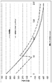
1つ以上の実施の形態によれば、ここに記載されたような積層ガラス系物品は、携帯電話およびタブレットなどの携帯型電子機器用の薄いカバーガラスとして使用することができる。クラッド基板の厚さが65μmから80μmであり、全厚が0.4mmの積層ガラス系物品の応力プロファイルが、図12にプロットされている。実線の曲線はイオン交換による(非積層)残留応力であり、破線の曲線は、積層応力とイオン交換応力の線形和による最終的な残留応力である。圧縮層の深さは、おおよそ65μmから80μmに増加している。 According to one or more embodiments, laminated glass-based articles as described herein can be used as thin cover glasses for portable electronic devices such as mobile phones and tablets. The stress profile of a laminated glass-based article with a clad substrate thickness of 65 μm to 80 μm and a total thickness of 0.4 mm is plotted in FIG. The solid curve is the (non-laminating) residual stress due to ion exchange and the dashed curve is the final residual stress due to the linear sum of the lamination stress and the ion exchange stress. The depth of the compacted layer increases from approximately 65 μm to 80 μm.
図12の応力プロファイルの残留強度が図13にプロットされており、これは、積層サンプルに関する傷サイズによる非単調残留強度を示している。これは、実線により示される非積層ガラスの残留強度と比べられる。この場合、残留強度は、傷深さが80μmより深い場合に大きい。深い傷、例えば、100μmの傷が、好ましくない事象、例えば、硬い表面に落とされたときに、積層カバーガラスに導入された場合、このことは有益である。このガラスを破壊するために、2倍の曲げ応力、200MPa対100MPaがかかるであろう。積層板の場合に中央張力が減少し、中央張力が非積層板の場合と一致する前に、圧縮応力の大きさと層の深さのいくつかの組合せを増加させられることを意味し、これにより深い損傷性能が改善される。このことが一旦行われたら、積層板プロファイルの性能の利点は、非積層板プロファイルに対してさらに増加する。 The residual strength of the stress profile of FIG. 12 is plotted in FIG. 13, which shows non-monotonic residual strength with flaw size for laminated samples. This is compared to the residual strength of unlaminated glass indicated by the solid line. In this case, the residual strength is large when the scratch depth is deeper than 80 μm. This is beneficial if deep scratches, eg, 100 μm scratches, are introduced into the laminated cover glass during undesirable events, eg, when dropped on a hard surface. It would take twice as much bending stress, 200 MPa vs. 100 MPa, to break this glass. This means that the central tension decreases in the laminated case and can be increased for some combination of compressive stress magnitude and layer depth before the central tension matches that in the non-laminated case. Improved deep damage performance. Once this is done, the performance advantage of the laminate profile is further increased over the non-laminate profile.
クラッド基板が50μm厚であり、全厚が0.3mmである、より薄いガラス系物品について、別の実施の形態が図14および図15に示されている。深い傷での残留強度および圧縮層の深さにおける恩恵は、先に述べた0.4mmのガラスと似ている。圧縮層の深さは、おおよそ60μmから75μmに増加している。圧縮層の深さはおおよそ20%増加しており、70μmより深い傷では、残留強度がより良好である。一定のクラッド厚および張力について、エネルギーバランスは、中央圧縮はコアの厚さと反比例することを示しているので、コアの厚さが増加するにつれて、提案された代わりの方法の恩恵は減少する。
Another embodiment is shown in FIGS. 14 and 15 for a thinner glass-based article with a
1つ以上の実施の形態によれば、ガラス系基板の片面における強度の増減は、研磨式リング・オン・リング試験を使用して決定できる。材料の強度は、破壊が生じる応力として定義される。この研磨式リング・オン・リング試験は、平らなガラス試料を試験するための表面強度測定であり、「Standard Test Method for Monotonic Equibiaxial Flexural Sterngth of Advanced Ceramics at Ambient Temperature」と題するASTM C1499-09(2013)が、ここに記載された研磨式リング・オン・リング試験の方法論の基礎を成す。ASTM C1499-09の内容が、ここに全て引用される。1つの実施の形態において、ガラス試料は、リング・オン・リング試験の前に、「Standard Test Methods for Strength of Glass by Flexure (Determination of Modulus of Rupture)」と題するASTM C158-02(2012)の「abrasion Procedures」と題するAnnex A2に記載された方法および装置を使用して、ガラス試料に送達される90グリットの炭化ケイ素(SiC)粒子で研磨される。ASTM C158-02の内容および特に、Annex 2の内容が、ここに全て引用される。
According to one or more embodiments, the increase or decrease in strength on one side of a glass-based substrate can be determined using a polished ring-on-ring test. The strength of a material is defined as the stress at which fracture occurs. This abrasive ring-on-ring test is a surface strength measurement for testing flat glass specimens and is described in ASTM C1499-09 (2013 ) form the basis of the abrasive ring-on-ring test methodology described herein. The contents of ASTM C1499-09 are incorporated herein in full. In one embodiment, the glass sample is subjected to the " 90 grit silicon carbide (SiC) particles delivered to the glass specimen using the method and apparatus described in Annex A2 entitled "Abrasion Procedures". The contents of ASTM C158-02 and in
リング・オン・リング試験の前に、ガラス系物品の表面を、ASTM C158-02の図A2.1に示された装置を使用して、試料の表面欠陥条件を標準化および/または制御するために、ASTM C158-02、Annex 2に記載されたように研磨する。研磨材を、概して、304kPa(44psi)の空気圧を使用して、103kPa(15psi)の荷重でガラス系物品の表面に吹き付ける。気流を確立した後、5cm3の研磨材を漏斗に入れ、研磨材の導入後、5秒間に亘り試料を砂吹き機で磨く。
Prior to the ring-on-ring test, the surface of the glass-based article was annealed using the apparatus shown in Figure A2.1 of ASTM C158-02 to standardize and/or control the surface defect conditions of the specimen. , ASTM C158-02,
研磨式リング・オン・リング試験について、図16に示されたような少なくとも1つの研磨面を有するガラス系物品410を、これも図16に示されたように、異なるサイズの2つの同心のリングの間に配置して、等二軸曲げ強度(すなわち、2つの同心のリングの間の湾曲に曝されたときに材料が維持できる最大応力)を決定する。研磨式リング・オン・リング構成400において、研磨されたガラス系物品410は、直径D2を有する支持リング420により支持されている。ロードセル(図示せず)によって、直径D1を有する荷重リング430を通じて、そのガラス系物品の表面に力Fが印加される。
For the polished ring-on-ring test, a glass-based
荷重リングと支持リングの直径比D1/D2は、約0.2から約0.5の範囲にあるであろう。いくつかの実施の形態において、D1/D2は約0.5である。荷重および支持リング430、420は、支持リングの直径D2の0.5%以内に同心状に揃えるべきである。試験に使用されるロードセルは、選択された範囲内の任意の荷重で±1%以内まで正確であるべきである。いくつかの実施の形態において、試験は、23±2℃の温度および40±10%の相対湿度で行われる。 The diameter ratio D 1 /D 2 of the load ring and the support ring will be in the range of about 0.2 to about 0.5. In some embodiments, D1 / D2 is about 0.5. The load and support rings 430, 420 should be concentrically aligned to within 0.5% of the support ring diameter D2. The load cell used for testing should be accurate to within ±1% at any load within the selected range. In some embodiments, the test is conducted at a temperature of 23±2° C. and a relative humidity of 40±10%.
器具の設計について、荷重リング430の突出面の半径rは、h/2≦r≦3h/2であり、式中、hはガラス系物品410の厚さである。荷重および支持リング430、420は、典型的に、硬度HRc>40の硬化鋼から作られている。研磨式リング・オン・リング器具は市販されている。
For instrument design, the radius r of the protruding surface of
研磨式リング・オン・リング試験の目的の破壊メカニズムは、荷重リング430内の表面430aから発生するガラス系物品410の割れを観察することである。この領域-すなわち、荷重リング430と支持リング420との間-の外で生じる割れは、データ解析から除外する。しかしながら、ガラス系物品410の薄さと高強度のために、サンプルの厚さhの1/2を超える大きい撓みが観察されることがある。したがって、荷重リング430の下から生じる割れの百分率が高いと観察することは、珍しいことではない。リングの内側と下側の両方での応力の発生(歪みゲージ分析により収集)および各サンプルにおける破損の始点を知らずには、応力は正確に計算できない。したがって、研磨式リング・オン・リング試験は、測定反応としての破損時の最大荷重に焦点を当てる。
The intended failure mechanism for abrasive ring-on-ring testing is to observe cracks in glass-based
ガラス系物品の強度は、表面傷の存在に依存する。しかしながら、ガラスの強度は実際には統計に基づくので、存在する既定のサイズの傷の傾向は正確に予測できない。したがって、確率分布を、得られたデータの統計的表示として一般に使用することができる。 The strength of glass-based articles depends on the presence of surface flaws. However, since the strength of glass is actually statistical, the tendency of existing flaws of a given size cannot be accurately predicted. Therefore, probability distributions can generally be used as statistical representations of the data obtained.
1つ以上の実施の形態により記載されたガラス系物品は、様々な最終用途を有し得る。1つ以上の実施の形態において、そのようなガラス系物品としては、建築用板ガラス、自動車のフロントガラスおよび板ガラスが挙げらる。1つ以上の実施の形態によれば、ガラス系物品の互いに反対の表面は、所望の強度および信頼性を有するように設計し、合わせることができる。同様の検討事項が、建築構造に使用される建築用板ガラスに当てはまる。 Glass-based articles described according to one or more embodiments can have a variety of end uses. In one or more embodiments, such glass-based articles include architectural glazings, automotive windshields and glazings. According to one or more embodiments, opposing surfaces of a glass-based article can be designed and matched to have desired strength and reliability. Similar considerations apply to architectural glazings used in building construction.
1つ以上の実施の形態によれば、欠陥寸法は、以下のようにフラクトグラフィーを使用して決定することができる。欠陥寸法は、4点曲げ試験(ASTM C1161:Standard Test Method for Flexural Strength of Advanced Ceramics at Ambient Temperature)またはリング・オン・リング試験(ASTM C1499-15)を使用して壊された試料について、欠陥寸法(原寸法)を決定するために、ASTM基準:C1322-15(Standard Practice for Fractography and Characterization of Fracture Origns in Advanced Ceramics)を使用することによって、フラクトグラフィーを用いて決定することができる。これにより、対象とする用途におけるガラスシートの欠陥寸法分布が確立される。破壊試験に使用される試料が多いほど、試験からの欠陥寸法分布データの信頼が良好になる。あるいは、1つ以上の実施の形態によれば、欠陥寸法は、強度試験および破壊機構解析を用いて決定することができる。ある実施の形態において、強度データは、適切な強度試験(エッジ強度に関する4点曲げおよび内部強度に関するリング・オン・リング)を使用して実行可能なだけ多くの試料を使用して得られる。適切な破壊解析モデル(解析または有限要素解析)を使用して、強度試験において試料の破損を生じたに違いない欠陥寸法を予測することができる。これにより、特定の欠陥寸法、形状、および位置が推測され、それゆえ、この手法は、フラクトグラフィー手法ほど正確ではないが、欠陥個体数を確立するのがより容易である。 According to one or more embodiments, defect size can be determined using fractography as follows. The defect size is measured using the 4-point bend test (ASTM C1161: Standard Test Method for Flexural Strength of Advanced Ceramics at Ambient Temperature) or the ring-on-ring test (ASTM C1499-15) for broken specimens. (original dimensions) can be determined using fractography by using ASTM standard: C1322-15 (Standard Practice for Fractography and Characterization of Fracture Origns in Advanced Ceramics). This establishes the defect size distribution of the glass sheet for the intended application. The more samples that are used for destructive testing, the better the confidence in the defect size distribution data from testing. Alternatively, according to one or more embodiments, defect size can be determined using strength testing and failure mechanism analysis. In one embodiment, strength data is obtained using as many samples as practicable using appropriate strength tests (4-point bending for edge strength and ring-on-ring for internal strength). A suitable failure analysis model (analysis or finite element analysis) can be used to predict the defect size that would have caused the sample to fail in the strength test. This infers specific defect sizes, shapes, and locations, so while this technique is not as accurate as the fractography technique, it is easier to establish defect populations.
強化されたガラス系基板は、様々な異なる過程を使用して提供することができる。例えば、例示のガラス系基板形成方法としては、フロートガラス法、およびフュージョンドロー法やスロットドロー法などのダウンドロー法が挙げられる。フロートガラス法により調製されるガラス系基板は、滑らかな表面および均一な厚さにより特徴付けられ、溶融金属、典型的に、スズの床上に溶融ガラスを浮かせることによって製造される。例示の過程において、溶融スズ床の表面上に供給された溶融ガラスが、浮遊するガラスリボンを形成する。そのガラスリボンがスズ浴に沿って流動するにつれて、ガラスリボンがスズからローラ上に持ち上げられる固体のガラス系基板に固化するまで、温度が徐々に低下する。一旦浴から離れたら、ガラス系基板は、さらに冷却し、徐冷して、内部応力を減少させることができる。 A toughened glass-based substrate can be provided using a variety of different processes. For example, exemplary glass-based substrate formation methods include float glass methods and down-draw methods such as fusion draw and slot draw. Glass-based substrates prepared by the float glass method are characterized by smooth surfaces and uniform thickness and are produced by floating molten glass on a bed of molten metal, typically tin. In an exemplary process, molten glass fed onto the surface of a bed of molten tin forms a floating glass ribbon. As the glass ribbon flows along the tin bath, the temperature is gradually reduced until the glass ribbon solidifies from the tin into a solid glass-based substrate that is lifted onto a roller. Once removed from the bath, the glass-based substrate can be further cooled and annealed to reduce internal stress.
ダウンドロー法により、比較的無垢な表面を有する均一な厚さを持つガラス系基板が製造される。そのガラス系基板の平均曲げ強度は表面傷の量とサイズにより制御されるので、接触が最小であった無垢な表面は、より高い初期強度を有する。次いで、この高強度のガラス系基板をさらに強化(例えば、化学的に)すると、得られた強度は、ラップ仕上げされ、研磨された表面を有するガラス系基板の強度よりも高くなり得る。ダウンドロー法により製造されたガラス系基板は、約2mm未満の厚さまで延伸されることがある。その上、ダウンドロー法により製造されたガラス系基板は、費用のかかる研削および研磨を使用せずに、最終用途に使用できる非常に平らで滑らかな表面を有する。 The down-draw process produces a glass-based substrate of uniform thickness with a relatively pristine surface. Since the average flexural strength of the glass-based substrate is controlled by the amount and size of surface flaws, a pristine surface with minimal contact has a higher initial strength. This high-strength glass-based substrate is then further strengthened (eg, chemically) and the resulting strength can be higher than that of a glass-based substrate having a lapped and polished surface. Glass-based substrates manufactured by the down-draw method may be drawn to a thickness of less than about 2 mm. Moreover, glass-based substrates produced by the down-draw method have very flat and smooth surfaces that can be used in end-use applications without the use of costly grinding and polishing.
フュージョンドロー法は、例えば、溶融ガラス原材料を受け容れるための通路を有する延伸槽を使用する。この通路は、通路の両側で通路の長さに沿って上部で開いた堰を有する。この通路が溶融材料で満たされると、溶融ガラスは堰を溢れる。この溶融ガラスは、重力のために、2つの流動するガラス膜として、延伸槽の外面を流下する。この延伸槽のこれらの外面は、延伸槽の下のエッジで接合するように、下方かつ内方に延在する。2つの流動するガラス膜は、このエッジで接合して、融合し、1つの流動するガラス系基板を形成する。このフュージョンドロー法は、通路を越えて流れる2つのガラス膜が互いに融合するので、得られるガラス系基板の外面のいずれも、装置のどの部分とも接触しないという利点を提示する。それゆえ、フュージョンドロー法により製造されたガラス系基板の表面特性は、そのような接触によって影響を受けない。 The fusion draw process, for example, uses a drawing vessel having passages for receiving molten glass raw materials. The passageway has weirs open at the top along the length of the passageway on either side of the passageway. As this passage fills with molten material, the molten glass overflows the weir. This molten glass flows down the outer surface of the draw bath as two flowing glass films due to gravity. These outer surfaces of the drawing trough extend downward and inward to join at the lower edge of the drawing trough. The two flowing glass films join at this edge and fuse to form one flowing glass-based substrate. This fusion draw method presents the advantage that none of the outer surfaces of the resulting glass-based substrate come into contact with any part of the device, as the two glass films flowing over the channels fuse together. Therefore, the surface properties of glass-based substrates produced by the fusion draw method are not affected by such contact.
スロットドロー法は、フュージョンドロー法とは異なる。スロットドロー法において、溶融原材料が延伸槽に供給される。この延伸槽の底部には、開いたスロットであって、そのスロットの長さに延在するノズルを有するスロットがある。溶融ガラスが、スロット/ノズルを通って流れ、連続基板として、徐冷領域へと下方に延伸される。 The slot draw method is different from the fusion draw method. In the slot draw process, molten raw material is fed into a draw bath. At the bottom of the draw bath there is an open slot with a nozzle extending the length of the slot. Molten glass flows through the slots/nozzles and is drawn downward as a continuous substrate into the anneal zone.
いくつかの実施の形態において、ガラス系基板に使用される組成物に、Na2SO4、NaCl、NaF、NaBr、K2SO4、KCl、KF、KBr、およびSnO2を含む群から選択される少なくとも1種類の清澄剤が0~2モル%配合されることがある。 In some embodiments, the composition used for the glass - based substrate is selected from the group comprising Na2SO4 , NaCl, NaF, NaBr, K2SO4 , KCl, KF, KBr, and SnO2 . 0 to 2 mol % of at least one refining agent may be blended.
ガラス系基板は、一旦形成されたら、強化して、強化されたガラス系基板を形成して強化基板を提供することができる。ガラスセラミック基板も、ガラス系基板と同様の様式で強化できることに留意のこと。ここに用いられているように、「強化基板」という用語は、例えば、ガラス系またはガラス基板の表面にあるより小さいイオンをより大きいイオンでイオン交換することによって、化学強化されたガラス系基板またはガラス基板を称することができる。しかしながら、先に述べたように、強化ガラス基板を形成するために、熱的焼入れまたは熱強化など、当該技術分野で公知の熱的強化方法も利用してよい。いくつかの実施の形態において、それらの基板は、化学強化過程および熱的強化過程の組合せを使用して強化されることがある。 Once formed, the glass-based substrate can be strengthened to form a strengthened glass-based substrate to provide a strengthened substrate. Note that glass-ceramic substrates can also be strengthened in a similar manner as glass-based substrates. As used herein, the term "strengthened substrate" refers to a glass-based substrate or glass-based substrate that has been chemically strengthened, for example, by ion-exchanging smaller ions on the surface of the glass-based or glass substrate with larger ions. A glass substrate can be referred to. However, as noted above, thermal strengthening methods known in the art, such as thermal tempering or heat strengthening, may also be utilized to form tempered glass substrates. In some embodiments, the substrates may be strengthened using a combination of chemical and thermal strengthening processes.
強化されたガラス系基板において、ガラスの表面に圧縮応力(CS)が、そして中央には張力(中央張力またはCT)がある応力プロファイルが存在する。1つ以上の実施の形態によれば、そのスクリーンカバーは、熱的に強化されても、化学強化されても、または熱的強化と化学強化の組合せが施されても差し支えない。ここに用いられているように、「熱的に強化された」とは、基板の強度を改善するために、熱処理された基板を称し、「熱的に強化された」は、焼入れ基板および熱強化された基板、例えば、焼入れガラスおよび熱強化ガラスを含む。焼入れガラスは、加速冷却過程を含み、これにより、ガラスにより高い表面圧縮および/またはエッジ圧縮が生じる。表面圧縮の程度に影響する要因としては、空気クエンチ温度、体積、および少なくとも約68.9MPa(10,000ポンド毎平方インチ(psi))の表面圧縮を生じる他の変数が挙げられる。焼入れガラスは、典型的に、徐冷または未処理ガラスよりも4から5倍強力である。熱強化ガラスは、焼入れガラスよりも遅い冷却によって製造され、これにより、表面での圧縮強度が低くなり、熱強化ガラスは、徐冷または未処理ガラスの約2倍ほど強力である。 In tempered glass-based substrates, there is a stress profile with compressive stress (CS) at the surface of the glass and tension in the center (central tension or CT). According to one or more embodiments, the screen covering can be thermally strengthened, chemically strengthened, or a combination of thermal and chemical strengthening. As used herein, "thermally strengthened" refers to a substrate that has been heat treated to improve the strength of the substrate; Includes tempered substrates such as tempered glass and heat strengthened glass. Tempered glass involves an accelerated cooling process that causes the glass to experience high surface and/or edge compression. Factors that affect the degree of surface compression include air quench temperature, volume, and other variables that produce a surface compression of at least about 10,000 pounds per square inch (psi). Tempered glass is typically 4 to 5 times stronger than annealed or untreated glass. Heat-strengthened glass is produced by cooling slower than tempered glass, which results in lower compressive strength at the surface, and heat-strengthened glass is about twice as strong as annealed or untreated glass.
前記コアおよびクラッド基板に使用してよいガラスの例としては、アルカリアルミノケイ酸塩ガラス組成物またはアルカリアルミノホウケイ酸塩ガラス組成物が挙げられるが、他のガラス組成物も考えられる。そのようなガラス組成物は、イオン交換可能であると特徴付けられる。ここに用いられているように、「イオン交換可能」とは、その組成物から作られた基板が、その基板の表面またはその近くに位置する陽イオンを、サイズがより大きいか小さい同じ価数の陽イオンと交換することができることを意味する。ガラス組成物の一例は、SiO2、B2O3、およびNa2Oを含み、ここで、(SiO2+B2O3)≧約66モル%、およびNa2O≧約9モル%である。適切なガラス組成物は、いくつかの実施の形態において、K2O、MgO、およびCaOの内の少なくとも1つをさらに含む。特定の実施の形態において、基板に使用されるガラス組成物は、61~75モル%のSiO2、7~15モル%のAl2O3、0~12モル%のB2O3、9~21モル%のNa2O、0~4モル%のK2O、0~7モル%のMgO、および0~3モル%のCaOを含み得る。 Examples of glasses that may be used for the core and clad substrates include alkali aluminosilicate glass compositions or alkali aluminoborosilicate glass compositions, although other glass compositions are also contemplated. Such glass compositions are characterized as ion-exchangeable. As used herein, "ion-exchangeable" means that a substrate made from the composition allows cations located at or near the surface of the substrate to be exchanged with cations of the same valence of greater or lesser size. means that it can be exchanged for the cation of An example glass composition includes SiO2 , B2O3 , and Na2O , where ( SiO2 + B2O3) > about 66 mol% and Na2O > about 9 mol%. . Suitable glass compositions, in some embodiments, further include at least one of K2O, MgO, and CaO. In certain embodiments, the glass composition used for the substrate is 61-75 mol % SiO 2 , 7-15 mol % Al 2 O 3 , 0-12 mol % B 2 O 3 , 9- It may contain 21 mol % Na 2 O, 0-4 mol % K 2 O, 0-7 mol % MgO, and 0-3 mol % CaO.
前記基板に適した別の例示のガラス組成物は、60~70モル%のSiO2、6~14モル%のAl2O3、0~15モル%のB2O3、0~15モル%のLi2O、0~20モル%のNa2O、0~10モル%のK2O、0~8モル%のMgO、0~10モル%のCaO、0~5モル%のZrO2、0~1モル%のSnO2、0~1モル%のCeO2、50ppm未満のAs2O3、および50ppm未満のSb2O3を含み、ここで、12モル%≦(Li2O+Na2O+K2O)≦20モル%、および0モル%≦(MgO+CaO)≦10モル%である。 Another exemplary glass composition suitable for the substrate is 60-70 mol % SiO 2 , 6-14 mol % Al 2 O 3 , 0-15 mol % B 2 O 3 , 0-15 mol % Li 2 O, 0-20 mol % Na 2 O, 0-10 mol % K 2 O, 0-8 mol % MgO, 0-10 mol % CaO, 0-5 mol % ZrO 2 , 0-1 mol % SnO 2 , 0-1 mol % CeO 2 , less than 50 ppm As 2 O 3 , and less than 50 ppm Sb 2 O 3 , wherein 12 mol %≦(Li 2 O+Na 2 O+K 2 O)≦20 mol %, and 0 mol %≦(MgO+CaO)≦10 mol %.
前記基板に適したさらに別の例示のガラス組成物は、63.5~66.5モル%のSiO2、8~12モル%のAl2O3、0~3モル%のB2O3、0~5モル%のLi2O、8~18モル%のNa2O、0~5モル%のK2O、1~7モル%のMgO、0~2.5モル%のCaO、0~3モル%のZrO2、0.05~0.25モル%のSnO2、0.05~0.5モル%のCeO2、50ppm未満のAs2O3、および50ppm未満のSb2O3を含み、ここで、14モル%≦(Li2O+Na2O+K2O)≦18モル%、および2モル%≦(MgO+CaO)≦7モル%である。 Yet another exemplary glass composition suitable for the substrate is 63.5-66.5 mol % SiO 2 , 8-12 mol % Al 2 O 3 , 0-3 mol % B 2 O 3 , 0-5 mol % Li 2 O, 8-18 mol % Na 2 O, 0-5 mol % K 2 O, 1-7 mol % MgO, 0-2.5 mol % CaO, 0- 3 mol % ZrO 2 , 0.05-0.25 mol % SnO 2 , 0.05-0.5 mol % CeO 2 , less than 50 ppm As 2 O 3 , and less than 50 ppm Sb 2 O 3 . where 14 mol %≦(Li 2 O+Na 2 O+K 2 O)≦18 mol % and 2 mol %≦(MgO+CaO)≦7 mol %.
特定の実施の形態において、前記基板に適したアルカリアルミノケイ酸塩ガラス組成物は、アルミナ、少なくとも1種類のアルカリ金属およびいくつかの実施の形態において、50モル%超のSiO2、他の実施の形態において、少なくとも58モル%のSiO2、そしてさらに他の実施の形態において、少なくとも60モル%のSiO2を含み、比((Al2O3+B2O3)/Σ改質剤)>1であり、この比において、成分はモル%で表され、改質剤はアルカリ金属酸化物である。このガラス組成物は、特定の実施の形態において、58~72モル%のSiO2、9~17モル%のAl2O3、2~12モル%のB2O3、8~16モル%のNa2O、および0~4モル%のK2Oを含み、比((Al2O3+B2O3)/Σ改質剤)>1である。 In certain embodiments, the alkali aluminosilicate glass composition suitable for the substrate comprises alumina, at least one alkali metal and in some embodiments greater than 50 mol % SiO 2 , in other embodiments In embodiments, at least 58 mol % SiO 2 , and in still other embodiments at least 60 mol % SiO 2 , wherein the ratio ((Al 2 O 3 +B 2 O 3 )/Σ Modifier)>1. where the component is expressed in mole % and the modifier is the alkali metal oxide. The glass composition comprises, in certain embodiments, 58-72 mol % SiO 2 , 9-17 mol % Al 2 O 3 , 2-12 mol % B 2 O 3 , 8-16 mol % Na 2 O, and 0-4 mol % K 2 O with a ratio ((Al 2 O 3 +B 2 O 3 )/Σ modifier)>1.
さらに別の実施の形態において、前記基板は、64~68モル%のSiO2、12~16モル%のNa2O、8~12モル%のAl2O3、0~3モル%のB2O3、2~5モル%のK2O、4~6モル%のMgO、および0~5モル%のCaOを含む。 In yet another embodiment, the substrate comprises 64-68 mol % SiO 2 , 12-16 mol % Na 2 O, 8-12 mol % Al 2 O 3 , 0-3 mol % B 2 O 3 , 2-5 mol % K 2 O, 4-6 mol % MgO, and 0-5 mol % CaO.
代わりの実施の形態において、前記基板は、2モル%以上のAl2O3および/またはZrO2、もしくは4モル%以上のAl2O3および/またはZrO2を含むアルカリアルミノケイ酸塩ガラス組成物を含むことがある。 In alternative embodiments, the substrate is an alkali aluminosilicate glass composition comprising 2 mol % or more Al 2 O 3 and/or ZrO 2 , or 4 mol % or more Al 2 O 3 and/or ZrO 2 may contain
ここに記載された強化基板は、イオン交換過程によって化学強化されることがある。イオン交換過程において、一般に、ガラスまたはガラスセラミック基板を所定の期間に亘り溶融塩浴中に浸漬することによって、ガラスまたはガラスセラミック基板の表面またはその近くにあるイオンが、その塩浴からのより大きい金属イオンと交換される。1つの実施の形態において、溶融塩浴の温度は約400~430℃であり、その所定の期間は約4から約12時間である。より大きいイオンをそのガラスまたはガラスセラミック基板中に含ませると、その基板の表面に近い領域またはその表面の領域およびそれと隣接した領域に圧縮応力を生じることによって、基板が強化される。その圧縮応力と釣り合うために、基板の中央領域すなわちその表面からある距離にある領域内に、対応する引張応力が誘発される。この強化過程を利用したガラスまたはガラスセラミック基板は、化学強化またはイオン交換されたガラスまたはガラスセラミック基板とより詳しく記載されることがある。 The reinforced substrates described herein may be chemically strengthened by an ion exchange process. In the ion-exchange process, generally by immersing a glass or glass-ceramic substrate in a molten salt bath for a predetermined period of time, ions at or near the surface of the glass or glass-ceramic substrate are more readily absorbed than ions from the salt bath. exchanged with metal ions. In one embodiment, the temperature of the molten salt bath is about 400-430° C. and the predetermined time period is about 4 to about 12 hours. The inclusion of larger ions into the glass or glass-ceramic substrate strengthens the substrate by creating compressive stresses near or adjacent to the surface of the substrate. To balance the compressive stress, a corresponding tensile stress is induced in the central region of the substrate, ie, the region at some distance from its surface. Glass or glass-ceramic substrates that utilize this strengthening process are sometimes more specifically described as chemically strengthened or ion-exchanged glass or glass-ceramic substrates.
一例において、強化されるガラスまたはガラスセラミック基板中のナトリウムイオンは、硝酸カリウム塩浴などの溶融浴からのカリウムイオンにより交換されるが、ルビジウムまたはセシウムなど、原子半径がより大きい他のアルカリ金属イオンが、ガラス中のより小さいアルカリ金属イオンを置換しても差し支えない。特定の実施の形態によれば、ガラスまたはガラスセラミック中のより小さいアルカリ金属イオンが、Ag+イオンにより置換されて、抗菌効果を提供することができる。同様に、以下に限られないが、硫酸塩、リン酸塩、ハロゲン化物などの他のアルカリ金属塩をイオン交換過程に使用してもよい。 In one example, sodium ions in the glass or glass-ceramic substrate to be strengthened are replaced by potassium ions from a molten bath such as a potassium nitrate salt bath, while other alkali metal ions with larger atomic radii such as rubidium or cesium are exchanged. , can replace smaller alkali metal ions in the glass. According to certain embodiments, smaller alkali metal ions in the glass or glass-ceramic can be replaced by Ag + ions to provide an antimicrobial effect. Similarly, other alkali metal salts such as, but not limited to, sulfates, phosphates, halides, etc. may be used in the ion exchange process.
強化されたガラス系基板において、ガラスの表面に圧縮応力(CS)が、そして中央には張力(中央張力またはCT)がある応力プロファイルが存在する。ガラス網目構造が緩和できる温度より低い温度でより小さいイオンがより大きいイオンで置換されると、強化基板の表面に亘りイオン分布が生じ、これにより、応力プロファイルがもたらされる。入ってくるイオンの体積がより大きいと、強化基板の表面に圧縮応力(CS)が、中央に張力(中央張力またはCT)が生じる。圧縮応力(表面CSを含む)は、有限会社折原製作所(日本国)により製造されているFSM-6000などの市販の計器を使用して表面応力計(FSM)により測定される。表面応力測定は、ガラスの複屈折に関連する、応力光学係数(SOC)の精密測定に依存する。次に、SOCは、その内容がここに全て引用される、「Standard Test Method for Measurement of Glass Stress-Optical Coefficient」と題する、ASTM基準C770-16に記載された手順C(ガラスディスク法)にしたがって測定される。1つ以上の実施の形態において、コアおよび/またはクラッドに使用されるガラス系基板は、750MPa以上、例えば、800MPa以上、850MPa以上、900MPa以上、1000MPa以上、1150MPa以上、または1200MPaの表面圧縮応力を有し得る。 In tempered glass-based substrates, there is a stress profile with compressive stress (CS) at the surface of the glass and tension in the center (central tension or CT). The replacement of smaller ions by larger ions at temperatures below the temperature at which the glass network can relax results in an ion distribution across the surface of the strengthened substrate, which results in a stress profile. A larger volume of incoming ions creates a compressive stress (CS) on the surface of the reinforcing substrate and a tensile stress in the center (central tension or CT). Compressive stress (including surface CS) is measured by a surface stress meter (FSM) using a commercially available instrument such as the FSM-6000 manufactured by Orihara Seisakusho Ltd. (Japan). Surface stress measurements rely on precise measurements of the stress optical coefficient (SOC), which is related to the birefringence of the glass. The SOC is then tested according to Procedure C (Glass Disc Method) set forth in ASTM Standard C770-16 entitled "Standard Test Method for Measurement of Glass Stress-Optical Coefficient", the contents of which are hereby incorporated by reference in its entirety. measured. In one or more embodiments, the glass-based substrate used for the core and/or cladding exhibits a surface compressive stress of 750 MPa or greater, such as 800 MPa or greater, 850 MPa or greater, 900 MPa or greater, 1000 MPa or greater, 1150 MPa or greater, or 1200 MPa. can have
ここに用いられているように、DOLは、ここに記載された化学強化されたアルカリアミノケイ酸塩ガラス物品中の応力が圧縮から引張に変化する深さを意味する。DOLは、イオン交換処理に応じて、FSMまたは散乱光偏光器(SCALP)により測定することができる。ガラス物品における応力が、ガラス物品中にカリウムイオンを交換することによって生じる場合、DOLを測定するために、FSMが使用される。応力が、ガラス物品中にナトリウムイオンを交換することによって生じる場合、DOLを測定するために、SCALPが使用される。ガラス物品における応力が、ガラス中にカリウムイオンとナトリウムイオンの両方を交換することによって生じる場合、DOLはSCALPにより測定される。何故ならば、ナトリウムの交換深さはDOLを表し、カリウムイオンの交換深さは、圧縮応力の大きさの変化(圧縮から引張への応力の変化ではない)を表すと考えられるからである;そのようなガラス物品におけるカリウムイオンの交換深さは、FSMにより測定される。 As used herein, DOL means the depth at which stress changes from compression to tension in the chemically strengthened alkali aminosilicate glass articles described herein. DOL can be measured by FSM or scattered light polarizer (SCALP), depending on the ion exchange treatment. FSM is used to measure DOL when the stress in the glass article is caused by exchanging potassium ions in the glass article. SCALP is used to measure DOL when the stress is caused by exchanging sodium ions in the glass article. DOL is measured by SCALP when the stress in the glass article is caused by the exchange of both potassium and sodium ions in the glass. because it is believed that the sodium exchange depth represents the DOL and the potassium ion exchange depth represents the change in magnitude of compressive stress (not the change in stress from compression to tension); The exchange depth of potassium ions in such glass articles is measured by FSM.
屈折近視野(RNF)法またはSCALPを使用して、応力プロファイルを測定してもよい。応力プロファイルを測定するために、RNF法が使用される場合、SCALPにより与えられる最大CT値がRNF法に利用される。詳しくは、RNFにより測定される応力プロファイルは、SCALP測定により与えられる最大CT値に対して力平衡され、較正される。このRNF法は、ここに全てが引用される、「Systems and methods for measuring a profile characteristic of a glass sample」と題する米国特許第8854623号明細書に記載されている。詳しくは、RNF法は、基準ブロックに隣接してガラス物品を配置する工程、1Hzと50Hzの間の率で直交偏光の間で切り換えられる偏光切替光線を生成する工程、その偏光切替光線の出力量を測定する工程、および偏光切替基準信号を生成する工程を含み、直交偏光の各々の出力の測定量は互いの50%以内にある。この方法は、偏光切替光線を、ガラス試料中の異なる深さについて、ガラス試料および基準ブロックに透過させ、次いで、リレー光学系を使用して、透過した偏光切替光線を信号光検出器に中継する工程をさらに含み、その信号光検出器は偏光切替検出器信号を生成する。この方法は、検出器信号を基準信号で割って、正規化検出器信号を形成する工程、およびその正規化検出器信号からガラス試料のプロファイル特徴を決定する工程も含む。 A refractive near-field (RNF) method or SCALP may be used to measure the stress profile. When the RNF method is used to measure the stress profile, the maximum CT value given by SCALP is used for the RNF method. Specifically, the stress profile measured by RNF is force balanced and calibrated to the maximum CT value given by the SCALP measurement. This RNF method is described in US Pat. No. 8,854,623, entitled "Systems and methods for measuring a profile characteristic of a glass sample," which is fully incorporated herein by reference. Specifically, the RNF method comprises the steps of placing a glass article adjacent to a reference block, generating a polarization-switched beam that is switched between orthogonal polarizations at a rate between 1 Hz and 50 Hz, and outputting the polarization-switched beam and generating a polarization switching reference signal, wherein the measured quantities of the outputs of each of the orthogonal polarizations are within 50% of each other. This method transmits the polarization-switched light beam through the glass sample and the reference block for different depths in the glass sample, and then uses relay optics to relay the transmitted polarization-switched light beam to the signal photodetector. Further comprising the step, wherein the signal photodetector produces a polarization switched detector signal. The method also includes dividing the detector signal by a reference signal to form a normalized detector signal, and determining profile characteristics of the glass sample from the normalized detector signal.
1つ以上の実施の形態において、米国特許出願公開第2015/0239775号明細書に記載されたガラス組成物を使用して、ここに記載されたようなガラス基板を製造してもよい。米国特許出願公開第2015/0239775号明細書には、表面から比較的浅い深さまで延在し、急勾配を有する第1の部分、およびその浅い深さから圧縮深さまで延在する第2の部分の2つの線形部分を含む圧縮応力プロファイルを有するガラス物品が記載されている。 In one or more embodiments, the glass compositions described in US Patent Application Publication No. 2015/0239775 may be used to produce glass substrates as described herein. U.S. Patent Application Publication No. 2015/0239775 discloses a steep first portion extending from the surface to a relatively shallow depth and a second portion extending from the shallow depth to a compression depth. A glass article is described that has a compressive stress profile that includes two linear portions of .
イオン交換過程は、典型的に、ガラス中のより小さいイオンと交換されるべきより大きいイオンを含有する溶融塩浴中にガラス系物品を浸漬することによって行われる。以下に限られないが、浴の組成と温度、浸漬時間、1つの塩浴(または複数の塩浴)中のガラスの浸漬回数、多数の塩浴の使用、徐冷、洗浄などの追加の工程を含む、イオン交換過程のパラメータは、一般に、ガラスの組成および強化操作により生じるガラスの所望の層の深さと圧縮応力により決定されることが当業者に認識されるであろう。一例として、アルカリ金属を含有するガラスのイオン交換は、以下に限られないが、より大きいアルカリ金属イオンの硝酸塩、硫酸塩、および塩化物などの塩を含有する少なくとも1つの溶融浴中の浸漬により行うことができる。溶融塩浴の温度は、典型的に、約380℃から約450℃の範囲にある一方で、浸漬時間は、約15分から約40時間に及ぶ。しかしながら、先に記載したものと異なる温度および浸漬時間も使用してよい。 The ion exchange process is typically performed by immersing the glass-based article in a molten salt bath containing larger ions to be exchanged for smaller ions in the glass. Additional steps such as, but not limited to, bath composition and temperature, immersion time, number of times glass is immersed in one salt bath (or multiple salt baths), use of multiple salt baths, slow cooling, washing, etc. It will be appreciated by those skilled in the art that the parameters of the ion exchange process, including, are generally determined by the composition of the glass and the desired layer depth and compressive stress of the glass resulting from the tempering operation. By way of example, ion exchange of glasses containing alkali metals is by immersion in at least one molten bath containing salts such as, but not limited to, nitrates, sulfates, and chlorides of larger alkali metal ions. It can be carried out. The temperature of the molten salt bath typically ranges from about 380° C. to about 450° C., while immersion times range from about 15 minutes to about 40 hours. However, temperatures and immersion times different from those previously described may also be used.
それに加え、複数の浸漬の間に洗浄工程および/または徐冷工程が行われる、多数のイオン交換浴中にガラスが浸漬されるイオン交換過程の非限定例が、異なる濃度の複数の塩浴中の浸漬を含む多数の連続したイオン交換処理によって、ガラスが強化される、2008年7月11日に出願された米国仮特許出願第61/079995号からの優先権を主張する、「Glass with Compressive Surface for Consumer Applications」と題する、2013年10月22日に発行されたDouglas C. Allan等による米国特許第8561429号明細書、およびガラスが、流出イオンにより希釈された第1の浴中のイオン交換と、その後の、第1の浴より小さい濃度の流出イオンを有する第2の浴中の浸漬とにより強化される、2008年7月29日に出願された米国仮特許出願第61/084398号からの優先権を主張する、「Dual Stage Ion Exchange for Chemical Strengthening of Glass」と題する、2012年11月20日に発行された、Christopher M. Lee等による米国特許第8312739号明細書に記載されている。米国特許第8561429号、および同第8312739号の各明細書が、ここに全て引用される。 In addition, a non-limiting example of an ion-exchange process in which the glass is immersed in multiple ion-exchange baths with washing and/or annealing steps between the multiple immersions is in multiple salt baths of different concentrations. Claiming priority from U.S. Provisional Patent Application No. 61/079995, filed Jul. 11, 2008, "Glass with Compressive U.S. Patent No. 8,561,429 to Douglas C. Allan et al., entitled "Surface for Consumer Applications", issued Oct. 22, 2013, and ion exchange in a first bath in which the glass is diluted with effluent ions. and subsequent immersion in a second bath having a lower concentration of effluent ions than the first bath, from U.S. Provisional Patent Application No. 61/084398, filed July 29, 2008 US Patent No. 8,312,739 by Christopher M. Lee et al. . US Pat. Nos. 8,561,429 and 8,312,739 are fully incorporated herein by reference.
圧縮応力は、例えば、ガラス系物品の外側領域中の複数の第1の金属イオンが、その外側領域が複数の第2の金属イオンを含むようにその複数の第2の金属イオンと交換される、本明細書中に先に記載されたイオン交換過程によって、ガラス系物品を化学強化することによって生じる。第1の金属イオンの各々は第1のイオン半径を有し、第2の金属イオンの各々は第2のイオン半径を有する。第2のイオン半径は第1のイオン半径より大きく、外側領域内のより大きい第2のアルカリ金属イオンの存在により、外側領域に圧縮応力が生じる。 The compressive stress, for example, exchanges the plurality of first metal ions in the outer region of the glass-based article with the plurality of second metal ions such that the outer region includes the plurality of second metal ions. , by chemically strengthening the glass-based article by the ion-exchange process previously described herein. Each of the first metal ions has a first ionic radius and each of the second metal ions has a second ionic radius. The second ionic radius is greater than the first ionic radius and the presence of the larger second alkali metal ions in the outer region creates a compressive stress in the outer region.
第1の金属イオンおよび第2の金属イオンの少なくとも一方は、アルカリ金属のイオンである。第1のイオンは、リチウム、ナトリウム、カリウム、およびルビジウムのイオンであることがある。第2の金属イオンは、第2のアルカリ金属イオンが第1のアルカリ金属イオンのイオン半径よりも大きいイオン半径を有するという条件で、ナトリウム、カリウム、ルビジウム、およびセシウムの内の1つのイオンであることがある。 At least one of the first metal ion and the second metal ion is an alkali metal ion. The first ions may be lithium, sodium, potassium, and rubidium ions. The second metal ion is one of sodium, potassium, rubidium, and cesium, provided that the second alkali metal ion has an ionic radius greater than the ionic radius of the first alkali metal ion. Sometimes.
ここに開示されたガラス系物品は、ディスプレイを備えた物品(またはディスプレイ物品)(例えば、携帯電話、タブレット、コンピュータ、ナビゲーションシステムなどを含む家庭用電化製品)、建築物品、輸送物品(例えば、自動車、列車、航空機、船舶など)、電化製品、またはある程度の透明性、耐引掻性、耐摩耗性またはその組合せを必要とする任意の物品などの別の物品に組み込まれることがある。ここに開示されたガラス系物品のいずれかを組み込んだ例示の物品が、図17Aおよび17Bに示されている。詳しくは、図17Aおよび17Bは、前面1704、背面1706、および側面1708を有する筐体1702;その筐体内に少なくとも部分的に内部にあるまたは完全に中にある電気部品(図示せず)であって、少なくとも、制御装置、メモリ、および筐体の前面にまたはそれに隣接したディスプレイ1710を含む電気部品;およびディスプレイ上にあるように、筐体の前面またはその上にあるカバー基板1712を備えた家庭用電子機器1700を示している。いくつかの実施の形態において、カバー基板1712は、ここに開示されたガラス系物品のいずれを含んでもよい。先の記載は様々な実施の形態に関するが、本開示の他の実施の形態とさらに別の実施の形態も、その基本的な範囲から逸脱せずに考案することができ、その範囲は、以下の特許請求の範囲によって決定される。
The glass -based articles disclosed herein include articles with displays (or display articles) (e.g., consumer electronics including mobile phones, tablets, computers, navigation systems, etc.), architectural articles, transportation articles (e.g., automobiles, trains, aircraft, ships, etc.), appliances, or another article such as any article requiring a degree of transparency, scratch resistance, abrasion resistance, or a combination thereof. An exemplary article incorporating any of the glass -based articles disclosed herein is shown in FIGS. 17A and 17B. Specifically, FIGS. 17A and 17B illustrate a
以下、本発明の好ましい実施形態を項分け記載される。 Preferred embodiments of the present invention are described below itemized.
実施形態1
ガラス系物品において、
約0.1ミリメートルから3ミリメートルの範囲の基板厚(t)を規定する、第1の表面および該第1の表面と反対の第2の表面を有するガラス系基板であって、前記ガラス系物品の該第1の表面で第1の圧縮応力CS極大値を、該第1の表面から少なくとも25μmの深さで第2の局所CS極大値を有する、圧縮深さ(DOC)まで延在する圧縮領域を有するガラス系基板、
を備え、
前記ガラス系基板は、第一面と第二面を有するガラス系コア基板を含み、該ガラス系コア基板はガラス系の第1のクラッド基板およびガラス系の第2のクラッド基板の間に挟まれており、該第1のクラッド基板は前記第一面に直接結合され、該第2のクラッド基板は前記第二面に直接結合されている、ガラス系物品。
Embodiment 1
In glass-based articles,
A glass-based substrate having a first surface and a second surface opposite the first surface defining a substrate thickness (t) in the range of about 0.1 millimeters to 3 millimeters, said glass-based article a compression extending to a depth of compression (DOC) having a first compressive stress CS maximum at said first surface of and a second local CS maximum at a depth of at least 25 μm from said first surface of a glass-based substrate having regions;
with
The glass-based substrate includes a glass-based core substrate having a first surface and a second surface, the glass-based core substrate being sandwiched between a glass-based first clad substrate and a glass-based second clad substrate. wherein the first clad substrate is directly bonded to the first surface and the second clad substrate is directly bonded to the second surface.
実施形態2
前記ガラス系物品は、0.1mmから2mmの範囲の厚さを有する、実施形態1に記載のガラス系物品。
2. A glass-based article according to embodiment 1, wherein the glass-based article has a thickness ranging from 0.1 mm to 2 mm.
実施形態3
前記第2の局所CS極大値が前記第1の表面から少なくとも50μmの深さにある、実施形態1または2に記載のガラス系物品。
Embodiment 3
3. A glass-based article according to
実施形態4
前記第2の局所CS極大値が前記第1の表面から少なくとも75μmの深さにある、実施形態3に記載のガラス系物品。
4. A glass-based article according to embodiment 3, wherein said second local CS maximum is at a depth of at least 75 μm from said first surface.
実施形態5
前記第2の局所CS極大値が前記第1の表面から少なくとも100μmの深さにある、実施形態3に記載のガラス系物品。
Embodiment 5
4. A glass-based article according to embodiment 3, wherein said second local CS maximum is at a depth of at least 100 μm from said first surface.
実施形態6
前記コア基板が第1のガラス組成物から作られ、前記第1のクラッド基板および前記第2のクラッド基板の各々が第2のガラス組成物から作られ、該第1のガラス組成物が該第2のガラス組成物とは異なる、実施形態1から5いずれか1つに記載のガラス系物品。
Embodiment 6
The core substrate is made from a first glass composition, each of the first clad substrate and the second clad substrate is made from a second glass composition, and the first glass composition comprises the second glass composition. 6. A glass-based article according to any one of embodiments 1-5, different from the glass composition of 2.
実施形態7
前記第1のガラス組成物が第1のイオン拡散性を有し、前記第2のガラス組成物の各々が第2のイオン拡散性を有し、該第1のイオン拡散性と該第2のイオン拡散性が異なる、実施形態6に記載のガラス系物品。
Embodiment 7
The first glass composition has a first ionic diffusivity, each of the second glass compositions has a second ionic diffusivity, and the first ionic diffusivity and the second 7. A glass-based article according to embodiment 6, having different ionic diffusivities.
実施形態8
前記第1のガラス組成物が第1の熱膨張係数(CTE)を有し、前記第2のガラス組成物の各々が第2の熱膨張係数(CTE)を有し、該第1のCTEと該第2のCTEが異なる、実施形態6または7に記載のガラス系物品。
Embodiment 8
the first glass composition having a first coefficient of thermal expansion (CTE), each of the second glass compositions having a second coefficient of thermal expansion (CTE), and the first CTE and 8. The glass-based article of embodiment 6 or 7, wherein said second CTE is different.
実施形態9
前記第2のCTEが、前記第1のクラッド基板と前記第2のクラッド基板に圧縮応力を与えるように前記第1のCTEより低い、実施形態8に記載のガラス系物品。
Embodiment 9
9. The glass-based article of embodiment 8, wherein the second CTE is lower than the first CTE to impart compressive stress to the first clad substrate and the second clad substrate.
実施形態10
前記コア基板が第1の応力プロファイルを有し、前記第1のクラッド基板および前記第2のクラッド基板の各々が第2の応力プロファイルを有し、該第1の応力プロファイルが該第2の応力プロファイルと異なる、実施形態6から9いずれか1つに記載のガラス系物品。
the core substrate having a first stress profile, the first clad substrate and the second clad substrate each having a second stress profile, the first stress profile being the
実施形態11
前記第1のガラス組成物が第1のヤング率値を有し、前記第2のガラス組成物が第2のヤング率値を有し、該第1のヤング率値と該第2のヤング率値が異なる、実施形態6から10いずれか1つに記載のガラス系物品。
Embodiment 11
The first glass composition has a first Young's modulus value, the second glass composition has a second Young's modulus value, the first Young's modulus value and the second Young's modulus value 11. The glass-based article of any one of embodiments 6-10, wherein the values are different.
実施形態12
前記第2のヤング率値が前記第1のヤング率値より大きい、実施形態11に記載のガラス系物品。
Embodiment 12
12. The glass-based article of embodiment 11, wherein said second Young's modulus value is greater than said first Young's modulus value.
実施形態13
前記第2のヤング率値が前記第1のヤング率値より小さい、実施形態11に記載のガラス系物品。
Embodiment 13
12. The glass-based article of embodiment 11, wherein the second Young's modulus value is less than the first Young's modulus value.
実施形態14
前記第1のクラッド基板および前記第2のクラッド基板の各々が、共有結合により前記コア基板に結合している、実施形態1から13いずれか1つに記載のガラス系物品。
Embodiment 14
14. The glass-based article of any one of embodiments 1-13, wherein each of the first clad substrate and the second clad substrate are covalently bonded to the core substrate.
実施形態15
前記共有結合が、Si-O-Si結合を含む、実施形態1から14いずれか1つに記載のガラス系物品。
Embodiment 15
15. The glass-based article of any one of embodiments 1-14, wherein the covalent bonds comprise Si--O--Si bonds.
実施形態16
前記第1のクラッド基板および前記第2のクラッド基板の各々が、25μmから150μmの範囲の厚さを有する、実施形態1から15いずれか1つに記載のガラス系物品。
16. The glass-based article of any one of embodiments 1-15, wherein each of the first clad substrate and the second clad substrate has a thickness ranging from 25 μm to 150 μm.
実施形態17
前記第1のクラッド基板および前記第2のクラッド基板の各々が、50μmから150μmの範囲の厚さを有する、実施形態1から16いずれか1つに記載のガラス系物品。
Embodiment 17
17. The glass-based article of any one of embodiments 1-16, wherein each of the first clad substrate and the second clad substrate has a thickness ranging from 50 μm to 150 μm.
実施形態18
前記第1のクラッド基板および前記第2のクラッド基板の各々が、50μmから100μmの範囲の厚さを有する、実施形態1から17いずれか1つに記載のガラス系物品。
Embodiment 18
18. The glass-based article of any one of embodiments 1-17, wherein each of the first clad substrate and the second clad substrate has a thickness in the range of 50 μm to 100 μm.
実施形態19
前記第1のクラッド基板および前記第2のクラッド基板の各々が、50μmから75μmの範囲の厚さを有する、実施形態1から18いずれか1つに記載のガラス系物品。
Embodiment 19
19. The glass-based article of any one of embodiments 1-18, wherein each of the first clad substrate and the second clad substrate has a thickness in the range of 50 μm to 75 μm.
実施形態20
前記第1のクラッド基板および前記第2のクラッド基板の各々が、25μmから75μmの範囲の厚さを有する、実施形態1から16いずれか1つに記載のガラス系物品。
17. The glass-based article of any one of embodiments 1-16, wherein each of the first clad substrate and the second clad substrate has a thickness ranging from 25 μm to 75 μm.
実施形態21
家庭用電子機器において、
前面、背面、および側面を有する筐体、
前記筐体内に少なくとも部分的に内部にある電気部品であって、少なくとも、制御装置、メモリ、および前記筐体の前面にまたはそれに隣接したディスプレイを含む電気部品、および
実施形態1から20いずれか1つに記載のガラス系物品、
を備えた家庭用電子機器。
Embodiment 21
In consumer electronics,
a housing having a front, back and sides;
20. Any one of embodiments 1-20, wherein electrical components at least partially internal to said housing, said electrical components including at least a controller, memory, and a display at or adjacent to a front surface of said housing; The glass-based article according to one,
home electronics with
10、210 ガラス系基板
50 圧縮応力領域内の亀裂
55 外面
60 圧縮応力領域
80 中央張力領域
90 中央張力領域中に貫通する亀裂
100 積層ガラス系物品
110 コア基板
115、228 第1の表面
120、221 第1のクラッド基板
122 第3の表面
125 第1のコア・クラッド界面
135、248 第2の表面
140、241 第2のクラッド基板
142 第4の表面
145 第2のコア・クラッド界面
200、410 ガラス系物品
211 ガラス系コア基板
212 第一面
214 第二面
215、242 層の深さ
220 圧縮領域
240 第2の圧縮領域
400 リング・オン・リング機械式試験装置
420 底部リング
430 上部リング
1700 家庭用電子機器
1702 筐体
1704 前面
1706 背面
1708 側面
1710 ディスプレイ
1712 カバー基板
10, 210 glass-based
Claims (9)
0.1ミリメートルから3ミリメートルの範囲の基板厚(t)を規定する、第1の表面および該第1の表面と反対の第2の表面を有するガラス系基板であって、前記ガラス系物品の該第1の表面で第1の圧縮応力CS極大値を、該第1の表面から少なくとも25μmの深さで第2の局所CS極大値を有する、圧縮深さ(DOC)まで延在する圧縮領域を有するガラス系基板、
を備え、
前記ガラス系基板は、第一面と第二面を有するガラス系コア基板を含み、該ガラス系コア基板はガラス系の第1のクラッド基板およびガラス系の第2のクラッド基板の間に挟まれており、該第1のクラッド基板は前記第一面に直接結合され、該第2のクラッド基板は前記第二面に直接結合され、
前記コア基板が第2の応力プロファイルを有し、前記第1のクラッド基板および前記第2のクラッド基板の各々が第1の応力プロファイルを有し、
前記第2の応力プロファイルは、前記第1の応力プロファイルより緩い正接を有する、ガラス系物品。 In glass-based articles,
0 . A glass-based substrate having a first surface and a second surface opposite the first surface defining a substrate thickness (t) in the range of 1 millimeter to 3 millimeters, the first surface of the glass-based article having a compressive region extending to a depth of compression (DOC) having a first compressive stress CS maximum at one surface and a second local CS maximum at a depth of at least 25 μm from said first surface; glass substrate,
with
The glass-based substrate includes a glass-based core substrate having a first surface and a second surface, the glass-based core substrate being sandwiched between a glass-based first clad substrate and a glass-based second clad substrate. wherein the first clad substrate is directly bonded to the first surface and the second clad substrate is directly bonded to the second surface ;
the core substrate having a second stress profile, each of the first clad substrate and the second clad substrate having a first stress profile;
A glass-based article , wherein the second stress profile has a less tangent than the first stress profile .
前面、背面、および側面を有する筐体、 a housing having a front, back and sides;
前記筐体内に少なくとも部分的に内部にある電気部品であって、少なくとも、制御装置、メモリ、および前記筐体の前面にまたはそれに隣接したディスプレイを含む電気部品、および electrical components at least partially internal to the housing, the electrical components including at least a controller, memory, and a display at or adjacent to the front of the housing; and
請求項1から8いずれか1項記載のガラス系物品、 A glass-based article according to any one of claims 1 to 8,
を備えた家庭用電子機器。home electronics with
Applications Claiming Priority (3)
| Application Number | Priority Date | Filing Date | Title |
|---|---|---|---|
| US201762447569P | 2017-01-18 | 2017-01-18 | |
| US62/447,569 | 2017-01-18 | ||
| PCT/US2018/013775 WO2018136384A1 (en) | 2017-01-18 | 2018-01-16 | Glass-based articles with engineered stress profiles and methods of manufacture |
Publications (2)
| Publication Number | Publication Date |
|---|---|
| JP2020505310A JP2020505310A (en) | 2020-02-20 |
| JP7129997B2 true JP7129997B2 (en) | 2022-09-02 |
Family
ID=61692055
Family Applications (1)
| Application Number | Title | Priority Date | Filing Date |
|---|---|---|---|
| JP2019559000A Active JP7129997B2 (en) | 2017-01-18 | 2018-01-16 | Glass-based article with engineered stress profile and method of making same |
Country Status (7)
| Country | Link |
|---|---|
| US (1) | US11548813B2 (en) |
| EP (1) | EP3571044B1 (en) |
| JP (1) | JP7129997B2 (en) |
| KR (1) | KR102426303B1 (en) |
| CN (1) | CN110446604B (en) |
| TW (1) | TWI750298B (en) |
| WO (1) | WO2018136384A1 (en) |
Families Citing this family (9)
| Publication number | Priority date | Publication date | Assignee | Title |
|---|---|---|---|---|
| US11097974B2 (en) | 2014-07-31 | 2021-08-24 | Corning Incorporated | Thermally strengthened consumer electronic glass and related systems and methods |
| CN108698922B (en) | 2016-01-12 | 2020-02-28 | 康宁股份有限公司 | Thin thermally and chemically strengthened glass-based articles |
| JP7127058B2 (en) | 2017-01-18 | 2022-08-29 | コーニング インコーポレイテッド | Coated glass-based article with engineered stress profile and method of making same |
| TWI785156B (en) | 2017-11-30 | 2022-12-01 | 美商康寧公司 | Non-iox glasses with high coefficient of thermal expansion and preferential fracture behavior for thermal tempering |
| WO2020205257A1 (en) | 2019-03-29 | 2020-10-08 | Corning Incorporated | Scratch and damage resistant laminated glass articles |
| CN116811379A (en) * | 2019-08-06 | 2023-09-29 | 康宁股份有限公司 | Glass laminate with embedded stress spike for crack prevention and method of making same |
| KR20210077854A (en) * | 2019-12-17 | 2021-06-28 | 삼성디스플레이 주식회사 | Glass article and method for fabricating the same |
| CN114929641A (en) * | 2020-01-14 | 2022-08-19 | Agc株式会社 | Chemically strengthened glass article and method for producing same |
| TW202142515A (en) * | 2020-03-25 | 2021-11-16 | 日商安瀚視特控股股份有限公司 | Cover glass strengthening using double ion exchange |
Citations (6)
| Publication number | Priority date | Publication date | Assignee | Title |
|---|---|---|---|---|
| JP2014500847A (en) | 2010-11-30 | 2014-01-16 | コーニング インコーポレイテッド | Glass with surface and central region under compression |
| JP2014521582A (en) | 2011-07-25 | 2014-08-28 | コーニング インコーポレイテッド | Glass laminate reinforced by lamination and ion exchange and method for producing the same |
| JP2015006959A (en) | 2011-10-31 | 2015-01-15 | 旭硝子株式会社 | Glass substrate, method for manufacturing glass substrate, and cover glass |
| JP2015098412A (en) | 2013-11-19 | 2015-05-28 | 日本電気硝子株式会社 | Strengthened glass plate and method for producing strengthened glass plate |
| WO2016033038A1 (en) | 2014-08-28 | 2016-03-03 | Corning Incorporated | Laminated glass article with ion exchangeable core and clad layers having diffusivity contrast and method of making the same |
| WO2016057590A1 (en) | 2014-10-07 | 2016-04-14 | Corning Incorporated | Glass article with determined stress profile and method of producing the same |
Family Cites Families (18)
| Publication number | Priority date | Publication date | Assignee | Title |
|---|---|---|---|---|
| US3737294A (en) | 1970-08-28 | 1973-06-05 | Corning Glass Works | Method for making multi-layer laminated bodies |
| US3931438A (en) | 1971-11-08 | 1976-01-06 | Corning Glass Works | Differential densification strengthening of glass-ceramics |
| US6284085B1 (en) | 1997-04-03 | 2001-09-04 | The Board Of Trustees Of The Leland Stanford Junior University | Ultra precision and reliable bonding method |
| US6548176B1 (en) | 1997-04-03 | 2003-04-15 | The Board Of Trustees Of The Leland Stanford Junior University | Hydroxide-catalyzed bonding |
| US7514149B2 (en) | 2003-04-04 | 2009-04-07 | Corning Incorporated | High-strength laminated sheet for optical applications |
| US7201965B2 (en) | 2004-12-13 | 2007-04-10 | Corning Incorporated | Glass laminate substrate having enhanced impact and static loading resistance |
| CN101679131A (en) | 2007-05-21 | 2010-03-24 | 康宁股份有限公司 | Glass-ceramic/the glass laminate of thermal bonding, their purposes and manufacture method thereof in plate armour is used |
| CN102131740B (en) | 2008-07-11 | 2015-12-02 | 康宁股份有限公司 | For the glass with compressive surfaces of consumer applications |
| EP2321230A4 (en) | 2008-07-29 | 2012-10-10 | Corning Inc | Dual stage ion exchange for chemical strengthening of glass |
| JP5644129B2 (en) | 2010-02-12 | 2014-12-24 | 日本電気硝子株式会社 | Tempered plate glass and manufacturing method thereof |
| US9701580B2 (en) | 2012-02-29 | 2017-07-11 | Corning Incorporated | Aluminosilicate glasses for ion exchange |
| US8854623B2 (en) | 2012-10-25 | 2014-10-07 | Corning Incorporated | Systems and methods for measuring a profile characteristic of a glass sample |
| JP6112122B2 (en) | 2012-12-27 | 2017-04-12 | 旭硝子株式会社 | Float glass for chemical strengthening |
| CN109130348A (en) | 2013-06-14 | 2019-01-04 | 康宁股份有限公司 | Laminated glass product with mar-proof surface |
| JP6288499B2 (en) | 2013-10-03 | 2018-03-07 | 日本電気硝子株式会社 | Tempered glass plate and portable terminal using the same |
| US20160279904A1 (en) | 2013-10-23 | 2016-09-29 | Saint-Gobain Glass France | Laminated glass having at least one chemically tempered pane |
| US10118858B2 (en) | 2014-02-24 | 2018-11-06 | Corning Incorporated | Strengthened glass with deep depth of compression |
| FR3031065B1 (en) | 2014-12-29 | 2019-08-30 | Saint-Gobain Glass France | GLAZING SHEET WITH SLIM-GLASS SHEET ANTI-ECLAT |
-
2018
- 2018-01-16 JP JP2019559000A patent/JP7129997B2/en active Active
- 2018-01-16 TW TW107101515A patent/TWI750298B/en active
- 2018-01-16 CN CN201880018843.0A patent/CN110446604B/en active Active
- 2018-01-16 US US16/479,015 patent/US11548813B2/en active Active
- 2018-01-16 EP EP18712295.7A patent/EP3571044B1/en active Active
- 2018-01-16 KR KR1020197024100A patent/KR102426303B1/en active IP Right Grant
- 2018-01-16 WO PCT/US2018/013775 patent/WO2018136384A1/en unknown
Patent Citations (6)
| Publication number | Priority date | Publication date | Assignee | Title |
|---|---|---|---|---|
| JP2014500847A (en) | 2010-11-30 | 2014-01-16 | コーニング インコーポレイテッド | Glass with surface and central region under compression |
| JP2014521582A (en) | 2011-07-25 | 2014-08-28 | コーニング インコーポレイテッド | Glass laminate reinforced by lamination and ion exchange and method for producing the same |
| JP2015006959A (en) | 2011-10-31 | 2015-01-15 | 旭硝子株式会社 | Glass substrate, method for manufacturing glass substrate, and cover glass |
| JP2015098412A (en) | 2013-11-19 | 2015-05-28 | 日本電気硝子株式会社 | Strengthened glass plate and method for producing strengthened glass plate |
| WO2016033038A1 (en) | 2014-08-28 | 2016-03-03 | Corning Incorporated | Laminated glass article with ion exchangeable core and clad layers having diffusivity contrast and method of making the same |
| WO2016057590A1 (en) | 2014-10-07 | 2016-04-14 | Corning Incorporated | Glass article with determined stress profile and method of producing the same |
Also Published As
| Publication number | Publication date |
|---|---|
| EP3571044B1 (en) | 2023-08-16 |
| US11548813B2 (en) | 2023-01-10 |
| JP2020505310A (en) | 2020-02-20 |
| TWI750298B (en) | 2021-12-21 |
| KR20190104607A (en) | 2019-09-10 |
| CN110446604B (en) | 2022-09-23 |
| WO2018136384A1 (en) | 2018-07-26 |
| EP3571044A1 (en) | 2019-11-27 |
| TW201833054A (en) | 2018-09-16 |
| KR102426303B1 (en) | 2022-07-28 |
| US20190352225A1 (en) | 2019-11-21 |
| CN110446604A (en) | 2019-11-12 |
Similar Documents
| Publication | Publication Date | Title |
|---|---|---|
| JP7129997B2 (en) | Glass-based article with engineered stress profile and method of making same | |
| JP7127058B2 (en) | Coated glass-based article with engineered stress profile and method of making same | |
| US11028014B2 (en) | Coated glass-based articles with engineered stress profiles | |
| WO2020056006A1 (en) | Glass-based articles with improved fracture resistance | |
| US11968794B2 (en) | Glass-based articles having crack resistant stress profiles | |
| KR102362296B1 (en) | Glass-based articles having engineered stress profiles and methods of making same |
Legal Events
| Date | Code | Title | Description |
|---|---|---|---|
| A521 | Request for written amendment filed |
Free format text: JAPANESE INTERMEDIATE CODE: A523 Effective date: 20191004 |
|
| A621 | Written request for application examination |
Free format text: JAPANESE INTERMEDIATE CODE: A621 Effective date: 20210118 |
|
| A977 | Report on retrieval |
Free format text: JAPANESE INTERMEDIATE CODE: A971007 Effective date: 20211115 |
|
| A131 | Notification of reasons for refusal |
Free format text: JAPANESE INTERMEDIATE CODE: A131 Effective date: 20220105 |
|
| A521 | Request for written amendment filed |
Free format text: JAPANESE INTERMEDIATE CODE: A523 Effective date: 20220404 |
|
| TRDD | Decision of grant or rejection written | ||
| A01 | Written decision to grant a patent or to grant a registration (utility model) |
Free format text: JAPANESE INTERMEDIATE CODE: A01 Effective date: 20220727 |
|
| A61 | First payment of annual fees (during grant procedure) |
Free format text: JAPANESE INTERMEDIATE CODE: A61 Effective date: 20220823 |
|
| R150 | Certificate of patent or registration of utility model |
Ref document number: 7129997 Country of ref document: JP Free format text: JAPANESE INTERMEDIATE CODE: R150 |