CN115493369A - Dehumidification device for organic pigment preparation - Google Patents
Dehumidification device for organic pigment preparation Download PDFInfo
- Publication number
- CN115493369A CN115493369A CN202211189234.6A CN202211189234A CN115493369A CN 115493369 A CN115493369 A CN 115493369A CN 202211189234 A CN202211189234 A CN 202211189234A CN 115493369 A CN115493369 A CN 115493369A
- Authority
- CN
- China
- Prior art keywords
- exhaust pipe
- water
- wall
- organic pigment
- drying
- Prior art date
- Legal status (The legal status is an assumption and is not a legal conclusion. Google has not performed a legal analysis and makes no representation as to the accuracy of the status listed.)
- Granted
Links
- 239000012860 organic pigment Substances 0.000 title claims abstract description 55
- 238000002360 preparation method Methods 0.000 title claims abstract description 15
- 238000007791 dehumidification Methods 0.000 title description 3
- XLYOFNOQVPJJNP-UHFFFAOYSA-N water Chemical compound O XLYOFNOQVPJJNP-UHFFFAOYSA-N 0.000 claims abstract description 111
- 230000007246 mechanism Effects 0.000 claims description 53
- 238000010438 heat treatment Methods 0.000 claims description 30
- 238000003756 stirring Methods 0.000 claims description 11
- 238000001125 extrusion Methods 0.000 claims description 10
- 230000005540 biological transmission Effects 0.000 claims description 9
- 238000010521 absorption reaction Methods 0.000 claims description 8
- 230000029058 respiratory gaseous exchange Effects 0.000 claims 1
- 230000008901 benefit Effects 0.000 description 7
- 238000001035 drying Methods 0.000 description 3
- 230000009286 beneficial effect Effects 0.000 description 2
- 238000006243 chemical reaction Methods 0.000 description 2
- 239000000758 substrate Substances 0.000 description 2
- 230000009471 action Effects 0.000 description 1
- 238000009833 condensation Methods 0.000 description 1
- 230000005494 condensation Effects 0.000 description 1
- 230000008878 coupling Effects 0.000 description 1
- 238000010168 coupling process Methods 0.000 description 1
- 238000005859 coupling reaction Methods 0.000 description 1
- 230000007547 defect Effects 0.000 description 1
- 230000005484 gravity Effects 0.000 description 1
- 238000000034 method Methods 0.000 description 1
- 238000003825 pressing Methods 0.000 description 1
- 230000008569 process Effects 0.000 description 1
- 229920006395 saturated elastomer Polymers 0.000 description 1
- 239000000126 substance Substances 0.000 description 1
Images


Classifications
-
- F—MECHANICAL ENGINEERING; LIGHTING; HEATING; WEAPONS; BLASTING
- F26—DRYING
- F26B—DRYING SOLID MATERIALS OR OBJECTS BY REMOVING LIQUID THEREFROM
- F26B9/00—Machines or apparatus for drying solid materials or objects at rest or with only local agitation; Domestic airing cupboards
- F26B9/06—Machines or apparatus for drying solid materials or objects at rest or with only local agitation; Domestic airing cupboards in stationary drums or chambers
-
- F—MECHANICAL ENGINEERING; LIGHTING; HEATING; WEAPONS; BLASTING
- F26—DRYING
- F26B—DRYING SOLID MATERIALS OR OBJECTS BY REMOVING LIQUID THEREFROM
- F26B21/00—Arrangements or duct systems, e.g. in combination with pallet boxes, for supplying and controlling air or gases for drying solid materials or objects
- F26B21/06—Controlling, e.g. regulating, parameters of gas supply
- F26B21/08—Humidity
-
- F—MECHANICAL ENGINEERING; LIGHTING; HEATING; WEAPONS; BLASTING
- F26—DRYING
- F26B—DRYING SOLID MATERIALS OR OBJECTS BY REMOVING LIQUID THEREFROM
- F26B25/00—Details of general application not covered by group F26B21/00 or F26B23/00
- F26B25/005—Treatment of dryer exhaust gases
-
- F—MECHANICAL ENGINEERING; LIGHTING; HEATING; WEAPONS; BLASTING
- F26—DRYING
- F26B—DRYING SOLID MATERIALS OR OBJECTS BY REMOVING LIQUID THEREFROM
- F26B25/00—Details of general application not covered by group F26B21/00 or F26B23/00
- F26B25/02—Applications of driving mechanisms, not covered by another subclass
-
- F—MECHANICAL ENGINEERING; LIGHTING; HEATING; WEAPONS; BLASTING
- F26—DRYING
- F26B—DRYING SOLID MATERIALS OR OBJECTS BY REMOVING LIQUID THEREFROM
- F26B25/00—Details of general application not covered by group F26B21/00 or F26B23/00
- F26B25/06—Chambers, containers, or receptacles
-
- F—MECHANICAL ENGINEERING; LIGHTING; HEATING; WEAPONS; BLASTING
- F26—DRYING
- F26B—DRYING SOLID MATERIALS OR OBJECTS BY REMOVING LIQUID THEREFROM
- F26B5/00—Drying solid materials or objects by processes not involving the application of heat
- F26B5/14—Drying solid materials or objects by processes not involving the application of heat by applying pressure, e.g. wringing; by brushing; by wiping
-
- F—MECHANICAL ENGINEERING; LIGHTING; HEATING; WEAPONS; BLASTING
- F26—DRYING
- F26B—DRYING SOLID MATERIALS OR OBJECTS BY REMOVING LIQUID THEREFROM
- F26B5/00—Drying solid materials or objects by processes not involving the application of heat
- F26B5/16—Drying solid materials or objects by processes not involving the application of heat by contact with sorbent bodies, e.g. absorbent mould; by admixture with sorbent materials
-
- F—MECHANICAL ENGINEERING; LIGHTING; HEATING; WEAPONS; BLASTING
- F28—HEAT EXCHANGE IN GENERAL
- F28B—STEAM OR VAPOUR CONDENSERS
- F28B9/00—Auxiliary systems, arrangements, or devices
- F28B9/08—Auxiliary systems, arrangements, or devices for collecting and removing condensate
Abstract
The invention relates to the technical field of organic pigment processing, in particular to a dehumidifying device for organic pigment preparation. The invention provides a dehumidifying device for preparing organic pigments, which prevents water vapor from flowing into a dryer along the inner wall of an exhaust pipe to pollute the organic pigments by quickly sucking the water vapor in the exhaust pipe and wiping the water vapor on the inner wall of the exhaust pipe. The utility model provides a dehydrating unit for organic pigment preparation, is including supporting base, drying-machine, door and blast pipe, supports the base top and installs the drying-machine, and the drying-machine front side is rotated and is connected with the door, and the blast pipe is installed to the upper left side of drying-machine, and the blast pipe is UNICOM with the drying-machine. When the sponge cylinder rotates along the inner wall of the exhaust pipe, the sponge cylinder absorbs and erases water vapor on the inner wall of the exhaust pipe, so that the water vapor can be prevented from flowing into the dryer along the inner wall of the exhaust pipe to pollute the organic pigment, and the quality of the organic pigment can be guaranteed.
Description
Technical Field
The invention relates to the technical field of organic pigment processing, in particular to a dehumidifying device for organic pigment preparation.
Background
The organic pigment is an insoluble organic substance, and is usually added to a substrate in a highly dispersed state to color the substrate, and the organic pigment has excellent performance.
The existing organic pigment dehumidifying device is usually used for dehumidifying organic pigments after the organic pigments are placed in a dryer, the dryer is started to dehumidify the organic pigments, water vapor generated in the dehumidifying process is attached to the inner wall of an exhaust pipe, and the water vapor easily flows into the dryer along the inner wall of the exhaust pipe to pollute the organic pigments, so that the quality of the organic pigments is reduced.
Disclosure of Invention
In order to overcome the defects that water vapor is attached to the inner wall of the exhaust pipe and flows into the dryer along the inner wall of the exhaust pipe to pollute the organic pigment, the technical problem to be solved is as follows: the dehumidifying device for preparing the organic pigment can prevent water vapor from flowing into the dryer along the inner wall of the exhaust pipe to pollute the organic pigment by quickly sucking the water vapor in the exhaust pipe and wiping the water vapor on the inner wall of the exhaust pipe.
The technical scheme of the invention is as follows: the utility model provides a dehydrating unit for organic pigment preparation, is including supporting base, drying-machine, door and blast pipe, supports the base top and installs the drying-machine, and the drying-machine front side is rotated and is connected with the door, and the blast pipe is installed to the upper left side of drying-machine, and blast pipe and drying-machine UNICOM still include absorption mechanism and erase the mechanism, and blast pipe upper portion is equipped with the absorption mechanism that is used for quick suction steam in the blast pipe, is equipped with the mechanism of erasing that is used for erasing the steam on the blast pipe inner wall in the blast pipe.
In a preferred embodiment of the invention, the absorption mechanism comprises an air suction bin, a centrifugal fan and a double-shaft motor, the air suction bin is arranged at the upper part of the exhaust pipe and is communicated with the exhaust pipe, the centrifugal fan is arranged at the right side of the air suction bin, the air suction bin is communicated with the centrifugal fan, the double-shaft motor is arranged at the upper part of the centrifugal fan, and an output shaft at the lower part of the double-shaft motor is connected with a main shaft of the centrifugal fan.
In a preferred embodiment of the present invention, the erasing mechanism comprises a transmission assembly, support frames, a rotating frame and sponge cylinders, wherein the support frames are respectively installed on the upper side and the lower side of the inner wall of the exhaust pipe, the rotating frame is rotatably connected between the two support frames, the transmission assembly is wound on the output shafts on the upper portion of the rotating frame and the upper portion of the double-shaft motor, the three sponge cylinders are uniformly and rotatably connected to the rotating frame in the circumferential direction, and the sponge cylinders are all in contact with the inner wall of the exhaust pipe.
In a preferred embodiment of the invention, the device further comprises a swing mechanism for sucking water vapor into the air suction bin from multiple angles, the swing mechanism comprises a stirring frame, a pressure rod, a flow deflector and a torsion spring, the stirring frame is connected to the upper portion of the rotating frame, the flow deflectors are rotatably connected to the upper portion and the lower portion of the inner side of the air suction bin, the torsion spring is wound on each flow deflector, the inner end and the outer end of the torsion spring are respectively connected with the flow deflector and the air suction bin, the pressure rod is rotatably connected between the two flow deflectors and is positioned in front of the air suction bin, and the stirring frame rotates towards the lower pressure rod.
In a preferred embodiment of the invention, the device further comprises a squeezing mechanism for squeezing the water vapor absorbed by the sponge cylinder, the squeezing mechanism comprises a rotating shaft, a squeezing cylinder, a fixed disc and a water guide pipe, the rotating shaft is rotatably connected to the right part of the exhaust pipe, the squeezing cylinder with a water inlet is mounted on the rotating shaft, a cavity is formed inside the squeezing cylinder, the squeezing cylinder rotates to squeeze the squeezing cylinder, the fixed disc is connected to the lower side of the inner wall of the squeezing cylinder, the water guide pipe is mounted at the bottom of the fixed disc, and the water guide pipe is communicated with the squeezing cylinder.
In a preferred embodiment of the invention, the exhaust pipe air conditioner further comprises a collecting mechanism for collecting water drops formed by condensation of water vapor on the inner wall of the exhaust pipe, the collecting mechanism comprises a water collecting tank and a water storage box, the water collecting tank is arranged in the exhaust pipe and completely attached to the inner wall of the exhaust pipe, the water collecting tank is positioned below the lower supporting frame, the water storage box is connected in the exhaust pipe in a sliding manner, the water storage box is positioned below the water collecting tank, and the water storage box is communicated with the water collecting tank.
In a preferred embodiment of the present invention, the exhaust pipe further comprises a heating mechanism for heating an outer wall of the exhaust pipe, the heating mechanism comprises a supporting block, a threaded rod and a heating plate, the supporting block is mounted on the outer wall of the exhaust pipe, the threaded rod is rotatably connected in the supporting block, the heating plate is slidably connected to the outer wall of the exhaust pipe, and the heating plate is in threaded connection with the threaded rod.
In a preferred embodiment of the invention, the water storage box further comprises a handle, and the handle is arranged on the left side of the water storage box.
Compared with the prior art, the invention has the following advantages: 1. when the sponge cylinder rotates along the inner wall of the exhaust pipe, the sponge cylinder absorbs and erases water vapor on the inner wall of the exhaust pipe, so that the water vapor can be prevented from flowing into the dryer along the inner wall of the exhaust pipe to pollute the organic pigment, and the quality of the organic pigment can be guaranteed;
2. after water vapor enters the centrifugal fan from the air suction bin, the centrifugal fan discharges the water vapor at high pressure, so that the water vapor is discharged quickly, the water vapor is prevented from being condensed in the exhaust pipe, the water vapor can be further prevented from being condensed and falling into the dryer to pollute the organic pigment, and the quality of the organic pigment is further guaranteed;
3. the water vapor sucked by the air suction bin can be guided by the vertical rotation of the guide vanes, so that the water vapor can be sucked into the air suction bin at multiple angles, the range of water vapor suction can be expanded, and the efficiency of water vapor discharge is improved;
4. when the sponge cylinder rotates, the sponge cylinder drives the extrusion cylinder to rotate and extrude the extrusion cylinder, and then the extrusion cylinder extrudes the sponge cylinder through the reaction of the extrusion cylinder on the sponge cylinder, so that the water vapor absorbed by the sponge cylinder is extruded out in time, the phenomenon that the sponge cylinder is over-saturated and loses the water absorption function can be avoided, and the continuous utilization of the sponge cylinder is facilitated;
5. when excessive water vapor on the inner wall of the exhaust pipe is condensed into water drops or the sponge cylinder and the extrusion cylinder are mutually extruded, the water drops slide into the water collecting tank along the inner wall of the exhaust pipe, and then the water drops enter the water storage box from the water collecting tank, so that the water drops can be collected in a centralized manner, the water drops are prevented from entering a dryer to pollute organic pigments, and the quality of the organic pigments is further ensured;
6. when the outside temperature of blast pipe is adjusted to needs, with the power of heating plate connection, the heating plate operation produces the heat and heats the blast pipe outer wall for the inside and outside temperature of blast pipe tends to unanimity, can avoid the steam condensate to flow in the drying-machine and pollute organic pigment, does benefit to and further guarantees organic pigment's quality.
Drawings
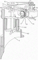
Fig. 1 is a schematic perspective view of the present invention.
Fig. 2 is a perspective sectional view of the present invention.
Fig. 3 is a schematic perspective view of the absorbing mechanism of the present invention.
Fig. 4 is a schematic perspective view of an erasing mechanism according to the present invention.
Fig. 5 is a schematic perspective view of the swing mechanism of the present invention.
Fig. 6 is an enlarged schematic perspective view of the invention at a.
Fig. 7 is a schematic perspective view of the extrusion mechanism of the present invention.
Fig. 8 is a cross-sectional view of the pressing mechanism of the present invention.
Fig. 9 is a schematic perspective view of the collecting mechanism of the present invention.
Fig. 10 is a schematic perspective view of the heating mechanism of the present invention.
Wherein the figures include the following reference numerals: 1. the device comprises a supporting base, 2, a dryer, 3, a door, 4, an exhaust pipe, 5, an absorption mechanism, 51, an air suction bin, 52, a centrifugal fan, 53, a double-shaft motor, 6, an erasing mechanism, 61, a transmission component, 62, a supporting frame, 63, a rotating frame, 64, a sponge cylinder, 7, a swinging mechanism, 71, a stirring frame, 72, a pressure rod, 73, a flow deflector, 74, a torsion spring, 8, an extrusion mechanism, 81, a rotating shaft, 82, an extrusion cylinder, 83, a fixed disc, 84, a water guide pipe, 9, a collecting mechanism, 91, a water collecting tank, 92, a water storage box, 93, a handle, 10, a heating mechanism, 101, a supporting block, 102, a threaded rod, 103 and a heating sheet.
Detailed Description
It is to be noted that, in the case of the different described embodiments, identical components are provided with the same reference numerals or the same component names, wherein the disclosure contained in the entire description can be transferred to identical components having the same reference numerals or the same component names in a meaningful manner. The positional references selected in the description, for example, upper, lower, lateral, etc., also refer to the directly described and illustrated figures and are to be read into the new position when the position is changed.
Example 1
The utility model provides a dehydrating unit for organic pigment preparation, as shown in figure 1 and figure 2, including supporting base 1, drying-machine 2, door 3, blast pipe 4, absorbing mechanism 5 and erasing mechanism 6, drying-machine 2 is installed at supporting base 1 top, and the 3 rotary type of door is connected in drying-machine 2 front sides, and 4 rigid couplings of blast pipe are in the upper left side of drying-machine 2, and blast pipe 4 and drying-machine 2 UNICOM, 4 upper portions of blast pipe are equipped with absorbing mechanism 5, are equipped with in the blast pipe 4 and erase mechanism 6.
As shown in fig. 1 and 3, the absorbing mechanism 5 includes an air suction chamber 51, a centrifugal fan 52 and a dual-shaft motor 53, the air suction chamber 51 is fixedly connected to the upper portion of the exhaust pipe 4, the air suction chamber 51 is communicated with the exhaust pipe 4, the centrifugal fan 52 is installed on the right side of the air suction chamber 51, the air suction chamber 51 is communicated with the centrifugal fan 52, the dual-shaft motor 53 is installed on the upper portion of the centrifugal fan 52, and an output shaft at the lower portion of the dual-shaft motor 53 is connected to a main shaft of the centrifugal fan 52.
As shown in fig. 1, fig. 2 and fig. 4, the erasing mechanism 6 includes a transmission assembly 61, two support frames 62, a rotating frame 63 and a sponge cylinder 64, the number of the support frames 62 is two, the two support frames 62 are respectively welded on the upper and lower sides of the inner wall of the exhaust pipe 4, the rotating frame 63 is rotatably connected between the two support frames 62, the transmission assembly 61 is wound on the output shafts of the upper part of the rotating frame 63 and the upper part of the double-shaft motor 53, the transmission assembly 61 is composed of two belt pulleys and a flat belt, the two belt pulleys are respectively connected on the output shafts of the upper part of the rotating frame 63 and the upper part of the double-shaft motor 53, the flat belt is wound on the two belt pulleys, the number of the sponge cylinders 64 is three, the three sponge cylinders 64 are circumferentially and uniformly and rotatably connected on the rotating frame 63, and the sponge cylinders 64 are all in contact with the inner wall of the exhaust pipe 4.
When organic pigment needs to be dehumidified, people firstly rotate to open the door 3, and place organic pigment in the dryer 2, then rotate to close the door 3, then start the dual-shaft motor 53, make the dual-shaft motor 53 start to operate, the output shaft on the upper portion of the dual-shaft motor 53 rotates to drive the rotating frame 63 to rotate through the transmission component 61, thereby drive the sponge cylinder 64 to rotate tightly against the inner wall of the exhaust pipe 4, then start the dryer 2, the dryer 2 operates to dry and dehumidify organic pigment, high-temperature steam generated by organic pigment in the drying process enters the exhaust pipe 4 from the dryer 2, because the steam temperature is high, make the internal temperature of the exhaust pipe 4 far higher than the external temperature, the steam is easily condensed on the inner wall of the exhaust pipe 4, at the moment, the sponge cylinder 64 tightly contacts the inner wall of the exhaust pipe 4 to rotate to absorb and erase the steam on the inner wall of the exhaust pipe 4, thereby avoiding steam from flowing into the dryer 2 along the exhaust pipe 4 to bring pollution to the organic pigment, and being beneficial to guarantee the quality of organic pigment, the dual-shaft motor 53 operates to rotate the output shaft of the lower portion of the dual-shaft motor 53, then, thereby further enabling the centrifugal fan 52 to be beneficial to prevent the centrifugal fan 52 from entering the centrifugal fan 52 to further remove the organic pigment after the centrifugal fan 52 and further removing the organic pigment, thereby further removing the organic pigment from the centrifugal fan 52, and further drying process, thereby further drying process, the centrifugal fan 52.
Example 2
On the basis of embodiment 1, as shown in fig. 1, 5 and 6, the air suction device further includes a swing mechanism 7, the swing mechanism 7 includes a toggle frame 71, a pressure lever 72, a flow deflector 73 and a torsion spring 74, the toggle frame 71 is welded on the upper portion of the rotating frame 63, the upper and lower portions of the inner side of the air suction bin 51 are symmetrically and rotatably connected with the flow deflector 73, the number of the torsion springs 74 is two, the two torsion springs 74 are respectively wound on the upper and lower portions of the flow deflector 73, the front and rear ends of the torsion spring 74 are respectively connected with the flow deflector 73 and the air bin 51, the pressure lever 72 is rotatably connected between the two flow deflectors 73, the pressure lever 72 is located in front of the air suction bin 51, and the toggle frame 71 rotates to downwardly extrude the pressure lever 72.
The swivel mount 63 rotates and drives the stirring frame 71 to rotate, when stirring the frame 71 and rotate to contacting with depression bar 72, stir frame 71 and extrude depression bar 72 downwards, make depression bar 72 downstream, thereby drive water conservancy diversion piece 73 upwards and rotate, torsion spring 74 takes place to twist reverse deformation this moment, when stirring frame 71 and rotate and break away from depression bar 72, torsion spring 74 resets and makes water conservancy diversion piece 73 rotate downwards, through the up-and-down rotation of water conservancy diversion piece 73, can carry out the water conservancy diversion to the steam that suction chamber 51 was inhaled, thereby can the multi-angle with steam suction chamber 51, can enlarge the scope of inhaling steam, do benefit to the efficiency that improves exhaust steam.
As shown in fig. 1, fig. 7 and fig. 8, the device further comprises an extruding mechanism 8, the extruding mechanism 8 comprises a rotating shaft 81, an extruding container 82, a fixed disk 83 and a water guide pipe 84, the rotating shaft 81 is rotatably connected to the right part of the exhaust pipe 4, the extruding container 82 is fixedly connected to the rotating shaft 81, the extruding container 82 is provided with a water inlet, a cavity is formed inside the extruding container 82, the sponge container 64 can be in contact with the extruding container 82 in a rotating mode, the fixed disk 83 is fixedly connected to the lower side of the inner wall of the extruding container 82, the water guide pipe 84 is fixedly connected to the bottom of the fixed disk 83, and the water guide pipe 84 is communicated with the extruding container 82.
As shown in fig. 2 and 9, the exhaust pipe cleaner further comprises a collecting mechanism 9, the collecting mechanism 9 comprises a water collecting tank 91, a water storage box 92 and a handle 93, the water collecting tank 91 is fixedly connected to the inner side of the exhaust pipe 4, the water collecting tank 91 is completely attached to the inner wall of the exhaust pipe 4, the water collecting tank 91 is located below the supporting frame 62 at the lower portion, the water storage box 92 is slidably connected into the exhaust pipe 4, the water storage box 92 is located below the water collecting tank 91, the water storage box 92 is communicated with the water collecting tank 91, and the handle 93 is welded to the left side of the water storage box 92.
When 4 inner wall steam of blast pipe is too much to condense into the drop of water, under the action of gravity of drop of water, the drop of water is along 4 inner wall landing of blast pipe to water catch bowl 91 in, the drop of water gets into water storage box 92 by water catch bowl 91 afterwards, thereby can collect the drop of water, avoid the drop of water to get into 2 organic pigments of polluting of drying-machine, do benefit to the quality of further assurance organic pigment, when organic pigment dehumidification is accomplished, outside pulling handle 93, thereby pull out water storage box 92, handle the water in the water storage box 92 afterwards, later put back water storage box 92, be convenient for use next time.
As shown in fig. 1 and 10, the exhaust pipe heating device further includes a heating mechanism 10, the heating mechanism 10 includes a supporting block 101, a threaded rod 102 and a heating plate 103, the supporting block 101 is welded on the outer wall of the exhaust pipe 4, the threaded rod 102 is rotatably connected to the supporting block 101, the heating plate 103 is slidably connected to the outer wall of the exhaust pipe 4, and the heating plate 103 is threadedly connected to the threaded rod 102.
Because high-temperature steam gets into blast pipe 4, make the inside temperature of blast pipe 4 far above external temperature, lead to the steam in blast pipe 4 to condense easily, in order to avoid the steam in blast pipe 4 to condense into the drop of water and fall into drying-machine 2 and pollute organic pigment, need in time to adjust the outside temperature of blast pipe 4, make the inside and outside temperature of blast pipe 4 tend to unanimity, when needing to adjust the outside temperature of blast pipe 4, connect heating plate 103 with the power, make heating plate 103 function, heating plate 103 function produces heat and heats the blast pipe 4 outer wall afterwards, and make the inside and outside temperature of blast pipe 4 tend to unanimity, thereby can avoid steam to condense and flow into drying-machine 2 and pollute organic pigment, do benefit to further guarantee the quality of organic pigment, then rotate threaded rod 102, threaded rod 102 rotates and drives heating plate 103 up-and-down motion, thereby can heat the outer wall of blast pipe 4 by a large scale, do benefit to improve blast pipe 4 heating efficiency, when need not adjust the inside and outside temperature of blast pipe 4, loosen threaded rod 102, and the disconnection of heating plate 103 with the power can.
It should be understood by those skilled in the art that the above embodiments do not limit the present invention in any way, and all technical solutions obtained by using equivalent alternatives or equivalent variations fall within the scope of the present invention.
Claims (8)
1. The utility model provides a dehydrating unit for organic pigment preparation, is including supporting base (1), drying-machine (2), door (3) and blast pipe (4), supports base (1) top and installs drying-machine (2), and drying-machine (2) front side rotation type is connected with door (3), and blast pipe (4) are installed to the upper left side of drying-machine (2), and blast pipe (4) and drying-machine (2) UNICOM, its characterized in that: the device is characterized by further comprising an absorption mechanism (5) and an erasing mechanism (6), wherein the absorption mechanism (5) used for rapidly absorbing water vapor in the exhaust pipe (4) is arranged on the upper portion of the exhaust pipe (4), and the erasing mechanism (6) used for erasing the water vapor on the inner wall of the exhaust pipe (4) is arranged in the exhaust pipe (4).
2. The dehumidifying apparatus for organic pigment preparation according to claim 1, wherein: the absorption mechanism (5) comprises an air suction bin (51), a centrifugal fan (52) and a double-shaft motor (53), the air suction bin (51) is installed on the upper portion of the exhaust pipe (4), the air suction bin (51) is communicated with the exhaust pipe (4), the centrifugal fan (52) is installed on the right side of the air suction bin (51), the air suction bin (51) is communicated with the centrifugal fan (52), the double-shaft motor (53) is installed on the upper portion of the centrifugal fan (52), and an output shaft of the lower portion of the double-shaft motor (53) is connected with a main shaft of the centrifugal fan (52).
3. The dehumidifying apparatus for organic pigment preparation according to claim 2, wherein: the erasing mechanism (6) comprises a transmission assembly (61), a support frame (62), a rotating frame (63) and a sponge cylinder (64), the support frame (62) is installed on the upper side and the lower side of the inner wall of the exhaust pipe (4), the rotating frame (63) is connected between the two support frames (62) in a rotating mode, the transmission assembly (61) is wound on output shafts on the upper portion of the rotating frame (63) and the upper portion of the double-shaft motor (53), the sponge cylinder (64) is connected on the rotating frame (63) in a circumferential uniform rotating mode, and the sponge cylinder (64) is in contact with the inner wall of the exhaust pipe (4).
4. The dehumidifying apparatus for organic pigment preparation according to claim 3, wherein: still including being used for the multi-angle to inhale swing mechanism (7) of inhaling storehouse (51) with steam, swing mechanism (7) are including stirring frame (71), depression bar (72), water conservancy diversion piece (73) and torque spring (74), swivel mount (63) upper portion is connected with stirs frame (71), the equal rotary type in both sides about inhaling storehouse (51) inboard is connected with water conservancy diversion piece (73), all around torque spring (74) on water conservancy diversion piece (73), torque spring (74) inside and outside both ends are equallyd divide and are connected with water conservancy diversion piece (73) and the storehouse (51) of breathing in, the rotary type is connected with depression bar (72) between two water conservancy diversion pieces (73), depression bar (72) are located and inhale storehouse (51) the place ahead, stir frame (71) and rotate downward extrusion depression bar (72).
5. The dehumidifying apparatus for organic pigment preparation according to claim 4, wherein: still including being used for extruding the extruding means (8) of the absorptive steam of sponge cylinder (64), extruding means (8) is including pivot (81), recipient (82), fixed disk (83) and aqueduct (84), blast pipe (4) right part rotary type is connected with pivot (81), install recipient (82) from taking the water inlet on pivot (81), the inside cavity that is of recipient (82), sponge cylinder (64) rotate extrusion recipient (82), recipient (82) inner wall downside is connected with fixed disk (83), aqueduct (84) are installed to fixed disk (83) bottom, aqueduct (84) and recipient (82) UNICOM.
6. The dehumidifying apparatus for organic pigment preparation according to claim 5, wherein: still including collection mechanism (9) that are used for collecting blast pipe (4) inner wall steam condensate to form the drop of water, collect mechanism (9) including water catch bowl (91) and water storage box (92), install water catch bowl (91) in blast pipe (4), water catch bowl (91) and blast pipe (4) inner wall laminate completely, water catch bowl (91) are located support frame (62) below of lower part, slidingtype is connected with water storage box (92) in blast pipe (4), water storage box (92) are located water catch bowl (91) below, water storage box (92) and water collection box (91) UNICOM.
7. The dehumidifying apparatus for organic pigment preparation according to claim 6, wherein: the exhaust pipe heating device is characterized by further comprising a heating mechanism (10) used for heating the outer wall of the exhaust pipe (4), wherein the heating mechanism (10) comprises a supporting block (101), a threaded rod (102) and a heating piece (103), the supporting block (101) is installed on the outer wall of the exhaust pipe (4), the threaded rod (102) is connected in the supporting block (101) in a rotating mode, the heating piece (103) is connected to the outer wall of the exhaust pipe (4) in a sliding mode, and the heating piece (103) is connected with the threaded rod (102) in a threaded mode.
8. The dehumidifying apparatus for organic pigment preparation according to claim 6, wherein: the water storage box further comprises a handle (93), and the handle (93) is installed on the left side of the water storage box (92).
Priority Applications (1)
| Application Number | Priority Date | Filing Date | Title |
|---|---|---|---|
| CN202211189234.6A CN115493369B (en) | 2022-09-28 | 2022-09-28 | Dehumidification device for organic pigment preparation |
Applications Claiming Priority (1)
| Application Number | Priority Date | Filing Date | Title |
|---|---|---|---|
| CN202211189234.6A CN115493369B (en) | 2022-09-28 | 2022-09-28 | Dehumidification device for organic pigment preparation |
Publications (2)
| Publication Number | Publication Date |
|---|---|
| CN115493369A true CN115493369A (en) | 2022-12-20 |
| CN115493369B CN115493369B (en) | 2024-04-12 |
Family
ID=84472650
Family Applications (1)
| Application Number | Title | Priority Date | Filing Date |
|---|---|---|---|
| CN202211189234.6A Active CN115493369B (en) | 2022-09-28 | 2022-09-28 | Dehumidification device for organic pigment preparation |
Country Status (1)
| Country | Link |
|---|---|
| CN (1) | CN115493369B (en) |
Cited By (1)
| Publication number | Priority date | Publication date | Assignee | Title |
|---|---|---|---|---|
| CN116761385A (en) * | 2023-05-17 | 2023-09-15 | 艺坤智慧水务集团有限公司 | Pump house data acquisition device |
Citations (5)
| Publication number | Priority date | Publication date | Assignee | Title |
|---|---|---|---|---|
| KR20100065421A (en) * | 2008-12-08 | 2010-06-17 | 한국마사회 | Racing road draining apparatus |
| CN108870885A (en) * | 2018-08-07 | 2018-11-23 | 佛山市广协环保科技有限公司 | A kind of highly effective drying case |
| CN212362784U (en) * | 2020-01-03 | 2021-01-15 | 杭州美美科技有限公司 | System for draining and drying residual water in tank body of endoscope cleaning and disinfecting machine |
| CN216092987U (en) * | 2021-09-06 | 2022-03-22 | 松菱重工(溧阳)有限公司 | Low-energy-consumption gas-liquid separation type air cooler |
| CN217257551U (en) * | 2021-12-03 | 2022-08-23 | 深圳市华疆盛环境产业发展有限公司 | Plastic dehumidifying dryer |
-
2022
- 2022-09-28 CN CN202211189234.6A patent/CN115493369B/en active Active
Patent Citations (5)
| Publication number | Priority date | Publication date | Assignee | Title |
|---|---|---|---|---|
| KR20100065421A (en) * | 2008-12-08 | 2010-06-17 | 한국마사회 | Racing road draining apparatus |
| CN108870885A (en) * | 2018-08-07 | 2018-11-23 | 佛山市广协环保科技有限公司 | A kind of highly effective drying case |
| CN212362784U (en) * | 2020-01-03 | 2021-01-15 | 杭州美美科技有限公司 | System for draining and drying residual water in tank body of endoscope cleaning and disinfecting machine |
| CN216092987U (en) * | 2021-09-06 | 2022-03-22 | 松菱重工(溧阳)有限公司 | Low-energy-consumption gas-liquid separation type air cooler |
| CN217257551U (en) * | 2021-12-03 | 2022-08-23 | 深圳市华疆盛环境产业发展有限公司 | Plastic dehumidifying dryer |
Cited By (2)
| Publication number | Priority date | Publication date | Assignee | Title |
|---|---|---|---|---|
| CN116761385A (en) * | 2023-05-17 | 2023-09-15 | 艺坤智慧水务集团有限公司 | Pump house data acquisition device |
| CN116761385B (en) * | 2023-05-17 | 2023-12-19 | 艺坤智慧水务集团有限公司 | Pump house data acquisition device |
Also Published As
| Publication number | Publication date |
|---|---|
| CN115493369B (en) | 2024-04-12 |
Similar Documents
| Publication | Publication Date | Title |
|---|---|---|
| CN115493369A (en) | Dehumidification device for organic pigment preparation | |
| CN116987868A (en) | Hot air circulation equipment for aluminum profile aging furnace | |
| CN209910309U (en) | Air energy dryer with filtering and dust removing functions | |
| CN114719564A (en) | High-efficient drying equipment of honeysuckle preparation | |
| CN208312942U (en) | Rotary drier is used in a kind of manufacture of chemical industry | |
| CN116358262B (en) | Vertical stirring vacuum dryer | |
| CN110260632A (en) | Drying device is used in a kind of preparation of flame-resistant plastic-wood composite materials | |
| CN214065451U (en) | Vacuum rake dryer | |
| CN215536654U (en) | Automatic ejection of compact capsule machine | |
| CN215040240U (en) | Novel plastic film blowing machine | |
| CN211120458U (en) | Potassium monopersulfate bag-type dust removal dryer | |
| CN116222181B (en) | Honeycomb formula SCR denitration catalyst stoving mechanism | |
| CN219283840U (en) | Heat circulation system of spin flash dryer | |
| CN217465213U (en) | Drying device for catalyst production | |
| CN220507638U (en) | Steam heat exchange rotary dryer | |
| CN211290854U (en) | Particle drying device | |
| CN113390249B (en) | Equipment convenient to maintain for new material heat treatment | |
| CN218034195U (en) | Paddle dryer | |
| CN219572538U (en) | Rotary drying device | |
| CN109341208A (en) | The circulator of tea machinery | |
| CN214665586U (en) | Box type fluidized drying machine | |
| CN219913792U (en) | Pharmaceutical chemical raw material drying device with self-cleaning function | |
| CN220360714U (en) | Microwave drying device is used in barium sulfate production | |
| CN216072129U (en) | Pneumatic conveying device with pressurization boosting mechanism | |
| CN220269951U (en) | Chemical product production drying cabinet |
Legal Events
| Date | Code | Title | Description |
|---|---|---|---|
| PB01 | Publication | ||
| PB01 | Publication | ||
| SE01 | Entry into force of request for substantive examination | ||
| SE01 | Entry into force of request for substantive examination | ||
| GR01 | Patent grant | ||
| GR01 | Patent grant |