CN115489027A - Vertical shaft vibration stirrer for fluidized solidified soil and stirring method - Google Patents
Vertical shaft vibration stirrer for fluidized solidified soil and stirring method Download PDFInfo
- Publication number
- CN115489027A CN115489027A CN202211208068.XA CN202211208068A CN115489027A CN 115489027 A CN115489027 A CN 115489027A CN 202211208068 A CN202211208068 A CN 202211208068A CN 115489027 A CN115489027 A CN 115489027A
- Authority
- CN
- China
- Prior art keywords
- stirring
- vibration
- pot
- soil
- solidified soil
- Prior art date
- Legal status (The legal status is an assumption and is not a legal conclusion. Google has not performed a legal analysis and makes no representation as to the accuracy of the status listed.)
- Pending
Links
Images


Classifications
-
- B—PERFORMING OPERATIONS; TRANSPORTING
- B28—WORKING CEMENT, CLAY, OR STONE
- B28C—PREPARING CLAY; PRODUCING MIXTURES CONTAINING CLAY OR CEMENTITIOUS MATERIAL, e.g. PLASTER
- B28C5/00—Apparatus or methods for producing mixtures of cement with other substances, e.g. slurries, mortars, porous or fibrous compositions
- B28C5/08—Apparatus or methods for producing mixtures of cement with other substances, e.g. slurries, mortars, porous or fibrous compositions using driven mechanical means affecting the mixing
- B28C5/0806—Details; Accessories
- B28C5/0831—Drives or drive systems, e.g. toothed racks, winches
-
- B—PERFORMING OPERATIONS; TRANSPORTING
- B28—WORKING CEMENT, CLAY, OR STONE
- B28C—PREPARING CLAY; PRODUCING MIXTURES CONTAINING CLAY OR CEMENTITIOUS MATERIAL, e.g. PLASTER
- B28C5/00—Apparatus or methods for producing mixtures of cement with other substances, e.g. slurries, mortars, porous or fibrous compositions
- B28C5/08—Apparatus or methods for producing mixtures of cement with other substances, e.g. slurries, mortars, porous or fibrous compositions using driven mechanical means affecting the mixing
- B28C5/0862—Adaptations of mixing containers therefor, e.g. use of material, coatings
-
- B—PERFORMING OPERATIONS; TRANSPORTING
- B28—WORKING CEMENT, CLAY, OR STONE
- B28C—PREPARING CLAY; PRODUCING MIXTURES CONTAINING CLAY OR CEMENTITIOUS MATERIAL, e.g. PLASTER
- B28C5/00—Apparatus or methods for producing mixtures of cement with other substances, e.g. slurries, mortars, porous or fibrous compositions
- B28C5/08—Apparatus or methods for producing mixtures of cement with other substances, e.g. slurries, mortars, porous or fibrous compositions using driven mechanical means affecting the mixing
- B28C5/18—Mixing in containers to which motion is imparted to effect the mixing
- B28C5/26—Mixing in containers to which motion is imparted to effect the mixing rotating about a vertical or steeply inclined axis during the mixing, e.g. comprising a flat bottomplate rotating about a vertical axis, co-operating with blades or stirrers
- B28C5/32—Mixing in containers to which motion is imparted to effect the mixing rotating about a vertical or steeply inclined axis during the mixing, e.g. comprising a flat bottomplate rotating about a vertical axis, co-operating with blades or stirrers with driven stirrers
-
- B—PERFORMING OPERATIONS; TRANSPORTING
- B28—WORKING CEMENT, CLAY, OR STONE
- B28C—PREPARING CLAY; PRODUCING MIXTURES CONTAINING CLAY OR CEMENTITIOUS MATERIAL, e.g. PLASTER
- B28C5/00—Apparatus or methods for producing mixtures of cement with other substances, e.g. slurries, mortars, porous or fibrous compositions
- B28C5/48—Apparatus or methods for producing mixtures of cement with other substances, e.g. slurries, mortars, porous or fibrous compositions wherein the mixing is effected by vibrations
-
- B—PERFORMING OPERATIONS; TRANSPORTING
- B28—WORKING CEMENT, CLAY, OR STONE
- B28C—PREPARING CLAY; PRODUCING MIXTURES CONTAINING CLAY OR CEMENTITIOUS MATERIAL, e.g. PLASTER
- B28C7/00—Controlling the operation of apparatus for producing mixtures of clay or cement with other substances; Supplying or proportioning the ingredients for mixing clay or cement with other substances; Discharging the mixture
- B28C7/04—Supplying or proportioning the ingredients
- B28C7/12—Supplying or proportioning liquid ingredients
-
- Y—GENERAL TAGGING OF NEW TECHNOLOGICAL DEVELOPMENTS; GENERAL TAGGING OF CROSS-SECTIONAL TECHNOLOGIES SPANNING OVER SEVERAL SECTIONS OF THE IPC; TECHNICAL SUBJECTS COVERED BY FORMER USPC CROSS-REFERENCE ART COLLECTIONS [XRACs] AND DIGESTS
- Y02—TECHNOLOGIES OR APPLICATIONS FOR MITIGATION OR ADAPTATION AGAINST CLIMATE CHANGE
- Y02P—CLIMATE CHANGE MITIGATION TECHNOLOGIES IN THE PRODUCTION OR PROCESSING OF GOODS
- Y02P70/00—Climate change mitigation technologies in the production process for final industrial or consumer products
- Y02P70/10—Greenhouse gas [GHG] capture, material saving, heat recovery or other energy efficient measures, e.g. motor control, characterised by manufacturing processes, e.g. for rolling metal or metal working
Abstract
The invention relates to a fluidized solidified soil vertical shaft vibration stirrer and a stirring method. During stirring, the materials such as soil, water, curing agent and the like are conveyed into a stirring pot at different times according to a certain proportion for vibration stirring, and the materials are discharged from a discharge port after being mixed by the dual functions of forced stirring and vibration strengthening, so that the stirred fluid state curing soil is obtained. The stirring function of the fluidized solidified soil stirrer disclosed by the invention is more thorough, the vibration strengthening effect is fully covered, various fluidized solidified soils can be mixed, and the stirring stirrer has the advantages of short stirring time, good mixing effect and the like. The stirred fluidized solidified soil has stable performance, high strength and good durability, the dosage of the solidifying agent material can be reduced under the same condition, and the use cost is saved.
Description
Technical Field
The invention relates to a solidified soil stirrer and a stirring method, in particular to a fluidized solidified soil vertical shaft vibration stirrer and a stirring method.
Background
The solidified soil is a soil body material with certain strength obtained by solidifying soil particles by adopting materials such as cement or other solidifying agents. The fluid solidified soil is premixed solidified soil which has certain fluidity and can be used for pouring construction, has good construction convenience due to larger fluidity, can be constructed by adopting pumping and other modes, is suitable for backfilling and pouring of various foundation pits, foundation troughs and mine pits, and can be widely used in the field of reinforcing treatment of road foundations, building foundations and the like. The formed solidified soil has high strength, controllable quality and lower cost.
The fluid solidified soil is mainly composed of crushed and screened soil, cement or other solidifying agents, water and additives, and is a multi-component mixed material similar to cement concrete, so that the materials with stable performance need to be mixed and stirred. However, fluid-state solidified soil is different from cement concrete, and cement or other curing agent materials in the solidified soil play the most important role due to low proportion. In addition, the main material soil in the solidified soil has higher viscosity, particularly soil with higher clay content, soil and cement or other curing agents are easy to stick on the side wall or the stirring blade in the stirring process, so that the mixing is not uniform, aggregate particles with large particle size are not contained in the solidified soil, and the self-dropping effect in the stirring is obviously reduced. The above factors all have adverse effects on the uniform mixing of the solidified soil in the stirring process, so that the fluid solidified soil is more difficult to be uniformly stirred compared with cement concrete, if the stirring is not uniform, the added cement or other curing agent particles or soil particles can be gathered together, the workability and the hardening strength of the fluid solidified soil are further improved, the required solidification effect cannot be exerted, and the performance of the fluid solidified soil is restricted. The method for manufacturing solidified soil provided in patent CN113211630A "method for manufacturing solidified soil" may improve uniformity, but the whole process is complicated, the actual operation is easy to cause problems, the stirring time is greatly prolonged, and the method is not completely suitable for engineering. When the double-horizontal-shaft mixer and the method which are the same as those of cement concrete are adopted, the mixing efficiency of the mixer is low, the mixing time is prolonged, the energy consumption is increased, the on-site production efficiency is influenced, and the improvement effect is limited. Because the double-horizontal-shaft stirrer is more suitable for stirring concrete and other mixtures containing aggregates with larger particle sizes, the composition particles in the fluid solidified soil are smaller, the horizontal-shaft stirrer is not suitable for horizontal-shaft stirring, and the double-horizontal-shaft stirrer is more suitable for a vertical-shaft stirring mode. The problem that special stirring equipment and a corresponding stirring method are still lacked in the application process of the current fluidized solidified soil is solved.
The vibration stirring technology is characterized in that the vibration effect is increased while the materials are stirred, so that the materials are in a flutter state after having certain vibration frequency and amplitude, the viscous connection among the material particles can be broken, the internal friction force among the materials is reduced, the particles are changed into an evenly distributed state from a caking state, and the uniform dispersion of the materials is facilitated. In order to reduce or even eliminate the problem of poor stirring uniformity of the fluid solidified soil, the method can further improve the mixing uniformity of the fluid solidified soil by increasing vibration in the stirring process.
In order to uniformly stir soil and a curing agent in a short time, a vertical shaft vibration stirrer capable of stirring fluid-state curing soil on site and a corresponding stirring method are designed, fluid-state curing soil materials with different compositions can be rapidly and uniformly stirred to meet different construction requirements, the construction effect along with stirring and filling is realized, and the construction progress is accelerated.
Disclosure of Invention
The invention aims to provide a vertical shaft vibration stirrer and a stirring method which can uniformly stir fluid state solidified soil in a short time, aiming at solving the problem that the fluid state solidified soil is difficult to stir uniformly on site at present.
The invention discloses a fluidized solidified soil vertical shaft vibration stirrer which comprises a stirring pot, a stirring motor, a stirring shaft, a stirring paddle, a vibration driving motor, a central vibrator, an attached vibrator and a damping support platform, wherein the stirring shaft is arranged on the stirring pot; the stirring pot is of a one-piece double-cylinder structure; the number of the stirring motors, the stirring shafts and the stirring paddles is two; the mixing motor is a variable frequency motor, the two mixing motors are respectively and fixedly arranged above the circle center positions of the two cylinders at the top of the mixing pot, the output shafts of the two mixing motors are respectively and fixedly provided with a mixing shaft, the two stirring shafts respectively penetrate through bearings at the circle centers of the two cylinders at the top of the stirring pot and extend into the stirring pot, the rotation directions of the two stirring shafts are opposite, and stirring paddles are fixedly arranged on the two stirring shafts; the vibration driving motor is fixedly arranged above the central position of the double cylinders at the top of the stirring pot, an output shaft of the vibration driving motor is connected with the central vibrator, and the central vibrator penetrates through the central position of the double cylinders at the top of the stirring pot and extends into the stirring pot; the attached vibrator is arranged on the outer side wall of the stirring pot; the damping supporting platform is fixedly arranged at the bottom of the stirring pot; the top of the cylinder at one side of the stirring pot is provided with a material inlet, the bottom of the cylinder at the other side of the stirring pot is provided with a material outlet, and the material outlet is provided with a switch valve.
The rotation direction of the stirring shaft is opposite, the solidified soil slurry can form turbulent flow at the center of the double cylinders of the stirring pot under the driving of the stirring paddle on the stirring shaft in the stirring process, and the generated shearing force is favorable for further uniform mixing of the materials.
The stirring paddle is of a double helical ribbon screw structure, the double helical ribbon of the stirring paddle is in a spiral ascending trend along with the rotation direction of the stirring shaft, and the screw is in a spiral descending trend along with the rotation direction of the stirring shaft. In the stirring process, the flow state solidified soil slurry not only can carry out the circular motion on the horizontal direction under the drive of the ribbon and the screw rod of stirring rake, also can form the flow of upper and lower circulation at the stirring in-process, and the slurry of keeping away from the (mixing) shaft is lifted to the eminence by the ribbon, and the slurry that is close to the (mixing) shaft region then can be pressed to the bottom by the screw rod for the stirring is more abundant, and efficiency is higher.
The central vibrator is arranged between the two stirring shafts. The central vibrator can apply certain intensity vibration to the fluid solidified soil slurry around the central vibrator during stirring. Therefore, the cement or other curing agents and the soil are forced to be stirred continuously and simultaneously subjected to the vibration action of high frequency and are in a flutter state, so that the dispersion of powder and the soil is enhanced, and the mixing uniformity and stability of the cured soil are further improved.
The central vibrator is of a cylindrical structure and is divided into a transmission protection part and a vibration part, the transmission protection part is arranged at the upper part of the central vibrator, the transmission shaft is arranged in the central vibrator, the protection shell is arranged outside the central vibrator, and the vibration part is arranged at the lower part of the central vibrator. The transmission protection part mainly plays a role in fixing protection and power transmission, the outer diameter of the top end of the transmission protection part is larger than the diameter of a double-cylinder center through hole at the top of the stirring pot, the outer diameter of the rest part is consistent with that of the double-cylinder center through hole, the central vibrator is inserted into the double-cylinder center through hole of the stirring pot and then is large in outer diameter at the top end, the stirring pot can be prevented from falling into the stirring pot and is fixed with the top of the stirring pot, the rest part can penetrate through the double-cylinder center through hole of the stirring pot, the outer shell is thickened to form a protective shell to increase rigidity, the outer shell is prevented from being stressed and bent in the stirring process, and the power of the driving motor is transmitted to the vibration part through the inner transmission shaft. The vibration part adopts an eccentric working principle to generate vibration, and the vibration driving motor rotates at a high speed and drives the central vibrator to generate vibration with a certain frequency. The height of the upper end of the vibration part is flush with the height of the upper edge of the stirring paddle, and the lower end of the vibration part is close to the bottom of the stirring pot, so that the vibration strengthening effect is fully exerted.
The number of the attached vibrators is six, the number of the single-side cylinders of the stirring pot is three, the attached vibrators and the central vibrators are arranged in a cross shape in the horizontal direction, and the vertical installation position is an area below the middle of the outer side wall of the stirring pot. The installation of attached vibrator can reduce the adhesion volume of stirring in-process slurry at the agitated kettle inner wall on the one hand, reduce the waste of cement or other curing agent materials, on the other hand also can exert certain vibration to the regional flow state solidification soil slurry in agitated kettle edge, play the vibration reinforcing effect, compensatied the not enough problem of vibration region cover face of central vibrator, such design also makes central vibrator vibration intensity need not very greatly, changes the life of guaranteeing central vibrator and the reliability of mixer work.
The damping support platform comprises a connecting steel plate, a damping type spring damper, a bottom plate and a telescopic base; the connecting steel plate is fixedly connected with the bottom of the stirring pot, the four damping type spring shock absorbers are fixedly connected between the connecting steel plate and the bottom plate in a rectangular array mode, and four telescopic bases are installed at four corners of the lower surface of the bottom plate. The damping type spring shock absorber of the shock absorption supporting platform can eliminate most of vibration generated by the stirring machine, and influence on the ground foundation is reduced. The arrangement of the telescopic base can also ensure that the stirrer can be installed and fixed on uneven ground.
The vibrating and stirring method of fluid solidified soil includes the following steps:
1) Adding a certain mass of treated soil and mixing water into a stirring pot from a feed inlet of a stirrer;
2) Starting two stirring motors and a vibration driving motor at the top of the stirring pot, starting reverse rotation of the two stirring shafts, starting vibration of a central vibrator, and preparing soil and water into slurry after working for 1-5 minutes;
3) The two stirring motors and the vibration driving motor still continue to work, other materials such as curing agents are conveyed into the stirring pot in proportion, and meanwhile, the six attached vibrators are started to continue to vibrate and stir for 1-3 minutes to prepare fluid-state solidified soil;
4) And (3) keeping the stirring motor on one side of the discharge port to be started, stopping the stirring motor, the vibration driving motor and the six attached vibrators on the other side, opening a switch valve in the discharge port, starting discharging, starting the six attached vibrators for 5-20 seconds to shake off the adhered slurry when the discharging is about to be finished, stopping the stirring motor after the discharging is finished, and closing the switch valve.
The invention discloses a vertical shaft vibration stirrer for fluidized solidified soil, which adopts the design of a double-cylinder stirring pot, and a stirring device and a vibrating device are mutually independent. When the stirring device works, the stirring shaft and the stirring paddle do not participate in the vibration action, only the common static stirring action is applied to the mixed materials, and the central vibrator and the attached vibrator arranged on the outer side wall of the stirring pot apply the vibration action to the materials. The effective vibration area of the central vibrator is moderate, vibration energy is transmitted to the periphery of the central vibrator, the attached vibrator enables the mixture in the edge area of the stirring pot to obtain enough vibration energy, and the attached vibrator and the mixture can obtain ideal vibration mixing effect by combining the attached vibrator and the mixture. Meanwhile, the central vibrator does not need larger vibration intensity, and the vibration strengthening of the materials in the stirring pot can be realized according to the vibration intensity design of a common vibration machine, so that the service life and the working reliability of the stirring machine are easier to ensure. The fluid-state solidified soil obtained by the stirring method has stable performance, high strength and good durability, the consumption of the solidifying agent material can be reduced under the same condition, and the use cost is saved.
Drawings
In order to more clearly describe the technical scheme of the present invention, the drawings in the embodiments will be briefly described below, the drawings are only embodiments of the present invention, and for those skilled in the art, other drawings can be obtained according to the drawings without creative efforts.
FIG. 1 is a schematic front view of the vertical shaft vibratory blender of the present invention.
FIG. 2 is a top view of the vertical shaft vibratory blender of the present invention.
FIG. 3 is a side view of the vertical shaft vibratory blender of the present invention.
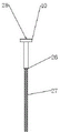
Fig. 4 is a schematic view of a central vibrator.
Description of reference numerals: 1-a stirring pot; no. 2-1 stirring motor; no. 3-2 stirring motor; 4-vibration driving motor; 5-a feed inlet; no. 6-1 stirring shaft; no. 7-2 stirring shaft; 8-1 bearing; 9-2 bearing; 10-a central vibrator; no. 11-1 double helical ribbon screw type stirring paddle; no. 12-2 double helical ribbon screw type stirring paddle; 13-1 attached vibrator; 14-2 attached vibrator; 15-a discharge hole; 16-switching the valve; 17-a shock-absorbing support platform; 18-connecting steel plates; 19-damped spring shock absorbers; 20-a base plate; 21-a telescopic base; 22-3 attached vibrator; no. 23-4 attachment vibrator; 24-5 attached vibrators; 25-6 attached vibrators; 26-a transmission protection part; 27-a vibrating portion; 28-drive shaft.
Detailed Description
The technical solution of the present invention will be further described in detail with reference to the accompanying drawings 1-4 and the specific embodiments.
Referring to fig. 1, the fluidized solidified soil vertical shaft vibration stirrer mainly comprises a stirring pot 1, a stirring motor 2, a vibration driving motor 4, a stirring shaft 6, a stirring shaft 7 of No. 1, a central vibrator 10, a double helical screw type stirring paddle 11, a double helical screw type stirring paddle 12 of No. 2, attached vibrators 13, 14, 22, 23, 24, 25 and a damping supporting platform 17.
The stirring pot 1 is of a one-piece type double-cylinder structure, two variable-frequency stirring motors 2 and 3 and a vibration driving motor 4 are fixedly installed at the top of the stirring pot 1, a stirring shaft 6 of the number 1 penetrates through a bearing 8 of the number 1 at the center of a cylinder at the top of the stirring pot 1 and is fixedly connected with an output shaft of the stirring motor 2 of the number 1, a double-helical-screw type stirring paddle 11 of the number 1 is fixed at the part of the stirring shaft 6 in the stirring pot 1, a stirring shaft 7 of the number 2 penetrates through a bearing 9 of the number 2 at the center of a cylinder at the top of the stirring pot 1 and is fixedly connected with an output shaft of the stirring motor 3 of the number 2, and a double-helical-screw type stirring paddle 12 of the number 2 is fixed at the part of the stirring shaft 7 in the stirring pot 1. The lower ends of the double helical ribbon screw type stirring paddles 11 and 12 are close to the bottom of the stirring pot 1, the diameter of the double helical ribbon screw type stirring paddles is slightly smaller than the diameter of a cylinder of the stirring pot 1, but the outer edge of the helical ribbon screw type stirring paddles cannot hit the vibration part of the central vibrator 10. Vibration driving motor 4 fixed mounting puts the top at the two drum central point at agitator kettle 1 top, vibration driving motor 4's output shaft is connected with central vibrator 10, central vibrator 10 passes the two drum center through holes at agitator kettle 1 top and extends to agitator kettle 1 inside, attached vibrator 13, 14, 22, 23, 24, 25 install at agitator kettle 1 lateral wall, shock attenuation supporting platform 17 fixed mounting is in agitator kettle 1 bottom, agitator kettle 1 one side drum top is provided with the feed inlet 5 of material, agitator kettle 1 another side drum bottom sets up discharge gate 15, discharge gate 15 department is provided with ooff valve 16.
No. 1 (mixing) shaft 6 is opposite with No. 2 (mixing) shaft 7's direction of rotation, and the solid soil thick liquids can form the vortex in the two drum central point of stirred tank 1 puts at the stirring in-process, and the shearing force that produces is favorable to the further misce bene of material. No. 1 stirring rake 11 and No. 2 stirring rake 12 are two helical ribbon screw structures, and the two helical ribbon of No. 1 stirring rake 11 is the spiral trend that rises along with the direction of rotation of No. 1 (mixing) shaft 6, and the screw rod is the spiral trend that descends along with the direction of rotation of No. 1 (mixing) shaft 6, and the two helical ribbon of No. 2 stirring rake 12 is the spiral trend that rises along with the direction of rotation of No. 2 (mixing) shaft 7, and the screw rod is the spiral trend that descends along with the direction of rotation of No. 2 (mixing) shaft 7. In the stirring process, the fluidized solidified soil slurry is driven by the ribbon and the screw of the stirring paddles 11 and 12 to perform circular motion in the horizontal direction, and form vertical circulation flow in the stirring process, the slurry far away from the stirring shafts 6 and 7 is lifted to a high position by the ribbon, and the slurry close to the stirring shafts 6 and 7 is pressed to the bottom by the screw, so that the stirring is more sufficient, and the efficiency is higher. A central vibrator 10 is provided intermediate the stirring shafts 6 and 7. The central vibrator 10 applies a certain intensity of vibration to the fluidized and solidified soil slurry around it while stirring. Therefore, the cement or other curing agents and the soil are forced to be stirred continuously and simultaneously subjected to the vibration action of high frequency and are in a flutter state, so that the dispersion of powder and the soil is enhanced, and the mixing uniformity and stability of the cured soil are further improved. The central vibrator 10 is a cylindrical structure and is divided into a transmission protection part 26 and a vibration part 27, the transmission protection part 26 is arranged at the upper part of the central vibrator, the transmission shaft 28 is arranged inside the transmission protection part 26, the protection shell is arranged outside the transmission protection part 26, and the vibration part 27 is arranged at the lower part of the central vibrator. The transmission protection part 26 mainly plays a role in fixing protection and power transmission, the outer diameter of the top end of the transmission protection part 26 is larger than the diameter of a double-cylinder center through hole at the top of the stirring pot 1, the outer diameters of the rest parts are consistent with the outer diameters of the rest parts, the central vibrator 10 is inserted into the double-cylinder center through hole of the stirring pot 1 and then is large in the outer diameter of the top end, the central vibrator can be prevented from falling into the stirring pot and being fixed with the top of the stirring pot 1, the rest parts can penetrate through the double-cylinder center through hole of the stirring pot 1, the outer shell is thickened to form a protective shell to increase rigidity, the protective shell is prevented from being stressed and bent in the stirring process, and the power of the vibration driving motor 4 is transmitted to the vibration part 27 through the transmission shaft 28 inside. The vibration part 27 generates vibration by adopting an eccentric working principle, and the vibration driving motor 4 rotates at a high speed and drives the vibration part 27 to generate vibration with a certain frequency. The height of the upper end of the vibration part 27 is flush with the height of the upper edges of the double-helical-band screw type stirring paddles 11 and 12, and the lower end of the vibration part is close to the bottom of the stirring pot 1, so that the vibration strengthening effect is fully exerted. Attached vibrators 13 and 14 are installed on the left and right sides of the double-cylinder agitating pan 1, and apply vibration to the fluidized and solidified soil slurry inside. The shock absorption supporting platform 17 comprises a connecting steel plate 18, a damping type spring shock absorber 19, a bottom plate 20 and a telescopic base 21; the connecting steel plate 18 is fixedly connected with the bottom of the stirring pot 1, the four damping type spring shock absorbers 19 are fixedly connected between the connecting steel plate 18 and the bottom plate 20 in a rectangular array mode, and four telescopic bases 21 are installed at four corners of the lower surface of the bottom plate 20. The damped spring damper 19 of the shock absorbing support platform 17 eliminates most of the vibrations generated by the blender and reduces the impact on the ground foundation. The telescopic base 21 can also be used for mounting and fixing the stirrer on uneven ground.
Referring to fig. 2, a stirring pot 1 of the fluidized solidified soil vertical shaft vibration stirrer is of a one-piece double-cylinder structure, a stirring motor 1 and a stirring motor 2 are respectively installed at the circle centers of two cylinders at the top of the stirring pot 1, a vibration driving motor 4 is installed at the center of the double cylinders, and the lower sides of the two cylinders are respectively connected with a stirring shaft 6 and a transmission shaft 28 of a central vibrator 10. The top of the cylinder at one side of the stirring pot 1 is provided with a material inlet 5 which can be connected with a material bin, a conveyor belt and a water tank which are provided with automatic metering and automatic control devices, so that the adding amount of materials can be conveniently controlled. Six attached vibrators 13, 14, 22, 23, 24 and 25 are fixedly arranged on the outer side walls of the double cylinders of the stirring pot 1, the number of the cylinders on one side of the stirring pot 1 is three, and the three attached vibrators and the central vibrator 10 are arranged in a cross shape in the horizontal direction. The installation of the attached vibrators 13, 14, 22, 23, 24 and 25 can reduce the adhesion amount of slurry on the inner wall of the mixing pot 1 in the mixing process and reduce the waste of cement or other curing agent materials, and can also apply certain vibration to the fluidized solidified soil slurry in the edge area of the mixing pot 1 to play a role in vibration reinforcement and make up the problem of insufficient coverage of the vibration area of the central vibrator 10, so that the design also ensures that the vibration strength of the central vibrator 10 does not need to be large, and the service life of the central vibrator 10 and the working reliability of the mixer are easier to ensure.
Referring to fig. 3, a discharge port 15 for the fluid state solidified soil is arranged at the bottom of the cylinder on the other side of the stirring pot 1, a switch valve 16 is arranged at the discharge port 15, and after stirring is finished, the switch valve 16 is opened, so that the material can be directly discharged or connected with a material tank of a pump machine to perform pumping construction of the fluid state solidified soil. The vertical mounting position of the attached vibrators 13, 14, 22, 23, 24, 25 in conjunction with fig. 1 is in the lower middle area of the outer side wall of the mixing pan 1, so that the vibration energy generated by the vibrators is maximally transferred and acted on the slurry at the edge of the mixing pan.
Referring to fig. 4, the center vibrator 10 is divided into a transmission protecting portion 26 and a vibrating portion 27, the transmission protecting portion 26 has a transmission shaft 28 therein to transmit power of the vibration driving motor 4 to the vibrating portion 27, and a thick protecting case is provided outside.
The stirring method of the fluid solidified soil comprises the following steps:
1) Adding a certain mass of treated soil and mixing water into the stirring pot 1 from a feed port 5 of the stirrer;
2) Starting a No. 1 stirring motor 2, a No. 2 stirring motor 3 and a vibration driving motor 4 at the top of a stirring pot 1, starting reverse rotation of a No. 1 stirring shaft 6 and a No. 2 stirring shaft 7, starting vibration of a central vibrator 10, and preparing soil and water into slurry after working for 1-5 minutes;
3) The stirring motor 2 No. 1, the stirring motor 3 No. 2 and the vibration driving motor 4 continue to work, curing agents and other materials are conveyed into the stirring pot 1 in proportion, meanwhile, six attached vibrators 13, 14, 22, 23, 24 and 25 are started, and the stirring is continued for 1-3 minutes to prepare fluid-state solidified soil;
4) The No. 2 stirring motor 3 on one side of the discharge port is kept on, the No. 1 stirring motor 2, the vibration driving motor 4 and the six attached vibrators 13, 14, 22, 23, 24 and 25 are turned off, the switch valve 16 in the discharge port 15 is opened, blanking is started, the six attached vibrators 13, 14, 22, 23, 24 and 25 are turned on for a short time for 5-20 seconds to shake off the adhered slurry when blanking is to be completed, the No. 2 stirring motor 3 is turned off after blanking is completed, and the switch valve 16 is turned off.
The electrical components present on the blender are connected to an external power source and a master controller, and the attached vibrator, the damped spring damper, the central vibrator, etc. are conventionally known devices.
The above-mentioned embodiments are only specific illustrations of the present invention, and the present invention is not limited by the illustrations, and all equivalent substitutions or changes according to the technical solutions and concepts of the present invention should be included in the scope of the present invention.
Claims (6)
1. A vertical shaft vibration stirrer for fluidized solidified soil comprises a stirring pot, a stirring motor, a stirring shaft, a stirring paddle, a vibration driving motor, a central vibrator, an attached vibrator and a damping support platform; the stirring pot is of a one-piece double-cylinder structure; the number of the stirring motors, the stirring shafts and the stirring paddles is two; the stirring motor is a variable frequency motor, the two stirring motors are respectively and fixedly arranged above the circle centers of the two cylinders at the top of the stirring pot, the output shafts of the two stirring motors are respectively and fixedly provided with stirring shafts, the two stirring shafts respectively penetrate through bearings at the circle centers of the two cylinders at the top of the stirring pot and extend into the stirring pot, the rotating directions of the two stirring shafts are opposite, and stirring paddles are respectively and fixedly arranged on the two stirring shafts; the vibration driving motor is fixedly arranged above the center position of the double cylinders at the top of the stirring pot, an output shaft of the vibration driving motor is connected with the central vibrator, and the central vibrator penetrates through the center position of the double cylinders at the top of the stirring pot and extends into the stirring pot; the attached vibrator is arranged on the outer side wall of the stirring pot; the damping supporting platform is fixedly arranged at the bottom of the stirring pot; the top of the cylinder at one side of the stirring pot is provided with a material inlet, the bottom of the cylinder at the other side of the stirring pot is provided with a material outlet, and the material outlet is provided with a switch valve.
2. The fluidized solidified soil vertical shaft vibration agitator of claim 1, wherein the agitator paddles are of a double helical ribbon screw type structure, the double helical ribbon of the agitator paddles having a helical upward trend along the rotation direction of the agitator shaft, and the screw having a helical downward trend along the rotation direction of the agitator shaft.
3. The fluidized solidified soil vertical shaft vibration agitator according to claim 1, wherein the central vibrator is arranged between the two stirring shafts, the central vibrator is of a cylindrical structure and is divided into a transmission protection part and a vibration part, the upper part of the central vibrator is the transmission protection part, the transmission shaft is arranged in the central vibrator, and the protection shell is arranged outside the central vibrator; the lower part of the central vibrator is a vibrating part.
4. The fluidized solidified soil vertical shaft vibration agitator of claim 1, wherein the number of the attached vibrators is six, the number of the single-side cylinders of the agitator kettle is three, the single-side cylinders of the agitator kettle are horizontally arranged in a cross shape with the central vibrator, and the vertical installation position is the lower region of the middle part of the outer side wall of the agitator kettle.
5. The fluidized solidified soil vertical shaft vibration mixer according to claim 1, wherein the shock absorbing support platform comprises a connecting steel plate, a damping spring shock absorber, a bottom plate and a telescopic base; the connecting steel plate is fixedly connected with the bottom of the stirring pot, the four damping type spring shock absorbers are fixedly connected between the connecting steel plate and the bottom plate in a rectangular array mode, and four telescopic bases are installed at four corners of the lower surface of the bottom plate.
6. A stirring method of a flow state solidified soil vibration stirrer is characterized by comprising the following steps:
1) Adding a certain mass of treated soil and mixing water into a stirring pot from a feed inlet of a stirrer;
2) Starting two stirring motors and a vibration driving motor at the top of the stirring pot, starting reverse rotation of the two stirring shafts, starting vibration of a central vibrator, and preparing soil and water into slurry after working for 1-5 minutes;
3) The two stirring motors and the vibration driving motor continue to work, other materials such as curing agents are conveyed into the stirring pot in proportion, and meanwhile, the six attached vibrators are started to continue to vibrate and stir for 1-3 minutes to prepare fluid-state solidified soil;
4) And (3) keeping the stirring motor on one side of the discharge port to be started, stopping the stirring motor, the vibration driving motor and the six attached vibrators on the other side, opening a switch valve in the discharge port, starting discharging, starting the six attached vibrators for 5-20 seconds to shake off the adhered slurry when the discharging is about to be finished, stopping the stirring motor after the discharging is finished, and closing the switch valve.
Applications Claiming Priority (2)
| Application Number | Priority Date | Filing Date | Title |
|---|---|---|---|
| CN2022105297470 | 2022-05-16 | ||
| CN202210529747 | 2022-05-16 |
Publications (1)
| Publication Number | Publication Date |
|---|---|
| CN115489027A true CN115489027A (en) | 2022-12-20 |
Family
ID=84473379
Family Applications (1)
| Application Number | Title | Priority Date | Filing Date |
|---|---|---|---|
| CN202211208068.XA Pending CN115489027A (en) | 2022-05-16 | 2022-09-30 | Vertical shaft vibration stirrer for fluidized solidified soil and stirring method |
Country Status (1)
| Country | Link |
|---|---|
| CN (1) | CN115489027A (en) |
Cited By (1)
| Publication number | Priority date | Publication date | Assignee | Title |
|---|---|---|---|---|
| CN116766399A (en) * | 2023-08-25 | 2023-09-19 | 西华大学 | Solidified soil integrated forming equipment |
-
2022
- 2022-09-30 CN CN202211208068.XA patent/CN115489027A/en active Pending
Cited By (2)
| Publication number | Priority date | Publication date | Assignee | Title |
|---|---|---|---|---|
| CN116766399A (en) * | 2023-08-25 | 2023-09-19 | 西华大学 | Solidified soil integrated forming equipment |
| CN116766399B (en) * | 2023-08-25 | 2023-11-17 | 西华大学 | Solidified soil integrated forming equipment |
Similar Documents
| Publication | Publication Date | Title |
|---|---|---|
| CN107116696A (en) | A kind of shaft vibration forced mixer | |
| CN115489027A (en) | Vertical shaft vibration stirrer for fluidized solidified soil and stirring method | |
| CN108748667A (en) | A kind of shimmy formula blender | |
| CN108608572A (en) | A kind of vibration type build concrete mixing plant | |
| CN205310527U (en) | Stabilized soil secondary agitating unit | |
| CN218365555U (en) | Flow state solidified soil vertical shaft vibration mixer | |
| CN211333915U (en) | Multi-functional earth mixer that mixes | |
| CN206937632U (en) | A kind of shaft vibration forced mixer | |
| CN108501219A (en) | A kind of blender for building with effect of vibration | |
| CN209491961U (en) | A kind of road and bridge construction concrete special agitating device | |
| CN2413888Y (en) | Reinforced agitator for concrete | |
| CN217862081U (en) | Movable fluidized solidified soil vertical shaft vibration stirrer | |
| CN218314381U (en) | Double-cylinder vibration stirrer for fluid solidified soil | |
| CN214687229U (en) | High-efficient agitating unit is used to pile foundation engineering | |
| CN213471683U (en) | Concrete mixing equipment | |
| CN217862039U (en) | Movable flow state solidified soil vibration stirrer | |
| CN212142438U (en) | Environment-friendly coating agitating unit | |
| CN105583954B (en) | A kind of continous way secondary mixer based on double frequency vibrating | |
| CN212421752U (en) | Concrete mixing device for civil engineering | |
| CN208759779U (en) | A kind of dual horizontal vibration blender | |
| CN211682871U (en) | Concrete mixer | |
| CN208148184U (en) | A kind of shimmy formula blender | |
| CN208097881U (en) | A kind of novel ribbon mixer being convenient to clean | |
| CN207480917U (en) | A kind of vertical vibrating blender with spiral vibrator | |
| CN207290509U (en) | A kind of efficient mortar mixer |
Legal Events
| Date | Code | Title | Description |
|---|---|---|---|
| PB01 | Publication | ||
| PB01 | Publication | ||
| SE01 | Entry into force of request for substantive examination | ||
| SE01 | Entry into force of request for substantive examination |