CN115458246A - Cable armouring machine - Google Patents
Cable armouring machine Download PDFInfo
- Publication number
- CN115458246A CN115458246A CN202211368351.9A CN202211368351A CN115458246A CN 115458246 A CN115458246 A CN 115458246A CN 202211368351 A CN202211368351 A CN 202211368351A CN 115458246 A CN115458246 A CN 115458246A
- Authority
- CN
- China
- Prior art keywords
- frame
- pressing
- driving
- belt
- cabling
- Prior art date
- Legal status (The legal status is an assumption and is not a legal conclusion. Google has not performed a legal analysis and makes no representation as to the accuracy of the status listed.)
- Granted
Links
- 230000007246 mechanism Effects 0.000 claims abstract description 95
- 238000003825 pressing Methods 0.000 claims abstract description 53
- 238000005096 rolling process Methods 0.000 claims abstract description 21
- 230000001360 synchronised effect Effects 0.000 claims description 10
- 230000033001 locomotion Effects 0.000 claims description 5
- RYGMFSIKBFXOCR-UHFFFAOYSA-N Copper Chemical compound [Cu] RYGMFSIKBFXOCR-UHFFFAOYSA-N 0.000 abstract description 71
- 229910052802 copper Inorganic materials 0.000 abstract description 71
- 239000010949 copper Substances 0.000 abstract description 71
- 229910000831 Steel Inorganic materials 0.000 abstract description 69
- 239000010959 steel Substances 0.000 abstract description 69
- 230000009471 action Effects 0.000 abstract description 11
- 238000005299 abrasion Methods 0.000 abstract description 3
- 230000002035 prolonged effect Effects 0.000 abstract description 3
- 238000000034 method Methods 0.000 description 18
- 230000008569 process Effects 0.000 description 9
- 230000000694 effects Effects 0.000 description 7
- 238000007790 scraping Methods 0.000 description 7
- 230000005540 biological transmission Effects 0.000 description 6
- 238000004804 winding Methods 0.000 description 5
- 238000005520 cutting process Methods 0.000 description 4
- 239000000463 material Substances 0.000 description 3
- 239000002184 metal Substances 0.000 description 2
- 229910052751 metal Inorganic materials 0.000 description 2
- 230000009286 beneficial effect Effects 0.000 description 1
- 230000008859 change Effects 0.000 description 1
- 238000005253 cladding Methods 0.000 description 1
- 239000011248 coating agent Substances 0.000 description 1
- 238000000576 coating method Methods 0.000 description 1
- 230000006835 compression Effects 0.000 description 1
- 238000007906 compression Methods 0.000 description 1
- 230000008602 contraction Effects 0.000 description 1
- 230000007547 defect Effects 0.000 description 1
- 230000003031 feeding effect Effects 0.000 description 1
- 230000006872 improvement Effects 0.000 description 1
- 238000010030 laminating Methods 0.000 description 1
- 238000004519 manufacturing process Methods 0.000 description 1
- 230000004048 modification Effects 0.000 description 1
- 238000012986 modification Methods 0.000 description 1
- 238000006467 substitution reaction Methods 0.000 description 1
Images


Classifications
-
- H—ELECTRICITY
- H01—ELECTRIC ELEMENTS
- H01B—CABLES; CONDUCTORS; INSULATORS; SELECTION OF MATERIALS FOR THEIR CONDUCTIVE, INSULATING OR DIELECTRIC PROPERTIES
- H01B13/00—Apparatus or processes specially adapted for manufacturing conductors or cables
- H01B13/22—Sheathing; Armouring; Screening; Applying other protective layers
- H01B13/26—Sheathing; Armouring; Screening; Applying other protective layers by winding, braiding or longitudinal lapping
- H01B13/2613—Sheathing; Armouring; Screening; Applying other protective layers by winding, braiding or longitudinal lapping by longitudinal lapping
Landscapes
- Engineering & Computer Science (AREA)
- Manufacturing & Machinery (AREA)
- Unwinding Webs (AREA)
- Unwinding Of Filamentary Materials (AREA)
Abstract
The invention relates to the technical field of cable armor layer wrapping equipment, in particular to a cabling armoring machine; the steel belt and the copper belt wrap Rao Yu at the outer wall of the cabling under the action of cabling tension through cabling rotation, so that the stress of the equipment is balanced, the excessive abrasion of the equipment is avoided, and the service life of the equipment is prolonged; the plasticity of the steel belt or the copper belt is improved, and the fitting degree of the steel belt or the copper belt on the cable forming surface is improved; the rolling mechanism comprises a base frame, an unreeling mechanism arranged on the base frame, a rolling mechanism and a driving wrapping mechanism, wherein the rolling mechanism comprises a sliding seat which can be slidably arranged on the base frame, a lifting seat which can be vertically slidably arranged on the sliding seat and a rolling assembly arranged on the lifting seat, a first driving mechanism which provides power for the sliding seat to slide is arranged on the base frame, a second driving mechanism which provides power for the lifting seat to slide vertically is arranged on the sliding seat, and the rolling assembly comprises a plurality of pressing supports which are uniformly distributed on the lifting seat and a pressing roller which is rotatably arranged at the bottom of the pressing supports.
Description
Technical Field
The invention relates to the technical field of cable armor layer wrapping equipment, in particular to a cabling armoring machine.
Background
As is well known, a cabling armouring machine is a device for covering and winding a cable armouring layer in the cable production process; publication (announcement) No. CN217386790U discloses an armored device for cable processing, which comprises an armored device body, wherein a wire inlet area is fixedly arranged on the left side of the upper end surface of the armored device body, a wire conduit is connected to the right side of the wire inlet area, a support is sleeved on the outer wall of the support, and fixed turntables are fixedly arranged on the front side and the back side of the support. The device has the advantages that through the cooperation between the armored device body, the feeding trolley, the lifting device and the supporting rod, the circumferential rotation of the first threaded rod in the lifting device is utilized, the limitation is combined with the limitation of the limiting speed, the lifting motion of the lifting block in the vertical direction of the outer wall of the first threaded rod is realized, the automatic feeding effect of the steel strip coil is achieved, the problem of manual feeding of the steel strip coil is effectively solved, the manual feeding mode is replaced by mechanical feeding, the workload of workers is reduced, the feeding progress of the steel strip coil is accelerated, and the armored processing working efficiency of cables is improved; in using the discovery, its mode through wrapping steel band or copper strips Rao Yu stranding outer wall realizes the winding of cable, at steel band or copper strips to the stranding outer wall around the in-process, the plasticity of steel band or copper strips is not good, steel band or copper strips remain further improvement at the laminating degree on stranding surface, the dress armour equipment rotation in-process of placing steel band or copper strips book, steel band and copper strips are installed in one side of dress armour equipment, dress armour equipment rotates the in-process and easily causes device eccentric rotation, cause the excessive wearing and tearing of equipment, influence the life of equipment.
Disclosure of Invention
Technical problem to be solved
Aiming at the defects of the prior art, the invention provides a method for coating Rao Yu cabled outer wall by a steel belt and a copper belt under the action of cabled tension through cabled rotation, so that the stress of equipment is balanced, the excessive abrasion of the equipment is avoided, and the service life of the equipment is prolonged; the cable-forming armoring machine improves the plasticity of the steel belt or the copper belt and the fitting degree of the steel belt or the copper belt on the surface of a formed cable.
(II) technical scheme
In order to achieve the purpose, the invention provides the following technical scheme: the rolling mechanism comprises a bottom frame, an unreeling mechanism, a rolling mechanism and a driving wrapping mechanism, wherein the unreeling mechanism, the rolling mechanism and the driving wrapping mechanism are arranged on the bottom frame; the driving wrapping mechanism comprises a mounting frame, four groups of pressing wheels rotatably mounted on the mounting frame and a third driving mechanism for providing power for the four groups of pressing wheels to synchronously rotate; the first driving mechanism and the second driving mechanism are preferably provided with a motor and a transmission belt, and the output end of the motor provides power with the corresponding sliding seat or lifting seat through the transmission belt; the first driving mechanism and the second driving mechanism can also adopt hydraulic cylinders, pneumatic cylinders or electric cylinders and the like, and the sliding seat and the lifting seat are driven by the hydraulic cylinders, the pneumatic cylinders or the electric cylinders; the third driving mechanism preferably comprises a motor and a plurality of synchronous belts, and the output end of the motor is in synchronous transmission connection with the four groups of pinch rollers through the plurality of synchronous belts.
Specifically, the unwinding mechanism comprises an unwinding frame, an unwinding roller rotatably arranged on the unwinding frame and a plurality of guide rollers rotatably arranged on the unwinding frame; the unwinding roller is wound with a steel belt or a copper belt, the steel belt or the copper belt bypasses a plurality of guide rollers, and the unwinding roller is driven to rotate through external tension, so that the steel belt or the copper belt is gradually unwound and fed from the unwinding roller.
The device comprises a base frame, a pressing shaft, a pressing assembly, a pressing motor, a pressing belt and a pressing mechanism, wherein the pressing shaft is arranged on the base frame; the top pressing assembly comprises a lifting frame and a top roller which is rotatably arranged on the lifting frame, and a fourth driving mechanism which provides power for the lifting frame to move up and down is arranged on the underframe; further, the top roller is positioned below the pressing shaft; the fourth driving mechanism can adopt a hydraulic cylinder, a pneumatic cylinder or an electric cylinder, the hydraulic cylinder, the pneumatic cylinder or the electric cylinder is fixedly arranged on the bottom frame, and the output end of the hydraulic cylinder, the pneumatic cylinder or the electric cylinder is fixedly connected with the lifting frame so as to provide power for the lifting frame to move up and down.
Specifically, the mounting frame comprises a fixed frame and two groups of symmetrically arranged rotating frames which are rotatably mounted on the fixed frame, a driving cylinder which provides power for the rotating frames to rotate is hinged on the underframe, and the two groups of pressing wheels are respectively rotatably mounted on the corresponding rotating frames; furthermore, one end of the driving cylinder is hinged with the underframe, and the other end of the driving cylinder is hinged with the corresponding rotating frame.
The tension adjusting mechanism comprises an eccentric frame and an adjusting roller, the eccentric frame is rotatably arranged on the underframe, the adjusting roller is rotatably arranged on the eccentric frame, and a fifth driving mechanism for providing power for the rotation of the eccentric frame is arranged on the underframe; the fifth driving mechanism is preferably a braking stepping motor, and can also adopt a braking servo motor; the fifth driving mechanism can also adopt a hydraulic cylinder, a gear and a rack, the gear is fixedly arranged on the eccentric frame, the hydraulic cylinder is fixedly arranged on the underframe, the rack is fixedly arranged at the output end of the hydraulic cylinder, and the gear is meshed with the rack.
Specifically, a leveling knife is arranged on the unreeling frame near one group of guide rollers, and the cutting edge of the leveling knife is arranged in parallel with the outer walls of the corresponding guide rollers; furthermore, the scraping knife is parallel to the central axis of the corresponding guide roller, and a gap is reserved between the scraping knife and the outer wall of the corresponding guide roller.
Specifically, the unreeling frame is slidably mounted on the underframe, and a sixth driving mechanism for providing power for the movement of the unreeling frame is mounted on the underframe; the sixth driving mechanism comprises a motor, a gear and a rack, the motor is fixedly mounted on the unwinding frame, a sliding rail is fixedly mounted on the bottom frame, the unwinding frame is slidably mounted on the sliding rail, the gear is fixedly mounted at the output end of the motor, the rack is fixedly mounted on the bottom frame, and the gear is meshed with the rack.
(III) advantageous effects
Compared with the prior art, the invention provides a cabling armouring machine, which has the following beneficial effects: the steel belt or the copper belt at the unwinding mechanism passes through the sliding groove, one end of the steel belt or the copper belt is wound at the outer wall of the cabling, the third driving mechanism acts, the synchronous belt drives the four groups of pressing wheels to rotate, the cabling rotates, meanwhile, the cabling is pulled and moved through the external winding traction equipment, the pressing wheels drive the cabling to rotate and simultaneously press the steel belt or the copper belt on the outer wall of the cabling, in the process, the second driving mechanism drives the lifting seat to move downwards, the pressing roller presses the steel belt or the copper belt into the sliding groove, meanwhile, the first driving mechanism drives the sliding seat to move transversely and leftwards, under the action of the pressing roller and the sliding groove, a rolling friction effect is formed on the steel belt or the copper belt passing through the rolling mechanism, under the rolling and friction effects, the local temperature of the copper belt or the steel belt rises to improve the metal plasticity of the steel belt or the copper belt, and in the process that the steel belt or the copper belt is wound on the outer wall of the cabling, under the action of the pressing roller, the steel belt or the copper belt is tightly attached to the outer wall of the cabling; through the cabling rotation, the steel belt and the copper belt wrap the Rao Yu cable outer wall under the action of the cabling tension, so that the stress of the equipment is balanced, the excessive abrasion of the equipment is avoided, and the service life of the equipment is prolonged; the plasticity of the steel belt or the copper belt is improved, and the fitting degree of the steel belt or the copper belt on the cable forming surface is improved.
Drawings
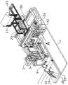
FIG. 1 is a schematic perspective view of the present invention;
FIG. 2 is a rear view of the present invention;
FIG. 3 is a schematic top view of the present invention;
FIG. 4 isbase:Sub>A schematic cross-sectional view taken along line A-A of FIG. 3 in accordance with the present invention;
FIG. 5 is an enlarged view of a portion of FIG. 1;
in the drawings, the reference numbers: 1. a chassis; 2. a sliding seat; 3. a lifting seat; 4. a first drive mechanism; 5. a second drive mechanism; 6. pressing and supporting; 7. a compression roller; 8. a chute; 9. a pinch roller; 10. a third drive mechanism; 11. unwinding the frame; 12. a guide roller; 13. a main shaft; 14. pressing the shaft; 15. a drive motor; 16. a lifting frame; 17. a top roll; 18. a fourth drive mechanism; 19. a fixed mount; 20. a rotating frame; 21. a drive cylinder; 22. an eccentric frame; 23. a leveling roller; 24. a fifth drive mechanism; 25. a scraping knife; 26. and a sixth drive mechanism.
Detailed Description
The technical solutions in the embodiments of the present invention will be clearly and completely described below with reference to the drawings in the embodiments of the present invention, and it is obvious that the described embodiments are only a part of the embodiments of the present invention, and not all of the embodiments. All other embodiments, which can be derived by a person skilled in the art from the embodiments given herein without making any creative effort, shall fall within the protection scope of the present invention.
Referring to fig. 1-5, the cable armouring machine of the invention comprises a chassis 1, an unreeling mechanism, a rolling mechanism and a driving wrapping mechanism, wherein the unreeling mechanism, the rolling mechanism and the driving wrapping mechanism are mounted on the chassis 1, the rolling mechanism comprises a sliding seat 2 which can be slidably mounted on the chassis 1, a lifting seat 3 which can be slidably mounted on the sliding seat 2 up and down, and a rolling component mounted on the lifting seat 3, a first driving mechanism 4 which provides power for the sliding of the sliding seat 2 is mounted on the chassis 1, a second driving mechanism 5 which provides power for the sliding of the lifting seat 3 up and down is mounted on the sliding seat 2, the rolling component comprises a plurality of pressure supports 6 which are uniformly distributed on the lifting seat 3 and a press roller 7 which can be rotatably mounted at the bottoms of the pressure supports 6, and a chute 8 is arranged on the sliding seat 2; the driving wrapping mechanism comprises a mounting frame, four groups of pressing wheels 9 which are rotatably arranged on the mounting frame and a third driving mechanism 10 which provides power for the synchronous rotation of the four groups of pressing wheels 9; the first driving mechanism 4 and the second driving mechanism 5 are preferably motors and transmission belts, and the output ends of the motors are powered by the transmission belts and the corresponding sliding seats 2 or lifting seats 3; the first driving mechanism 4 and the second driving mechanism 5 can also adopt a hydraulic cylinder, a pneumatic cylinder or an electric cylinder and the like, and the sliding seat 2 and the lifting seat 3 are driven by the hydraulic cylinder, the pneumatic cylinder or the electric cylinder; the third driving mechanism 10 preferably comprises a motor and a plurality of synchronous belts, and the output end of the motor is in synchronous transmission connection with the four groups of pinch rollers 9 through the plurality of synchronous belts.
Specifically, the unwinding mechanism comprises an unwinding frame 11, an unwinding roller rotatably mounted on the unwinding frame 11, and a plurality of guide rollers 12 rotatably mounted on the unwinding frame 11; the unwinding roller is wound with a steel belt or a copper belt, the steel belt or the copper belt bypasses the guide rollers 12, and the unwinding roller is driven to rotate by external tension, so that the steel belt or the copper belt is gradually unwound and fed from the unwinding roller; the steel belt or the copper belt bypasses each guide roller 12 to improve the friction resistance of the steel belt and the copper belt in the pulling process, avoid the phenomenon that the unwinding roller rotates too fast under the action of tension due to too fast movement of the steel belt or the copper belt, and ensure the stretching relaxation degree of the steel belt or the copper belt.
The device comprises a base frame 1, a pressing shaft 14, a pressing component, a pressing motor 15, a pressing mechanism and a pressing adjusting mechanism, wherein the pressing adjusting mechanism comprises a main shaft 13, the pressing shaft 14 and the pressing component; the jacking assembly comprises a lifting frame 16 and a jacking roller 17 which is rotatably arranged on the lifting frame 16, and a fourth driving mechanism 18 which provides power for the lifting frame 16 to move up and down is arranged on the underframe 1; further, a top roller 17 is located below the pressing shaft 14; the fourth driving mechanism 18 can adopt a hydraulic cylinder, a pneumatic cylinder or an electric cylinder, the hydraulic cylinder, the pneumatic cylinder or the electric cylinder is fixedly arranged on the underframe 1, and the output end of the hydraulic cylinder, the pneumatic cylinder or the electric cylinder is fixedly connected with the lifting frame 16 to provide power for the lifting frame 16 to move up and down; the steel belt or the copper belt penetrates between the top roller 17 and the pressing shaft 14, the fourth driving mechanism 18 acts, the lifting frame 16 moves upwards, the steel belt or the copper belt is pressed on the pressing shaft 14 by the top roller 17, the flatness of the steel belt or the copper belt can be improved under the pressing action of the top roller 17, meanwhile, friction resistance is generated between the top roller 17 and the pressing shaft 14 and the steel belt or the copper belt in the advancing process, the temperature of the steel belt or the copper belt rises under the action of the friction resistance, the metal ductility of the steel belt or the copper belt is further improved, and the subsequent wrapping of the steel belt or the copper belt is facilitated.
Specifically, the mounting frame comprises a fixed frame 19 and two groups of symmetrically arranged rotating frames 20 which are rotatably mounted on the fixed frame 19, a driving cylinder 21 which provides power for the rotating frames 20 to rotate is hinged on the underframe 1, and the two groups of pressure wheels 9 are respectively rotatably mounted on the corresponding rotating frames 20; further, one end of a driving cylinder 21 is hinged with the underframe 1, and the other end of the driving cylinder 21 is hinged with the corresponding rotating frame 20; in the preliminary material loading in-process of stranding, the output of two actuating cylinders 21 shortens, and two turrets 20 keep away from each other, and the stranding is placed between two turrets 20, and the output extension of actuating cylinder 21, the stranding is restricted between four group's pinch rollers 9 to improve the material loading convenience of stranding, during initial operation, be convenient for with the tip cladding of steel band or copper strips in stranding outer wall department.
Specifically, the device also comprises a tension adjusting mechanism, wherein the tension adjusting mechanism comprises an eccentric frame 22 which is rotatably arranged on the underframe 1 and an adjusting roller 23 which is rotatably arranged on the eccentric frame 22, and a fifth driving mechanism 24 which provides power for the rotation of the eccentric frame 22 is arranged on the underframe 1; the fifth driving mechanism 24 is preferably a brake stepping motor, and a brake servo motor can also be adopted; the fifth driving mechanism 24 can also adopt a hydraulic cylinder, a gear and a rack, the gear is fixedly arranged on the eccentric frame 22, the hydraulic cylinder is fixedly arranged on the underframe 1, the rack is fixedly arranged at the output end of the hydraulic cylinder, and the gear is meshed with the rack; the fifth driving mechanism 24 drives the eccentric frame 22 to rotate, so that the position of the adjusting roller 23 changes, the adjusting roller 23 has a certain relaxation degree adjusting effect on the passing steel belt or copper belt, and the steel belt or copper belt is adaptively compensated due to the moving speed or the linear speed change of the unwinding roller, so as to ensure that the steel belt or copper belt is in a relaxation state.
Specifically, a scraping knife 25 is arranged on the unreeling frame 11 near one group of guide rollers 12, and the cutting edge of the scraping knife 25 is arranged in parallel with the outer wall of the corresponding guide roller 12; further, the scraping knife 25 is parallel to the central axis of the corresponding guide roller 12, and a gap is reserved between the scraping knife 25 and the outer wall of the corresponding guide roller 12; the flat-off knife 25 passes through the bolt mounting on unreeling frame 11, pass steel band or copper strips from clearance department, the cutting edge and steel band or the copper strips in close contact with of flat-off knife 25, the cutting edge of flat-off knife 25 is strickleed the burr at steel band or copper strips both sides edge and is handled, further guarantee the planarization of steel band or copper strips, simultaneously under the effect of striking off of flat-off knife 25, play certain friction effect to steel band or copper strips, further improve the temperature of steel band or copper strips, in order to guarantee the plasticity of steel band or copper strips, the wrapping that is in the finished cable department for follow-up provides the assurance.
Specifically, the unreeling rack 11 is slidably mounted on the chassis 1, and a sixth driving mechanism 26 for providing power for the movement of the unreeling rack 11 is mounted on the chassis 1; the sixth driving mechanism 26 comprises a motor, a gear and a rack, the motor is fixedly arranged on the unwinding frame 11, the chassis 1 is fixedly provided with a slide rail, the unwinding frame 11 is slidably arranged on the slide rail, the gear is fixedly arranged at the output end of the motor, the rack is fixedly arranged on the chassis 1, and the gear is meshed with the rack; the steel belt or the copper strip of unreeling roller department takes place the skew because of the winding position changes unreeling the in-process, through starting sixth actuating mechanism 26, realizes unreeling the front and back position adjustment of frame 11 to guarantee the precision of steel belt or copper strip material loading position, further compensate the relaxation degree of steel belt or copper strip simultaneously, avoid steel belt or copper strip excessively to relax or excessively relax.
When the device is used, a steel belt or a copper belt at the unwinding roller bypasses a corresponding guide roller 12, the steel belt or the copper belt passes through a leveling knife 25, an adjusting roller 23 is in contact with the steel belt or the copper belt, the steel belt or the copper belt passes between a pressing shaft 14 and a top roller 17, a fourth driving mechanism 18 drives a lifting frame 16 to move upwards, the top roller 17 presses the steel belt or the copper belt at the pressing shaft 14, the steel belt or the copper belt passes through a chute 8, a driving cylinder 21 is in a contraction state, the two rotating frames 20 are mutually far away, a cable is placed between the two rotating frames 20, the output end of the driving cylinder 21 extends, the end of the steel belt or the copper belt is fixedly connected with the outer wall of the cable, at the moment, a pressing wheel 9 presses the steel belt or the copper belt at the outer wall of the cable, a third driving mechanism 10 acts, the pressing wheel 9 rotates, an external traction winding mechanism forms traction tension on the cable, the pressing wheel 9 drives the cable to rotate, so that the steel belt or the copper belt is tightly wound at the outer wall of the cable, in the process, the lifting seat 3 is driven by the pressing wheel, the pressing wheel 7, the pressing roller or the copper belt moves to improve the plasticity of the steel belt or the copper belt, and the copper belt or the copper belt moving speed of the sliding chute 8 is lower than that the copper belt or the copper belt is improved in the sliding chute in the process of the sliding chute.
It should be noted that references in the specification to "one embodiment," "an example embodiment," "some embodiments," etc., indicate that the embodiment described may include a particular feature, structure, or characteristic, but every embodiment may not necessarily include the particular feature, structure, or characteristic. Moreover, such phrases are not necessarily referring to the same embodiment. Further, when a particular feature, structure, or characteristic is described in connection with an embodiment, it is within the knowledge of one skilled in the art to effect such feature, structure, or characteristic in connection with other embodiments whether or not explicitly described.
It should be readily understood that "on … …", "above … …" and "above … …" in this disclosure should be interpreted in the broadest manner such that "on … …" means not only "directly on something", but also "on something" with intermediate features or layers therebetween, and "above … …" or "above … …" includes not only the meaning of "above" or "above" something, but also the meaning of "above" or "above" without intermediate features or layers therebetween (i.e., directly on something).
Furthermore, spatially relative terms, such as "below," "lower," "above," "upper," and the like, may be used herein for ease of description to describe one element or feature's illustrated relationship to another element or feature. Spatially relative terms are intended to encompass different orientations of the device in use or operation in addition to the orientation depicted in the figures. The device may have other orientations (rotated 90 degrees or at other orientations) and the spatially relative descriptors used herein interpreted accordingly as well.
It is noted that, in this document, relational terms such as "first" and "second," and the like, may be used solely to distinguish one entity or action from another entity or action without necessarily requiring or implying any actual such relationship or order between such entities or actions. Also, the terms "comprises," "comprising," or any other variation thereof, are intended to cover a non-exclusive inclusion, such that a process, method, article, or apparatus that comprises a list of elements does not include only those elements but may include other elements not expressly listed or inherent to such process, method, article, or apparatus. Without further limitation, an element defined by the phrase "comprising a … …" does not exclude the presence of another identical element in a process, method, article, or apparatus that comprises the element.
Finally, it should be noted that: the above embodiments are only used for illustrating the technical solutions of the present application, and not for limiting the same; although the present application has been described in detail with reference to the foregoing embodiments, it should be understood by those of ordinary skill in the art that: the technical solutions described in the foregoing embodiments may still be modified, or some or all of the technical features may be equivalently replaced; and the modifications or the substitutions do not make the essence of the corresponding technical solutions depart from the scope of the technical solutions of the embodiments of the present application.
Claims (7)
1. A cabling armouring machine is characterized by comprising a bottom frame (1), an unreeling mechanism, a rolling mechanism and a driving wrapping mechanism, wherein the unreeling mechanism, the rolling mechanism and the driving wrapping mechanism are installed on the bottom frame (1);
the rolling mechanism comprises a sliding seat (2) which can be slidably arranged on an underframe (1), a lifting seat (3) which can be vertically slidably arranged on the sliding seat (2) and a rolling component arranged on the lifting seat (3), wherein a first driving mechanism (4) which provides power for the sliding of the sliding seat (2) is arranged on the underframe (1), and a second driving mechanism (5) which provides power for the vertical sliding of the lifting seat (3) is arranged on the sliding seat (2);
the rolling component comprises a plurality of pressing struts (6) uniformly distributed on the lifting seat (3) and a pressing roller (7) rotatably mounted at the bottoms of the pressing struts (6), and a sliding groove (8) is formed in the sliding seat (2);
the driving wrapping mechanism comprises a mounting frame, four groups of pressing wheels (9) which are rotatably arranged on the mounting frame and a third driving mechanism (10) which provides power for the synchronous rotation of the four groups of pressing wheels (9).
2. Cabled armouring machine according to claim 1 characterized in that said unwinding mechanism comprises an unwinding frame (11), an unwinding roller rotatably mounted on the unwinding frame (11) and a plurality of guide rollers (12) rotatably mounted on the unwinding frame (11).
3. The cabling armouring machine according to claim 2, further comprising a flattening adjusting mechanism, wherein the flattening adjusting mechanism comprises a main shaft (13), a pressing shaft (14) and a jacking assembly, the main shaft (13) and the pressing shaft (14) are rotatably mounted on the chassis (1), a driving motor (15) for providing power for the rotation of the main shaft (13) or the pressing shaft (14) is mounted on the chassis (1), and the main shaft (13) and the pressing shaft (14) are synchronously connected by a synchronous belt;
the jacking assembly comprises a lifting frame (16) and a jacking roller (17) which is rotatably arranged on the lifting frame (16), and a fourth driving mechanism (18) which provides power for the lifting frame (16) to move up and down is arranged on the base frame (1).
4. A cabling armouring machine according to claim 3, wherein said mounting frame comprises a fixed frame (19) and two sets of symmetrically arranged rotating frames (20) rotatably mounted on the fixed frame (19), a driving cylinder (21) for providing power for the rotation of the rotating frames (20) is hingedly mounted on the base frame (1), and wherein two sets of pressure rollers (9) are rotatably mounted on the corresponding rotating frames (20), respectively.
5. Cabled armouring machine according to claim 4, characterized in that it also comprises a tension adjustment mechanism comprising an eccentric frame (22) rotatably mounted on the base frame (1) and an adjustment roller (23) rotatably mounted on the eccentric frame (22), said base frame (1) being equipped with a fifth drive mechanism (24) for powering the rotation of the eccentric frame (22).
6. A cabled armouring machine according to claim 5, characterized in that the unreeling carriage (11) has a levelling knife (25) mounted adjacent to one of the sets of guide rollers (12), the edge of said levelling knife (25) being arranged parallel to the outer wall of the corresponding guide roller (12).
7. Cabling armouring machine according to claim 6, characterized in that said unwinding frame (11) is slidably mounted on the base frame (1), said base frame (1) being equipped with a sixth driving mechanism (26) for powering the movement of the unwinding frame (11).
Priority Applications (1)
| Application Number | Priority Date | Filing Date | Title |
|---|---|---|---|
| CN202211368351.9A CN115458246B (en) | 2022-11-03 | 2022-11-03 | Cable armouring machine |
Applications Claiming Priority (1)
| Application Number | Priority Date | Filing Date | Title |
|---|---|---|---|
| CN202211368351.9A CN115458246B (en) | 2022-11-03 | 2022-11-03 | Cable armouring machine |
Publications (2)
| Publication Number | Publication Date |
|---|---|
| CN115458246A true CN115458246A (en) | 2022-12-09 |
| CN115458246B CN115458246B (en) | 2023-01-24 |
Family
ID=84309910
Family Applications (1)
| Application Number | Title | Priority Date | Filing Date |
|---|---|---|---|
| CN202211368351.9A Active CN115458246B (en) | 2022-11-03 | 2022-11-03 | Cable armouring machine |
Country Status (1)
| Country | Link |
|---|---|
| CN (1) | CN115458246B (en) |
Cited By (1)
| Publication number | Priority date | Publication date | Assignee | Title |
|---|---|---|---|---|
| CN117542587A (en) * | 2024-01-09 | 2024-02-09 | 廊坊浩通特种电缆有限公司 | Armor forming device and cable armor process |
Citations (3)
| Publication number | Priority date | Publication date | Assignee | Title |
|---|---|---|---|---|
| CN106205891A (en) * | 2016-10-10 | 2016-12-07 | 巢湖市金业电工机械有限公司 | Tensile force self-regulating cable shield machine |
| CN217386790U (en) * | 2021-12-17 | 2022-09-06 | 民丰电缆集团有限公司 | Device armor device for cable processing |
| CN115101263A (en) * | 2022-08-22 | 2022-09-23 | 金长城线缆有限公司 | Cable copper strip wrapping equipment |
-
2022
- 2022-11-03 CN CN202211368351.9A patent/CN115458246B/en active Active
Patent Citations (3)
| Publication number | Priority date | Publication date | Assignee | Title |
|---|---|---|---|---|
| CN106205891A (en) * | 2016-10-10 | 2016-12-07 | 巢湖市金业电工机械有限公司 | Tensile force self-regulating cable shield machine |
| CN217386790U (en) * | 2021-12-17 | 2022-09-06 | 民丰电缆集团有限公司 | Device armor device for cable processing |
| CN115101263A (en) * | 2022-08-22 | 2022-09-23 | 金长城线缆有限公司 | Cable copper strip wrapping equipment |
Cited By (2)
| Publication number | Priority date | Publication date | Assignee | Title |
|---|---|---|---|---|
| CN117542587A (en) * | 2024-01-09 | 2024-02-09 | 廊坊浩通特种电缆有限公司 | Armor forming device and cable armor process |
| CN117542587B (en) * | 2024-01-09 | 2024-03-15 | 廊坊浩通特种电缆有限公司 | Armor forming device and cable armor process |
Also Published As
| Publication number | Publication date |
|---|---|
| CN115458246B (en) | 2023-01-24 |
Similar Documents
| Publication | Publication Date | Title |
|---|---|---|
| CN209906078U (en) | Cable tensioning coiling mechanism | |
| EP2158148B1 (en) | Spiral winding machine with motorized coils | |
| CN115458246B (en) | Cable armouring machine | |
| CN102677493A (en) | Stranding machine | |
| CN112645154A (en) | Cable processing is with pulling take-up device | |
| CN215557840U (en) | Multilayer composite strip uncoiling equipment | |
| CN201906878U (en) | Recycling device for edge strips of steel belt | |
| CN214879131U (en) | Submerged arc welding wire winding equipment | |
| CN210594646U (en) | Double-disc take-up machine with planetary wire spool | |
| CN210709947U (en) | Full-automatic silica gel protection film production line | |
| CN1044943C (en) | Apparatus for making a transformer core comprising strips of amorphous steel wrapped aound the core window | |
| CN217229749U (en) | Winding machine with uniform winding | |
| CN105060007A (en) | Electric wire stretching and winding device | |
| CN214326747U (en) | Branching winding device for cable production | |
| CN204823454U (en) | Tensile coiling mechanism of electric wire | |
| CN210944054U (en) | Multilayer gauze covering device | |
| CN211444484U (en) | Cable take-up and pay-off machine | |
| CN221607409U (en) | Cable forming machine | |
| CN213976335U (en) | Wire take-up device for metal flat wire armoring machine | |
| CN218403012U (en) | Film conveying structure and film pressing device | |
| CN214779888U (en) | Tension-adjustable copper-clad steel wire pay-off device | |
| CN216672142U (en) | USB iron case copper foil wrapping mechanism | |
| CN220334361U (en) | Cable winding device with traction guide assembly | |
| CN221946865U (en) | Twisted pair device for cable conductor cell | |
| CN221644191U (en) | Cable processing winding device |
Legal Events
| Date | Code | Title | Description |
|---|---|---|---|
| PB01 | Publication | ||
| PB01 | Publication | ||
| SE01 | Entry into force of request for substantive examination | ||
| SE01 | Entry into force of request for substantive examination | ||
| GR01 | Patent grant | ||
| GR01 | Patent grant | ||
| PE01 | Entry into force of the registration of the contract for pledge of patent right |
Denomination of invention: Cable armored machine Effective date of registration: 20231113 Granted publication date: 20230124 Pledgee: Bank of China Limited by Share Ltd. Cangzhou branch Pledgor: Jin Changcheng wire and cable Co.,Ltd. Registration number: Y2023980065233 |
|
| PE01 | Entry into force of the registration of the contract for pledge of patent right |