CN217229749U - Winding machine with uniform winding - Google Patents
Winding machine with uniform winding Download PDFInfo
- Publication number
- CN217229749U CN217229749U CN202220080384.2U CN202220080384U CN217229749U CN 217229749 U CN217229749 U CN 217229749U CN 202220080384 U CN202220080384 U CN 202220080384U CN 217229749 U CN217229749 U CN 217229749U
- Authority
- CN
- China
- Prior art keywords
- winding
- fixed
- motor
- driven roller
- cable
- Prior art date
- Legal status (The legal status is an assumption and is not a legal conclusion. Google has not performed a legal analysis and makes no representation as to the accuracy of the status listed.)
- Active
Links
Images


Classifications
-
- Y—GENERAL TAGGING OF NEW TECHNOLOGICAL DEVELOPMENTS; GENERAL TAGGING OF CROSS-SECTIONAL TECHNOLOGIES SPANNING OVER SEVERAL SECTIONS OF THE IPC; TECHNICAL SUBJECTS COVERED BY FORMER USPC CROSS-REFERENCE ART COLLECTIONS [XRACs] AND DIGESTS
- Y02—TECHNOLOGIES OR APPLICATIONS FOR MITIGATION OR ADAPTATION AGAINST CLIMATE CHANGE
- Y02P—CLIMATE CHANGE MITIGATION TECHNOLOGIES IN THE PRODUCTION OR PROCESSING OF GOODS
- Y02P70/00—Climate change mitigation technologies in the production process for final industrial or consumer products
- Y02P70/50—Manufacturing or production processes characterised by the final manufactured product
Abstract
The utility model discloses an even coiling machine of kinking, the on-line screen storage device comprises a base, the top both sides of base all are fixed with the curb plate, it is connected with the winding roller to rotate between the upper end of two curb plates, the outside cover of winding roller is equipped with the driven roller circle, the inner wall of driven roller circle has set gradually coil and cable straining device along circumference, the switching threaded rod between the lower extreme of two curb plates, the outer wall threaded connection of threaded rod has the movable block, the top of movable block is fixed with actuating mechanism, actuating mechanism passes through the belt and is connected with the driven roller circle transmission, the top both sides of movable block are fixed with the support, the top of support is fixed with the arc pole, the both ends of arc pole are all rotated and are connected with the runner, the runner rotates with the driven roller circle and is connected. The utility model discloses make the winding roller realize even roll-up cable rotating the in-process, make things convenient for the arrangement and the use in later stage, greatly improved the work efficiency of coiling machine, can make the cable remain the state of flare-outing all the time when the rolling to increase the regularity of rolling.
Description
Technical Field
The utility model relates to a coiling machine technical field specifically is an even coiling machine of kinking.
Background
The main materials of the coil are a coil holder and an enameled wire, and the wound coil needs to be placed in a packaging box in the production of winding the coil.
The winding machine is equipment for winding a coil, and the conventional winding machine has many defects, such as uneven winding, abrasion between a winding roller and a cable in the winding process, and the cable cannot be well wound on the winding roller and cannot be completely dismounted.
Coiling machine among the prior art adopts the motor to drive the rotation of winding stem on original instrument basis mostly, though played automatic progress, but does not have artificial assistance, and the coil that the coiling machine coiling formed is disorderly, and is very unevenness, inhomogeneous, whole unaesthetic, and the wire winding in-process produces wearing and tearing between winding roller and the cable to it is insecure to coil, in the storage and the handling after the coil is coiled and is accomplished, the phenomenon that takes off appears easily.
SUMMERY OF THE UTILITY MODEL
An object of the utility model is to provide an even coiling machine of kinking to solve the problem that proposes among the above-mentioned background art.
In order to solve the technical problem, the utility model provides a following technical scheme: the utility model provides an even coiling machine of kinking, includes the base, the top both sides of base all are fixed with the curb plate, two it is connected with the winding roller to rotate between the upper end of curb plate, the outside cover of winding roller is equipped with the driven roll circle, the inner wall of driven roll circle has set gradually coil and cable straining device, two along circumference rotate between the lower extreme of curb plate and be connected with the threaded rod, the outer wall threaded connection of threaded rod has the movable block, the top of movable block is fixed with actuating mechanism, actuating mechanism passes through the belt and is connected with the transmission of driven roll circle, the top both sides of movable block are fixed with the support that the symmetry set up, the top of support is fixed with the arc pole, the both ends of arc pole are all rotated and are connected with the runner, the runner rotates with the driven roll circle and is connected.
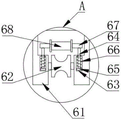
Further, the cable tensioning mechanism comprises two positioning plates which are arranged in parallel, a roller is rotatably connected between the lower ends of the two positioning plates, movable grooves are formed in the inner sides of the two positioning plates, movable rods penetrate through the tops of the movable grooves, a limiting plate is fixed at the lower end of each movable rod, a reset spring is connected between the top of each limiting plate and the top of the inner side of each movable groove, a pressure rod is fixedly connected to the top of each movable rod, a pressure roller is rotatably connected to the outer wall of each pressure rod, the pressure rollers can compress the cables when the cables are guided by the rollers, the cables are tightly attached to the surfaces of the rollers, the cables are prevented from falling off, the cables can be always kept in a straight state in the cable rolling process, the rolling uniformity is increased, downward acting force can be applied to the limiting plates through the arrangement of the reset springs, thereby make the limiting plate drive depression bar and pinch roller extrude the cable downwards.
Furthermore, the driving mechanism comprises a third motor, a driving roller is fixedly mounted on an output shaft of the third motor, the driving roller is in transmission connection with the driven roller ring through a belt, the third motor drives the driving roller to rotate in the winding process, and the driving roller drives the driven roller ring to synchronously rotate through the belt, so that cables in the coils are wound.
Furthermore, one the outside of curb plate is from last to having first motor and second motor down fixed mounting in proper order, the output shaft of first motor passes through shaft coupling and winding roller fixed connection, the output shaft of second motor passes through shaft coupling and threaded rod fixed connection, and during operation, first motor passes through the shaft coupling and drives the winding roller rotation, and simultaneously, the second motor passes through the shaft coupling and drives the threaded rod rotation, and then drives the movable block and remove in the horizontal direction.
Furthermore, two guide rods are fixedly connected between the lower ends of the two side plates, the two guide rods are symmetrically arranged by taking the threaded rod as a symmetry axis, the moving block is connected with the guide rods in a sliding mode, and the moving block is limited by the guide rods, so that the moving block is ensured to move stably.
Furthermore, the bottom four corners of the base are fixedly provided with self-locking universal wheels, the whole winding machine is convenient to move by arranging the self-locking universal wheels, and the use is more flexible and convenient.
Compared with the prior art, the utility model discloses the beneficial effect who reaches is:
1. the utility model discloses a set up first motor, the second motor, the winding roller, the driven roller circle, actuating mechanism, when the wire winding, start first motor and second motor simultaneously, first motor drives the winding roller through the shaft coupling and rotates, simultaneously, the second motor drives the threaded rod through the shaft coupling and rotates, and then drives the movable block and move in the horizontal direction, simultaneously the third motor rotates through driving the drive roll, the drive roll drives the synchronous rotation of driven roller circle through the belt, thereby make the cable in the coil carry out synchronous unwrapping wire, thereby make the winding roller realize evenly rolling up the cable in the rotation process, make things convenient for later stage's arrangement and use, greatly improved the work efficiency of coiling machine;
2. the utility model discloses a set up cable straining device, when the cylinder leads the cable, the pinch roller can compress tightly the cable, make its inseparable with cylinder surface laminating, prevent that the cable from droing to at the in-process of cable rolling, can make the cable remain the state of flare-outing all the time, with the regularity of increase rolling, through reset spring's setting, can apply decurrent effort to the limiting plate, thereby make the limiting plate drive depression bar and pinch roller extrude the cable downwards.
Drawings
The accompanying drawings are included to provide a further understanding of the invention, and are incorporated in and constitute a part of this specification, illustrate embodiments of the invention, and together with the description serve to explain the invention and not to limit the invention. In the drawings:
fig. 1 is a front view of the present invention;
fig. 2 is a side cross-sectional view of the present invention;
fig. 3 is a cross-sectional view of the driven roller ring of the present invention;
fig. 4 is an enlarged schematic view of a portion a of fig. 3 according to the present invention;
fig. 5 is a top view of the guide bar and threaded rod of the present invention;
in the figure: 1. a base; 2. a side plate; 3. a winding roller; 4. a driven roll ring; 5. a coil; 6. a cable tensioning mechanism; 61. positioning a plate; 62. a drum; 63. a movable groove; 64. a movable rod; 65. a limiting plate; 66. a return spring; 67. a pressure lever; 68. a pinch roller; 7. a threaded rod; 8. a moving block; 9. a drive mechanism; 91. a third motor; 92. a drive roll; 10. a support; 11. an arcuate bar; 12. a rotating wheel; 13. a first motor; 14. a second motor; 15. a guide rod.
Detailed Description
The technical solutions in the embodiments of the present invention will be described clearly and completely with reference to the drawings in the embodiments of the present invention, and it is obvious that the described embodiments are only some embodiments of the present invention, not all embodiments. Based on the embodiments in the present invention, all other embodiments obtained by a person skilled in the art without creative work belong to the protection scope of the present invention.
Referring to fig. 1-5, the utility model provides a winding machine with uniform winding, which comprises a base 1, wherein both sides of the top of the base 1 are fixed with side plates 2, a winding roller 3 is rotatably connected between the upper ends of the two side plates 2, a driven roller ring 4 is sleeved on the outer side of the winding roller 3, a coil 5 and a cable tensioning mechanism 6 are sequentially arranged on the inner wall of the driven roller ring 4 along the circumferential direction, the cable tensioning mechanism 6 comprises two positioning plates 61 arranged in parallel, a roller 62 is rotatably connected between the lower ends of the two positioning plates 61, movable grooves 63 are respectively arranged on the inner sides of the two positioning plates 61, movable rods 64 are arranged on the tops of the movable grooves 63 in a penetrating manner, a limiting plate 65 is fixed on the lower ends of the movable rods 64, a return spring 66 is connected between the tops of the limiting plate 65 and the tops of the inner sides of the movable grooves 63, a pressure rod 67 is fixedly connected on the tops of the movable rods 64, the outer wall of the pressing rod 67 is rotatably connected with a pressing wheel 68, when the roller 62 guides the cable, the pressing wheel 68 can press the cable tightly to be tightly attached to the surface of the roller 62 to prevent the cable from falling off, and in the process of winding the cable, the cable can be kept in a straight state all the time to increase the winding uniformity, a downward acting force can be applied to the limiting plate 65 through the arrangement of the reset spring 66, so that the limiting plate 65 drives the pressing rod 67 and the pressing wheel 68 to downwards extrude the cable, a threaded rod 7 is rotatably connected between the lower ends of the two side plates 2, the outer wall of the threaded rod 7 is in threaded connection with a moving block 8, a driving mechanism 9 is fixed at the top of the moving block 8, the driving mechanism 9 is in transmission connection with the driven roller ring 4 through a belt, and symmetrically arranged brackets 10 are fixed on two sides of the top of the moving block 8, the top of support 10 is fixed with arc pole 11, the both ends of arc pole 11 all are rotated and are connected with runner 12, runner 12 rotates with driven roll circle 4 and is connected.
In a preferred embodiment, the driving mechanism 9 includes a third motor 91, an output shaft of the third motor 91 is fixedly mounted with a driving roller 92, the driving roller 92 is in transmission connection with the driven roller ring 4 through a belt, during the winding process, the third motor 91 drives the driving roller 92 to rotate, and the driving roller 92 then drives the driven roller ring 4 to synchronously rotate through the belt, so as to pay off the cable in the coil 5.
In a preferred embodiment, a first motor 13 and a second motor 14 are sequentially and fixedly mounted on the outer side of one side plate 2 from top to bottom, an output shaft of the first motor 13 is fixedly connected with the winding roller 3 through a coupler, an output shaft of the second motor 14 is fixedly connected with the threaded rod 7 through a coupler, during operation, the first motor 13 drives the winding roller 3 to rotate through the coupler, and meanwhile, the second motor 14 drives the threaded rod 7 to rotate through the coupler, so that the moving block 8 is driven to move in the horizontal direction.
In a preferred embodiment, two guide rods 15 are fixedly connected between the lower ends of the two side plates 2, the two guide rods 15 are symmetrically arranged with the threaded rod 7 as a symmetry axis, and the moving block 8 is slidably connected with the guide rods 15, so that the moving block 8 is limited by the guide rods 15, and the moving block 8 is ensured to move stably.
In a preferred embodiment, the four corners of the bottom of the base 1 are fixedly provided with self-locking universal wheels, the whole winding machine can be conveniently moved by arranging the self-locking universal wheels, and the use is more flexible and convenient.
The utility model discloses a theory of operation: when winding, the first motor 13 and the second motor 14 are started simultaneously, the first motor 13 drives the winding roller 3 to rotate through the coupler, meanwhile, the second motor 14 drives the threaded rod 7 to rotate through the coupler, the moving block 8 is further driven to move in the horizontal direction, meanwhile, the third motor 91 drives the driving roller 92 to rotate, the driving roller 92 drives the driven roller ring 4 to synchronously rotate through the belt, and therefore the cable in the coil 5 is synchronously paid off, the cable is uniformly wound by the winding roller 3 in the rotating process, later arrangement and use are facilitated, and the working efficiency of the winding machine is greatly improved; when the cylinder 62 led to the cable, the pinch roller 68 can compress tightly the cable, make its inseparable with cylinder 62 surface laminating, prevent that the cable from droing to at the in-process of cable rolling, can make the cable remain the state of flare-outing all the time, with the regularity that increases the rolling, through reset spring 66's setting, can apply decurrent effort to limiting plate 65, thereby make limiting plate 65 drive depression bar 67 and pinch roller 68 extrude the cable downwards.
It should be noted that, in this document, relational terms such as first and second, and the like are used solely to distinguish one entity or action from another entity or action without necessarily requiring or implying any actual such relationship or order between such entities or actions. Also, the terms "comprises," "comprising," or any other variation thereof, are intended to cover a non-exclusive inclusion, such that a process, method, article, or apparatus that comprises a list of elements does not include only those elements but may include other elements not expressly listed or inherent to such process, method, article, or apparatus.
Finally, it should be noted that: although the present invention has been described in detail with reference to the foregoing embodiments, it will be apparent to those skilled in the art that modifications may be made to the embodiments described in the foregoing embodiments, or equivalents may be substituted for elements thereof. Any modification, equivalent replacement, or improvement made within the spirit and principle of the present invention should be included in the protection scope of the present invention.
Claims (6)
1. The utility model provides an even coiling machine twines, includes base (1), its characterized in that: the wire winding device is characterized in that side plates (2) are fixed on two sides of the top of the base (1), a wire winding roller (3) is rotatably connected between the upper ends of the two side plates (2), a driven roller ring (4) is sleeved on the outer side of the wire winding roller (3), a coil (5) and a cable tensioning mechanism (6) are sequentially arranged on the inner wall of the driven roller ring (4) along the circumferential direction, a threaded rod (7) is rotatably connected between the lower ends of the two side plates (2), a movable block (8) is connected to the outer wall of the threaded rod (7) in a threaded manner, a driving mechanism (9) is fixed on the top of the movable block (8), the driving mechanism (9) is in transmission connection with the driven roller ring (4) through a belt, symmetrically arranged supports (10) are fixed on two sides of the top of the movable block (8), an arc-shaped rod (11) is fixed on the top of each support (10), and rotating wheels (12) are rotatably connected to two ends of each arc-shaped rod (11), the rotating wheel (12) is rotationally connected with the driven roller ring (4).
2. The winding machine capable of winding wires uniformly according to claim 1, wherein: cable straining device (6) include two locating plate (61) that set up side by side, two it is connected with cylinder (62), two to rotate between the lower extreme of locating plate (61) the inboard of locating plate (61) all is equipped with activity groove (63), activity groove (63) top is run through and is equipped with movable rod (64), the lower extreme of movable rod (64) is fixed with limiting plate (65), be connected with reset spring (66) between the top of limiting plate (65) and activity groove (63) inboard top, the top fixedly connected with depression bar (67) of movable rod (64), the outer wall of depression bar (67) rotates and is connected with pinch roller (68).
3. The winding machine capable of winding wires uniformly according to claim 1, wherein: the driving mechanism (9) comprises a third motor (91), an output shaft of the third motor (91) is fixedly provided with a driving roller (92), and the driving roller (92) is in transmission connection with the driven roller ring (4) through a belt.
4. The winding machine capable of winding wires uniformly according to claim 1, wherein: one the outside of curb plate (2) is from last to having first motor (13) and second motor (14) down fixed mounting in proper order, the output shaft of first motor (13) passes through shaft coupling and wire winding roller (3) fixed connection, the output shaft of second motor (14) passes through shaft coupling and threaded rod (7) fixed connection.
5. The winding machine capable of winding wires uniformly according to claim 1, wherein: two guide rods (15) are fixedly connected between the lower ends of the two side plates (2), the two guide rods (15) are symmetrically arranged by taking the threaded rod (7) as a symmetry axis, and the moving block (8) is in sliding connection with the guide rods (15).
6. The winding machine capable of winding wires uniformly according to claim 1, wherein: four corners of the bottom of the base (1) are fixedly provided with self-locking universal wheels.
Priority Applications (1)
| Application Number | Priority Date | Filing Date | Title |
|---|---|---|---|
| CN202220080384.2U CN217229749U (en) | 2022-01-13 | 2022-01-13 | Winding machine with uniform winding |
Applications Claiming Priority (1)
| Application Number | Priority Date | Filing Date | Title |
|---|---|---|---|
| CN202220080384.2U CN217229749U (en) | 2022-01-13 | 2022-01-13 | Winding machine with uniform winding |
Publications (1)
| Publication Number | Publication Date |
|---|---|
| CN217229749U true CN217229749U (en) | 2022-08-19 |
Family
ID=82830567
Family Applications (1)
| Application Number | Title | Priority Date | Filing Date |
|---|---|---|---|
| CN202220080384.2U Active CN217229749U (en) | 2022-01-13 | 2022-01-13 | Winding machine with uniform winding |
Country Status (1)
| Country | Link |
|---|---|
| CN (1) | CN217229749U (en) |
-
2022
- 2022-01-13 CN CN202220080384.2U patent/CN217229749U/en active Active
Similar Documents
| Publication | Publication Date | Title |
|---|---|---|
| CN207108087U (en) | Finished cable coiled body | |
| CN211003770U (en) | Be convenient for papermaking and use coiling mechanism | |
| CN217229749U (en) | Winding machine with uniform winding | |
| CN212151153U (en) | Resistance wire rewinding equipment | |
| CN107055144A (en) | Automatic complexing machine with coiled strip enhanced feature | |
| CN116748294A (en) | Steel strip rolling mill | |
| CN215557702U (en) | Steel coil winding guide equipment | |
| CN210973211U (en) | Glass fiber felt rolling equipment | |
| CN208592249U (en) | Aluminium rolls up unwinding device | |
| CN112390094A (en) | Cable tightening device | |
| CN219688837U (en) | Coiling machine that rolling effect is good | |
| CN219688980U (en) | Wire core braiding leveling mechanism | |
| CN218144731U (en) | Winding machine for processing insulating adhesive tape | |
| CN216671301U (en) | Multi-disc type automatic cable wrapping machine | |
| CN212668710U (en) | Winding device of compound machine | |
| CN211444484U (en) | Cable take-up and pay-off machine | |
| CN218664734U (en) | Winding device for production | |
| CN219729962U (en) | Plastic film lapping roller mechanism | |
| CN220617945U (en) | Wire breakage preventing mechanism for rewinding machine | |
| CN219585536U (en) | Cable take-up reel | |
| CN117079897B (en) | Vertical cabling machine | |
| CN219619441U (en) | Hot air non-woven fabric film winding machine | |
| CN215557598U (en) | Lap changing device for textile lap former | |
| CN218024561U (en) | Novel stable rewinding machine | |
| CN216301562U (en) | Adhesive tape winding machine with quick braking mechanism |
Legal Events
| Date | Code | Title | Description |
|---|---|---|---|
| GR01 | Patent grant | ||
| GR01 | Patent grant |