CN1153367C - Method for adding information on video signal and information auxiliary device - Google Patents
Method for adding information on video signal and information auxiliary device Download PDFInfo
- Publication number
- CN1153367C CN1153367C CNB981195172A CN98119517A CN1153367C CN 1153367 C CN1153367 C CN 1153367C CN B981195172 A CNB981195172 A CN B981195172A CN 98119517 A CN98119517 A CN 98119517A CN 1153367 C CN1153367 C CN 1153367C
- Authority
- CN
- China
- Prior art keywords
- signal
- level
- piece
- information
- value
- Prior art date
- Legal status (The legal status is an assumption and is not a legal conclusion. Google has not performed a legal analysis and makes no representation as to the accuracy of the status listed.)
- Expired - Fee Related
Links
Images


Classifications
-
- H—ELECTRICITY
- H04—ELECTRIC COMMUNICATION TECHNIQUE
- H04N—PICTORIAL COMMUNICATION, e.g. TELEVISION
- H04N5/00—Details of television systems
- H04N5/76—Television signal recording
- H04N5/91—Television signal processing therefor
- H04N5/913—Television signal processing therefor for scrambling ; for copy protection
- H04N2005/91307—Television signal processing therefor for scrambling ; for copy protection by adding a copy protection signal to the video signal
- H04N2005/91321—Television signal processing therefor for scrambling ; for copy protection by adding a copy protection signal to the video signal the copy protection signal being a copy protection control signal, e.g. a record inhibit signal
-
- H—ELECTRICITY
- H04—ELECTRIC COMMUNICATION TECHNIQUE
- H04N—PICTORIAL COMMUNICATION, e.g. TELEVISION
- H04N5/00—Details of television systems
- H04N5/76—Television signal recording
- H04N5/91—Television signal processing therefor
- H04N5/913—Television signal processing therefor for scrambling ; for copy protection
- H04N2005/91307—Television signal processing therefor for scrambling ; for copy protection by adding a copy protection signal to the video signal
- H04N2005/91328—Television signal processing therefor for scrambling ; for copy protection by adding a copy protection signal to the video signal the copy protection signal being a copy management signal, e.g. a copy generation management signal [CGMS]
-
- H—ELECTRICITY
- H04—ELECTRIC COMMUNICATION TECHNIQUE
- H04N—PICTORIAL COMMUNICATION, e.g. TELEVISION
- H04N5/00—Details of television systems
- H04N5/76—Television signal recording
- H04N5/91—Television signal processing therefor
- H04N5/913—Television signal processing therefor for scrambling ; for copy protection
- H04N2005/91307—Television signal processing therefor for scrambling ; for copy protection by adding a copy protection signal to the video signal
- H04N2005/9135—Television signal processing therefor for scrambling ; for copy protection by adding a copy protection signal to the video signal by superimposing the spectrally spread copy protection signal onto the video signal
Abstract
When a spectrally spread additional information signal, obtained by spectrum spreading additional information such as an anti-duplication control signal or copyright information, is superimposed on a video signal, the level of the spectrally spread additional information signal is controlled according to the scatter of pixel values in each block comprising plural pixels. The sensitivity of detecting additional information from the spectrally spread additional information signal is therefore improved, and the visual effect of the spectrally spread additional information signal on a reproduced image is suppressed.
Description
Technical field
The present invention relates to information is added to method and apparatus on the vision signal, wherein Fu Jia information is by spread spectrum, so that the as far as possible little low-down level of the influence of reproduced picture is superposeed, and transmits.
Background technology
At present the various devices of digital-information recording have obtained using widely, for example digital VTR and MD videocorder, but also the DVD device of writing function has appearred having.
In these digital information recording apparatus, various additional informations are recorded with main video and audio signal or computer data.In this case, additional information signal is the digital signal that is recorded on the zone different with the digital information signal district, for example is added to the title in each data block or contents table (its english abbreviation the is TOC) district.
Superpose on by main image signal and under the situation of the system of additional information transmission, additional information signal is not directly to be superimposed upon on the digital information signal, but is recorded on the indirect zone with the title form in routine.Therefore, additional information signal is very easily lost owing to filtering or interference, so record or replay device can not detect necessary additional information signal.Specifically, when the control information and the copyright information that increase as additional information signal, so that when preventing bootlegging, because losing of additional information signal just can not reach original purpose.
In addition, if additional information signal is added on the indirect zone, when digital information signal becomes analog signal, have to main information signal, and additional information signal will be lost so.Even this means increases as the control information of additional information signal and copyright information so that prevent bootlegging, this way also is fully invalid when signal becomes analog signal.
In order to solve the problem that additional information signal is lost when signal becomes analog signal, the inventor has proposed a kind of method, for example prevent that wherein the such additional information signal of reproducing signals is by spread spectrum, during numeral or analog record, the additional information signal of spread spectrum is added on the picture signal and (referring to corresponding US application 08/755101, has now authorized to be USP5982977).
In the method, carry out spread spectrum on the additional information signal by for example being added in the time of enough morning generation PN (pseudo noise) sequence (hereinafter referred to as the PN sign indicating number) with it.So frequency band is narrow, that level the is high such additional information signal of anti-reproduced control signal becomes wide band low level signal, this signal is to not influence of picture signal.Then will be that spread-spectrum signal is added on the analog picture signal with the additional information signal of such method spread spectrum, and be recorded on the recording medium.The picture signal that is recorded on the recording medium both can be simulated, and also can be digital.
In the method, the additional information signal as anti-reproduced control signal with time identical and frequency stack with picture signal.Therefore concerning the people who wants to carry out bootlegging, it is very difficult that the anti-reproduced control signal of stack is removed from picture signal.Yet the additional information signal as the anti-reproduced control signal of stack still is detected and is used when carrying out despreading.
By this way, anti-reproduced control signal is added to the record side with picture signal.In the record side, detect anti-reproduced control signal, and successfully prevent duplicating control according to detected anti-reproduced control signal.
When resetting the additional information that on picture signal, superposes as mentioned above, do not need from signal, to remove this information, therefore need the very low level additional information of stack, it can not impact the reproduced picture of picture signal.Yet, importantly can from main information signal, detect spread-spectrum signal, even level is very low, this just needs to improve the stack level as much as possible, so that reduce the possibility of error detection.
Therefore, when spread-spectrum signal or additional information are added on the picture signal, all will reach gratifying result to the influence of reproduced picture and this two aspect of possibility of error detection, this just need obtain acceptable stack level.
Summary of the invention
The method and apparatus that the purpose of this invention is to provide a kind of additional information can satisfy and reduces the influence of reproduced picture and reduce the requirement of the possibility of error detection additional information.
According to of the present invention information is embedded method on first signal, may further comprise the steps: for the piece value that is contained in described first signal each piece of a plurality of, calculate the distribution level of these piece values, described a plurality of are described and obtain by dividing described first signal; Distribution level according to the piece value of described calculating produces the controlled embedding signal of level with controlled signal level, wherein said signal level is to utilize the level control coefrficient and controlled, and described level control coefrficient is included in the question blank and corresponding to the scope of the distribution level of piece value; And the controlled embedding signal of described level embedded in described first signal.
A kind of information is embedded device on first signal according to of the present invention, comprise: for the piece value that is contained in described first signal each piece of a plurality of, calculate the calculation element of the distribution level of these piece values, wherein said a plurality of are described and obtain by dividing described first signal; Produce the level controller of the controlled embedding signal of level with controlled signal level according to the distribution level of the piece value of described calculating, wherein said signal level is to utilize the level control coefrficient and controlled, and described level control coefrficient is included in the question blank and corresponding to the scope of the distribution level of piece value; And the controlled embedding signal of described level embedded signal superposition device on described first signal.
Human visual characteristic is such, and for example, when very in a small amount noise is added to brightness when changing on the very little image, noise is clearly, yet very violent when the variation of image brightness, even the top noise that superposeed, this noise is also not obvious.
In the present invention, the image light and shade difference in piece is little and scatter very for a short time, and the value of setting of the stack level of these small pieces is just little, and when the image in the piece be when having the fast-changing image of very big distribution, the value of setting of the stack level of piece is with regard to greatly.
Because by this way according to scattering the stack level that can improve spread-spectrum signal, so, also can reduce the possibility of error detection even the additional information of stack is not obvious.
In other words, under the situation of the little image of light and shade difference, additional information stack amount reduces, but as will illustrating later on, concerning the little image of light and shade difference, image and the relation of scattering between the sign indicating number are little, and as will illustrating later on, the detection sensitivity height of this class image, even the stack level reduces, the possibility of error detection can not increase yet.On the other hand, concerning scattering big image, poor to the detection sensitivity of spread-spectrum signal although as will illustrating later on, the level that superposes in the present invention is provided with greatly, and has improved the stack amount, so detection sensitivity has also improved.
To do detailed explanation to the distribution of image with to the relation between the detection sensitivity of spread-spectrum signal below.
Comprise under the situation that is superimposed upon the spread-spectrum signal on the picture signal that at signal Si when detecting spread-spectrum signal, the estimation function φ of despreading can be expressed as follows:
φ=∑si×pi
=∑(Vi+ki×pi)pi
=∑Vi×pi+∑ki×pi×pi ......(1)
Wherein Vi is main information signal, and as picture signal, pi is a spreading code, and as the PN sign indicating number, ki is a coefficient.
In equation (1), first main information signal of expression is the relation between picture signal etc. and the spreading code, the relation between second expression spread-spectrum signal and the spreading code.
Can see that from equation (1) if main information signal is that it doesn't matter or the relation is very little between picture signal etc. and the spreading code, the sensitivity that detects spread-spectrum signal so is just high; Otherwise the relation between picture signal and spreading code is very big, and the sensitivity that detects spread-spectrum signal so is just low.
With the number writing N of the small pieces (=piece) of every screen, the dispersion of image (being equivalent to distributions) writing σ v, the dispersion writing σ p of spreading code, relation function is write γ, obtains:
γ≈(1/N)×∑Vi×pi/(σv×σp)
As σ p=1,
∑Vi×pi≈γ×N×σv
In the equation (1) first is directly proportional with the distribution σ v of image section.Therefore, if the distribution of image section is little, the relation between picture signal and the spreading code is very little so, and first of equation (1) diminishes the detection sensitivity height.On the other hand, when the distribution of image is big, the relation between picture signal and the spreading code is very big so, and first of equation (1) becomes big, and detection sensitivity is low.
As mentioned above, detecting the low part of spread-spectrum signal sensitivity, the stack level of each small pieces of spread-spectrum signal improves, detecting the highly sensitive part of spread-spectrum signal, the stack level of each small pieces of spread-spectrum signal reduces, this depends on every distribution, so error detection is as the possibility reduction of the additional information of spread-spectrum signal.In addition, control stack level by this way can prevent the obvious influence to image of the additional information seen owing to above-mentioned human vision property.
According to the present invention, the picture signal in the module unit further is divided into sub-piece, according to the distribution in each sub-piece, and the stack level of control additional information.
According to the present invention, detect the distribution in the sub-piece, the distribution in the piece is found in the distribution from sub-module unit.Even it is very big that scatter the part in, concerning every, still can detect suitable distribution.
According to the present invention, the picture signal in the module unit further is divided into sub-piece, according to the distribution in the sub-piece, to the stack level of each small pieces of the spread-spectrum signal of each the sub-piece control additional information in.
According to the present invention, according to the distribution in each sub-piece, the stack level of each small pieces changes.Therefore, superimposing additional information more subtly, and can not cause obvious influence to image, and can superimposing additional information, reduce to occur the possibility of error detection etc.Even can not improve the stack level of additional information under the situation about particularly in module unit, scattering, also can improve the stack level in the sub-module unit, therefore improved the sensitivity that detects additional information on the whole.
Description of drawings
Figure 1A to 1C is the figure that is used for describing according to an embodiment of information attachment device of the present invention;
Fig. 2 is the block diagram of an example of using the additional information device of information attachment device of the present invention;
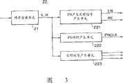
Fig. 3 is the part-structure of device shown in Figure 2;
Fig. 4 is the part-structure of device shown in Figure 2;
Fig. 5 A to 5D represents information signal and as the relation between the stack level of the additional information of spread-spectrum signal;
Fig. 6 is the part-structure of device shown in Figure 2;
Fig. 7 is the block diagram at an example of the device of additional information detection side of an expression embodiment using information stack of the present invention and transmission method;
Fig. 8 A and 8B are the figure of expression another embodiment of the present invention; And
Fig. 9 A and 9B are the expression figure of an embodiment more of the present invention.
Embodiment
Some embodiment that additional information signal are added to the method and apparatus on the picture signal of the present invention are described with reference to the accompanying drawings.Following description is based on such situation, wherein picture signal is a vision signal, this vision signal is to adopt DCT (discrete cosine transform) compress technique as MPEG2 process digital compression, through the vision signal of overcompression in transmission over networks, or transmit by writing down on recording medium, and the such additional information of for example anti-reproduced control signal is by spread spectrum be superimposed upon on the digital video signal.
In the embodiment shown in Figure 1A, a screen (frame or) of vision signal is divided into the piece BL in the rectangle region, and piece BL comprises for example 8 pixels (level) * 8 pixel (vertically), compresses by DCT in these module units BL.By small pieces of spreading code are distributed to a BL, additional information is added on the vision signal as spread-spectrum signal.
According to this embodiment, be superimposed upon on the vision signal as the spread-spectrum signal of additional information, therefore when the value of small pieces of spread-spectrum signal was " 0 ", level (digital signal level) was positive, and when it was " 1 ", level (digital signal level) was born.The stack level of one small pieces is set to a low-down level, and this level can not exert an influence to the replay signal from vision signal.
According to this embodiment, the additional information of stack is anti-reproduced control signal, and the vision signal of transmission is prevented duplicating control.Anti-reproduced control signal for example can be a restricting signal that only allows the first generation to duplicate, or the signal forbidding or allow vision signal to duplicate, and this signal can comprise one or more positions.
In the following embodiments, the spread spectrum sign indicating number is added on the brightness signal Y of vision signal, rather than is superimposed upon on the carrier chrominance signal C.Can certainly be superimposed upon on the carrier chrominance signal C.Yet the carrier chrominance signal of vision signal is for example to transmit as color difference signal by two phase place axle component, and colour is to be reappeared by the phase place of these diaxons.Therefore, on such carrier chrominance signal, even the level of superposed signal is very low so, tone also can change, so signal is apparent in view if spread-spectrum signal is added to.Therefore the stack spread-spectrum signal is very difficult under the situation that does not influence tone.According to this embodiment, spread-spectrum signal only is superimposed upon on the luminance signal, yet, describe simply in order to make, term " vision signal " be will adopt, and brightness signal Y and carrier chrominance signal C do not distinguished.
Fig. 2 is the block diagram of an example of using the additional information device of information attachment device of the present invention.Input analog video signal Vi is become digital signal in A/D converter 11, be applied to effective screen closing unit 12, and after removing the synchronizing signal part, is applied to piece division unit 13.
In piece division unit 13, digital video signal is divided into 8 pixels (level) * 8 pixel (vertically) piece BL unit, shown in Figure 1A.Be sent to the superpositing unit 14 that is used for superimposing additional information from the data in the piece BL unit of piece division unit 13.The additional information that will comprise spread-spectrum signal is then delivered to superpositing unit 14 and stack, so small pieces of spread-spectrum signal are assigned to the data in the piece BL unit, and this will describe below.
The digital video signal that has superposeed above from the additional information of superpositing unit 14 is sent to dct processor 15, in dct processor 15, the data in the piece BL unit are carried out DCT and calculate, so the signal in the time domain is become the DCT coefficient (Figure 1B and 1C) in the frequency domain.
Being sent to quantizer 16 from the result of calculation of dct processor 15 quantizes.The motion-compensated circuit 18 of the output of quantizer 16 is delivered to dct processor 15, component motion is carried out DCT calculate.Specifically, in being called the interior frame of image I, carrying out DCT and calculate, and in the interior frame of image B or image P, get poor between previous frame and the subsequent frames, and will differ from as transfer of data.Yet,, detect the motion vector between the frame, and this component motion is transmitted also in order to reduce this difference as much as possible.
Adopt Huffman code output to quantizer 16 in variable length coder 17 to carry out variable length code, and output is for example with the output signal Dv that notes down and transmit.
Produce additional information as spread-spectrum signal, and stack in the following manner.The analog video signal Vi of input is sent to synchronous separating unit 21.Synchronous separating unit 21 is separated horizontal-drive signal H and vertical synchronizing signal V from analog video signal Vi, horizontal-drive signal H and vertical synchronizing signal V are sent to timing signal unit 22.
Fig. 3 is the block diagram of expression timing signal unit 22.As shown in Figure 3, timing signal unit 22 comprises that PN produces timing signal for generating unit 221, comprises PN clock generating unit 222 and the timing signal for generating unit 223 of PLL.Horizontal-drive signal H and vertical synchronizing signal V from synchronous separating unit 21 are sent to PN generation timing signal for generating unit 221 and timing signal for generating unit 223, and are sent to PN clock generating unit 222 from the horizontal-drive signal H and the vertical synchronizing signal V of synchronous separating unit 21.
PN produces timing signal for generating unit 221 and utilizes horizontal-drive signal H and vertical synchronizing signal V to produce vertical synchronization reset signal RE, is identified for the repetition period of the spread spectrum PN sign indicating number sequence of spread spectrum.PN produces timing signal for generating unit 221 and also produces PN generation permission signal EN.
Adopt the PN clock generating unit 222 of PLL circuit to produce PN clock signal PNCLK, this signal and horizontal-drive signal H are synchronous, and have the view data cycle of piece BL unit.Specifically, PN clock signal PNCLK has the clock signal that the cycle equals the data among the piece BL, and in this example, the cycle of a piece BL is 8 * 8=64 pixel.PN clock signal PNCLK determines the cycle of the small pieces of spreading code.
Timing signal for generating unit 223 produces the various timing signals that are used at the device of Fig. 2 vision signal being carried out digitlization and compression according to horizontal-drive signal H and vertical synchronizing signal V.Comprise clock in the elementary area from the timing signal of timing signal for generating unit 223.
PN generation from timing signal unit 22 allows signal EN, reset signal RE and PN clock signal PNCLK to be sent to PN generation unit 23.
Fig. 4 represents an example of the structure of PN generation unit 23.This routine PN generation unit 23 comprises the d type flip flop REG1-REG15 that forms 15 grades of shift registers, and the XOR circuit EX-OR1-EX-OR3 that the suitable output branch of shift register is calculated.PN generation unit 23 shown in Figure 4 produces according to PN and allows signal EN, PN clock signal PNCLK and PN sign indicating number reset signal RE to produce M PN sign indicating number sequence PS.
The PN sign indicating number sequence PS that obtains from PN generation unit 23 is sent to spread spectrum (in this manual, SS represents spread spectrum) additional information generation unit 24 by this way.Spread spectrum additional information generation unit 24 comprises one with above-mentioned anti-reproduced control signal and the multiplier that multiplies each other from the PN sign indicating number sequence PS of PN generation unit 23, and produces the anti-reproduced control signal of spread spectrum as the spread spectrum additional information.In this case, provide by spread spectrum additional information generation unit 24 or in a piece BL, have identical information bit content at least by the anti-reproduced control signal of spread spectrum additional information generation unit 24 spread spectrums.
Spread spectrum additional information generation unit 24 provides the anti-reproduced control signal of spread spectrum of production to superpositing unit 14 by stack electrical level control unit 25 then.
In this case, according to the value that spread spectrum is prevented small pieces of reproduced control signal, stack electrical level control unit 25 output digital levels.When the value of small pieces of the anti-reproduced control signal of spread spectrum is " 0 ", it be one very little on the occasion of, when the value of small pieces of the anti-reproduced control signal of spread spectrum was " 1 ", it was a very little negative value.These stack level are according to the variable control of distribution among the every BL.
In order to control the stack level in the stack electrical level control unit 25, be sent to distribution computing unit 26, the distribution of the intensity level among the computing block BL from the view data in the module unit of piece division unit 13.In this case, scattering σ v is provided by following formula:
σv=∑(Vi-Veven)
2/M ......(2)
Wherein the value of each pixel is Vi in the piece, and the mean value of all pixels is Veven in the piece.Herein, M is the number of pixel in the piece, according to present embodiment, and M=64.Be sent to stack electrical level control unit 25 from the distribution result of calculation of scattering computing unit 26.
Stack electrical level control unit 25 comprises tracing table 251, tracing table 251 be stored in the distribution σ v in the piece BL unit with the coefficient that is used for determining the stack level between corresponding relation, also comprise mlultiplying circuit 252, mlultiplying circuit 252 is that the level that superposes is provided with the unit.Tracing table 251 for example can be a type shown in Figure 6.Specifically, meet the following conditions when scattering σ v:
0≤σv<a,
The value of the multiplier of finding from tracing table 251 is " 1 ".Meet the following conditions when scattering σ v:
a≤σv<b,
The value of the multiplier of finding from tracing table 251 is " 2 ".Meet the following conditions when scattering σ v:
b≤σv,
The value of the multiplier of finding from tracing table 251 is " 3 ".
In mlultiplying circuit 252, according to small pieces value " 0 " or " 1 " of spread-spectrum signal, the initial value of the very little plus or minus that presets multiplies each other with the multiplier of taking from tracing table 251.Obtain spread-spectrum signal from stack the electrical level control unit 25 thus, the stack level of this signal is that the distribution according to the image in every obtains, and this signal is sent to superpositing unit 14, is superimposed upon on the view data in the module unit.In other words, shown in the dash area of Figure 1B, be plus or minus and have signal according to the distribution of the pixel value in the piece by on all pixels among the piece BL that is added to equably according to the small pieces value.
Concerning every of vision signal, very big when in piece, scattering, even and superpose, when noise was also remarkable, additional information was that each small pieces of spread-spectrum signal superpose with height stack level, if superpose, when noise was remarkable, each small pieces was with the stack of low stack level.Therefore, spread-spectrum signal is superimposed on the vision signal, and therefore the additional information of stack is not remarkable, and can improve the sensitivity that detects spread-spectrum signal.
In this case, when the signal from superpositing unit 14 is carried out dct transform, the additional information component of the spread-spectrum signal of stack will be concentrated in coefficient DC, and coefficient DC is the DC component of all DCT coefficients, shown in Fig. 1 C.
According to present embodiment, as describing following, by carried out spread spectrum before carrying out anti-dct transform, the DC component of only extracting the DCT coefficient from the DCT coefficient is coefficient DC, can detect in vision signal as the anti-reproduced control signal of the spread spectrum of additional information stack.
Decoded when the video data of transmission, and when carrying out anti-dct transform,, coefficient DC prevent reproduced control signal because comprising spread spectrum, so this spread spectrum prevents that reproduced control signal is decoded, vision signal is caused adverse effect hardly.Under the situation of high fdrequency component, compression can cause loss of data, is the coefficient DC of DC component but exist really in compressed signal.Therefore, the anti-reproduced control signal of spread spectrum is transmitted like clockwork, and correctly prevents duplicating control.
Fig. 5 A to 5D represents information signal and as the relation between the stack level of the additional information of spread-spectrum signal.Anti-reproduced control signal is a low bit rate signal that only comprises a little information, and is a narrow-band signal, shown in Fig. 5 A.When this signal during, just become broadband signal, shown in Fig. 5 B by spread spectrum.The signal level and the bandwidth expansion ratio of spread spectrum descend inversely.
This spread-spectrum signal is superimposed upon on the information signal by superpositing unit 14, and in this course, the stack level ratio of the anti-reproduced control signal of spread spectrum is little as the dynamic range of the vision signal of information signal, shown in Fig. 5 C.Therefore, the adverse effect to vision signal or out of Memory signal that causes owing to stack almost can be avoided fully.When the top vision signal that has superposeed spread-spectrum signal was delivered to monitor and playback of video signal, spread-spectrum signal did not almost have any influence, and can obtain reproduced picture clearly.
On the other hand, as will be described below, so that when detecting the spread-spectrum signal of stack, spread-spectrum signal is resumed into narrow-band signal, shown in Fig. 5 D when carrying out despreading.By the spread spectrum coefficient of enough bandwidth is provided, the power of the additional information signal behind the despreading surpasses the power of information signal, so it just can be detected.
In this case, the additional information signal that is superimposed upon on the vision signal etc. has time identical with vision signal and frequency, therefore replaces and can not delete or change by rejection frequency or simple information.
By required additional information signal and the record of stack on vision signal, it can be attached on the vision signal, and additional information signal such as above-mentioned anti-reproduced control signal can transmit like clockwork.In addition, on the spread spectrum additional information signal was added to vision signal, perhaps the signal power of information signal was lower than additional information signal, and the distortion of information signal can reduce to minimum so.
In the time of when for example anti-reproduced control signal is added to vision signal as additional information signal on, it is very difficult changing or remove anti-reproduced control signal, and therefore anti-reproduced control signal can prevent bootlegging really.
In addition,, adopt the PN sign indicating number sequence that has according to the vertical cycle of vertical synchronizing signal, carry out spread spectrum according to said structure.According to from video signal detection to the synchronous signal of vertical synchronizing signal, can be easy to produce the PN sign indicating number sequence that is used for spread spectrum, need to detect this spread-spectrum signal from vision signal.In other words, not needing is the Synchronization Control that despreading carries out the PN sign indicating number by the slip correction device for example.Can produce the PN sign indicating number sequence that is used for despreading by this way at an easy rate, can promptly carry out despreading, and can detect by spread spectrum and the anti-reproduced control signal or other additional information that are added on the vision signal.
In Fig. 2 example, the anti-reproduced control signal of spread spectrum is added on the digital video signal, but on the analog video signal that also can be added to before carrying out A/D conversion, so small pieces of spread-spectrum signal are corresponding to a plurality of pixels, and these pixels are corresponding to the data in the piece BL unit.
Fig. 7 represents a kind of like this embodiment of device, and superposeed from the above compressed vision signal of spread spectrum additional information of this device is recovered original video data, and detects the anti-reproduced control signal as additional information.
As shown in Figure 7, for example be sent to variable-length decoder 31 by the video data Dv that reads the compression that DVD dish obtains, decoded there, and deliver to inverse DCT 32.By carry out inverse quantization in inverse DCT 32, data are resumed the bit stream that becomes to comprise the DCT coefficient.Data from inverse DCT 32 are sent to anti-dct processor 33, and anti-dct processor 33 becomes these data the view data of time domain from the DCT coefficient of frequency domain.Deliver to piece division unit 34 from the signal of anti-dct processor 33 outputs, piece division unit 34 recovers to have the view data of original time sequencing from piece BL cell data, and these data revert to analog video data by D/A converter 35.
The situation of the detection additional information of this example is described below.The bit stream data that comprises the DCT coefficient from inverse DCT 32 is sent to DC component extraction unit 41, and extraction is the coefficient DC of the DC component of DCT coefficient.
This coefficient DC is sent to adder 42, and adder 42 is the poor addition between interior frame such as image B and the image P, and extracts correct data.The output signal of adder 42 temporarily exists in the DC component memory 43.DC component memory 43 comprises the memory block that the frame in the module unit is used, and the recording areas of each module unit is exported renewal by the refreshing of corresponding clock from adder 42.Be sent to an input of switching circuit 44 from every DC component output of DC component memory 43.In addition, zero (" 0 ") delivers to another input of switching circuit 44 as DC component.
According to the interior frame or the interior frame information that in the header information of the input digit packed data of variable-length decoder, obtain, switch and control switch circuit 44.In other words, when the data of decompress(ion) were the interior frame data of image I, switching circuit 44 switched to " 0 ".At this moment the data among the piece BL are the data that are included in the frame, and are the data of the particular frame all different with the frame of the frame of front and back.
On the other hand, when the data of decompress(ion) were interior frame data, switching circuit 44 switched to DC component memory 43, and every difference is stored in the memory 43, the data addition of the frame of this difference and back, and recover correct data.
As mentioned above, the DC component of the DCT coefficient of recovery is sent to despreading unit 45.Simultaneously, the PN sign indicating number sequence synchronous with the PN sign indicating number of stack side is sent to despreading unit 45, carries out despreading, and the additional information that is superimposed upon on the DCT coefficient DC component is detected.In this case, when distribution according to above-mentioned image, the DC component of the DCT coefficient of some part of piece increases, the detection sensitivity of despreading unit 45 also improves, additional information as spread-spectrum signal in these parts does not produce obviously influence to reproduced picture, and can detect the additional information of stack like clockwork.Detected additional information is sent to additional information determining unit 46, determines the position of additional information there.
Produce as follows and the synchronous PN sign indicating number sequence that is used for despreading of stack side.The video signal data Dv of compression is sent to synchronization timing extraction unit 47, produces synchronous timing signal.This signal comprises the piece timing signal or the synchronous timing signal of data in the frame unit.Synchronous timing signal from synchronization timing extraction unit 47 is sent to timing signal for generating unit 48, produces the timing signal as the clock that is used for decompress(ion) and the timing signal of the spreading code that is used to produce despreading there.
The extended code that is used for despreading has PN generation unit 49 to produce.PN generation unit 49 has the structure identical with PN generation unit shown in Figure 4.Timing signal for generating unit 48 produces synchronous reset signal RE according to the synchronous timing signal from synchronization timing extraction unit 47, ENABLE signal EN and
Clock signal PNCLK, they are synchronous with the timing signal that is used for spread spectrum additional information stack side, and are sent to PN generation unit 49.
By the PN sign indicating number sequence synchronous PN sign indicating number sequence of PN generation unit 49 generations with the stack side.Because the effect from the PN sign indicating number sequence of PN generation unit 49 detects additional information in despreading unit 45 from the output signal of adder 42.
Therefore according to present embodiment, owing to detect and be confirmed as the anti-reproduced control signal of additional information, just can detect duplicating of the video data that whether may carry out bit stream, digital compression.If forbid duplicating, abandon the bit stream data in the buffer so, do not read this data.
If only need to detect additional information, as anti-reproduced control signal, so just do not need anti-dct processor, so additional information detection means has simpler structure, cost is low.
For example, DVD player or DVD videocorder comprise mpeg decoder, therefore being used for the MPEG2 compressed video signal is reverted to time-base signal, is after the based video signal, additional information to be carried out despreading and detection when compressed video signal being carried out the DCT processing and it is reverted to naturally.
Yet the DVD-ROM driver does not possess the MPEG2 decoder, therefore to the decoding of MPEG be with personal computer that the DVD-ROM driver links to each other in finish.In this case, if before mpeg decode, just prevented bootlegging, so just can carry out the effectively anti-control of duplicating.
If the additional information detection means that comprises part 31,32 shown in Figure 7,41-49 is provided in the DVD-ROM driver, so just can be without expensive component such as mpeg decoder, bit stream data prevents duplicating control and other processing.
Suitably be connected between DVD driver and the personal computer if will comprise the additional information detection means of part 31,32 shown in Figure 7,41-49, so just can obtain identical effect.
Certainly, can from the DC component of above-mentioned DCT coefficient, not detect additional information, but detect additional information in the data of the piece BL unit of always reflexive dct processor 33.
In addition, in the above-described embodiments, carry out spread spectrum by the PN sign indicating number sequence that has vertical cycle, and frame is poor in considering, adder 42 and DC component memory 43 are provided, if but when having the PN sign indicating number sequence inversion of vertical cycle to additional information spread spectrum and when stack with the frame period with difference of 1, adder 42 and DC component memory 43 just can omit so.
In the above-described embodiments, scatter the mean value that computing unit 26 adopts all pixels among the piece BL,, all pixels among the piece BL are determined to scatter σ v by above-mentioned equation (2).Yet piece BL can further be divided into sub-piece, considers the distribution in this a little module unit, determines the stack level of each small pieces of spread-spectrum signal in the module unit.
For example, shown in Fig. 8 A, comprise that the piece BL of the individual pixel in 8 (level) * 8 (vertically) can be divided into four 4 * 4 sub-piece SB1, SB2, SB3 and SB4, and determine to scatter σ v1, σ v2, σ v3 and σ v4, shown in Fig. 8 B by above-mentioned formula (2).By calculating the distribution σ v that can obtain piece BL, for example mean value of the distribution of each sub-piece
σv=(σv1+σv2+σv3+σv4)/4,
And the stack level that obtains from the distribution of piece BL unit, as among the above-mentioned embodiment.
When from the distribution of sub-piece SB1, SB2, SB3 and SB4, determining the distribution of piece BL by this way, from more detailed image content information, determine the stack level of additional information.Purpose of the present invention the objective of the invention is to make additional information not obvious in the image of resetting, and improves detection sensitivity, so can realize in more effective mode.
In addition, when piece was divided into sub-piece, the stack level of spread-spectrum signal small pieces was not fixed in piece BL, but can change according to the distribution in the sub-piece.
Fig. 9 A and 9B represent a such example.Specifically, in Fig. 9 A, piece BL is divided into four sub-piece SB1, SB2, SB3 and SB4 as top example, utilizes formula (2) that each sub-piece SB1, SB2, SB3 and SB4 are determined to scatter σ v1, σ v2, σ v3 and σ v4.Scatter σ v1, σ v2, σ v3 and σ v4 according to these then and determine stack level in each sub-module unit.
In this case, there are two kinds of methods to set stack level in the sub-module unit.A kind of method is to search the tracing table 251 in the sub-module unit, so that change the stack level.
Another kind method is, distribution σ v in the mean value calculation module unit of distribution σ v1, σ v2, σ v3 and σ v4 from sub-module unit, search tracing table 251 (from tracing table, obtaining the result) according to scattering σ v, determine the position of coefficient (in piece) according to distribution σ v1, σ v2, σ v3 and the σ v4 of each sub-piece.
A kind of method in back is shown in Fig. 9 B.For example, suppose that working as multiplier is 2, this multiplier is the result who obtains according to the distribution σ v of tracing table from module unit, and the distribution in the antithetical phrase piece keeps such relation:
σv1>σv2>σv4>σv3。
Then multiplier is distributed to sub-module unit, shown in Fig. 9 B, so piece BL as a whole, multiplier is " 2 ".
In these two kinds of methods, the stack level in the small pieces is unfixed, but changes in sub-module unit.As a result, under the situation of present embodiment, additional information no longer only is included in the DC component of DCT coefficient, and after carrying out anti-dct transform to the Data Detection additional information in the module unit.
In above description, distribute to one situation according to small pieces, the spread spectrum additional information is superimposed upon on the vision signal, however small pieces can be assigned to one or more.For example, can superpose like this, make four the corresponding small pieces of a microlith.
In addition, can superpose like this, promptly not that small pieces are distributed to wherein every one or more of comprising a plurality of pixels on horizontal direction and the vertical direction, but distribute to wherein every or comprise horizontal direction or comprise one or more of a plurality of pixels on the vertical direction.
In addition, the invention is not restricted to the situation that view data is compressed and transmits, but any situation that small pieces that can be used for spread-spectrum signal are assigned to module unit and are applied.
In addition, the reset cycle of the spreading code of spread-spectrum signal can not be a vertical cycle, and can be a plurality of vertical cycles.The reset cycle of spreading code also can be one or more horizontal cycles.
In the above-described embodiments, according to the value of " 0 " or " 1 " of the small pieces of spreading code, with the stack level or be set to positive or be set to bear, but a level can be 0 level, and another or just or negative.In this case, the present invention can adopt or the stack level of the said fixing pattern of plus or minus level.
In above description, is anti-reproduced control signal by spread spectrum with the additional information signal that is added on the vision signal, yet additional information is not limited to anti-reproduced control signal, also can be for example relevant with digital video signal information, or discern the timing code of every or copyright information, or the like.As copyright information, for example can adopt the sequence number of designated recorder device.If this sequence number stack also is recorded on the digital video signal Vi, so just can follow the tracks of the history of duplicating at an easy rate.
In above description, spread-spectrum signal is added on the digital video signal, but on the analog video signal that also it can be added to, in this case, still can use the present invention.In addition, not only additional information can be added on the vision signal as spread-spectrum signal, but also on the picture signal of the image read from image analyzer of for example can being added to.
According to above embodiment, utilize the PN sign indicating number to the preamble bit spread spectrum, yet can superpose PN sign indicating number sequence different, and detect spread-spectrum signal by detecting these PN sign indicating numbers according to preamble bit.
The present invention also can be used for by limiting transmission " 1 " when the stack PN sign indicating number, and transmits " 0 " when not superposeing, with the PN sign indicating number as be added to occasion on the vision signal of spread-spectrum signal.
In addition, spreading code is not limited to the PN sign indicating number, can be other sign indicating number also, as gold code.
In above description, the present invention can be used for record and playback system, but also can be used for additional information is superimposed upon on the vision signal, and by various medium, as the occasion of radio wave, cable or infrared transmission.
Claims (24)
1. one kind embeds method on first signal with information, may further comprise the steps:
For the piece value that is contained in each piece of a plurality of in described first signal, calculate the distribution level of these piece values, described a plurality of are described and obtain by dividing described first signal;
Distribution level according to the piece value of described calculating produces the controlled embedding signal of level with controlled signal level, wherein said signal level is to utilize the level control coefrficient and controlled, and described level control coefrficient is included in the question blank and corresponding to the scope of the distribution level of piece value; And
The controlled embedding signal of described level is embedded in described first signal.
2. according to the method on first signal that information is embedded of claim 1, the distribution level of wherein said value forms first level that scatters, this method also comprises such step: the second distribution level that calculates the sub-piece value that is contained in the sub-piece, this sub-piece is further divided piece described in described first signal and is obtained, and the described first distribution level of described value is to scatter level according to described second of described sub-piece value to calculate.
3. according to the method on first signal that information is embedded of claim 1, wherein said distribution level is that the number that utilizes the mean value of described value, described value and be contained in described described value in described first signal calculates.
4. according to the method on first signal that information is embedded of claim 1, the step of the controlled embedding signal of wherein said generation level may further comprise the steps:
According to first level of described distribution, determine the first level control coefrficient from described level control coefrficient;
According to second level of described first level control coefrficient and described distribution, be identified for controlling the second level control coefrficient of the described embedding signal level that will embed in the described sub-piece;
The described level of described embedding signal is controlled in utilization corresponding to the described second level control coefrficient of each sub-piece of sub-piece described in described first signal.
5. according to the method on first signal that information is embedded of claim 1, wherein said first signal is a vision signal, divide the pixel block that obtains for a plurality of images for described, and described value is the piece pixel value that is contained among described of described a plurality of pixels to described vision signal.
6. according to the method on first signal that information is embedded of claim 1, wherein said embedding signal is that the additional information from the expression copyright information produces.
7. according to the method on first signal that information is embedded of claim 1, wherein said copyright information forbids or allows to duplicate the copy control information of described first signal for expression.
8. according to the method on first signal that information is embedded of claim 1, comprise also producing a kind of yard step that wherein said embedding signal utilizes additional information and described sign indicating number to produce.
9. method on first signal that information is embedded according to Claim 8, wherein said sign indicating number is a kind of spreading code, and described embedding signal produces by utilizing the described additional signal of described sign indicating number spread spectrum.
10. method on first signal that information is embedded according to Claim 8, wherein said embedding signal produces by utilizing described sign indicating number that described additional signal is carried out spread processing.
11. method on first signal that information is embedded according to Claim 8, wherein said sign indicating number is a kind of Pseudo-Random Noise Code.
12. method on first signal that information is embedded according to Claim 8, wherein said sign indicating number comprises the unit gap corresponding to each piece in the piece described in described first signal, the controlled embedding signal of described level is by the described signal level of control corresponding to described embedding signal interior during the described unit gap, and produce according to described first dispersion grade of corresponding blocks in described first signal, and the controlled embedding signal of described level is to embed by the corresponding blocks that during described in the controlled embedding signal of described level each is embedded described first signal.
13. one kind embeds device on first signal with information, comprising:
For the piece value that is contained in each piece of a plurality of in described first signal, calculate the calculation element of the distribution level of these piece values, wherein said a plurality of are described and obtain by dividing described first signal;
Produce the level controller of the controlled embedding signal of level with controlled signal level according to the distribution level of the piece value of described calculating, wherein said signal level is to utilize the level control coefrficient and controlled, and described level control coefrficient is included in the question blank and corresponding to the scope of the distribution level of piece value; And
The controlled embedding signal of described level is embedded signal superposition device on described first signal.
14. information is embedded device on first signal according to claim 13, the distribution level of wherein said value forms first level that scatters, calculate second level of the distribution that is contained in the sub-piece value in the sub-piece with described calculation element, this sub-piece is further divided piece described in described first signal and is obtained, and calculates described first level of the distribution of described value according to described second level of the distribution of described sub-piece value.
15. according to claim 13 information is embedded device on first signal, the number that wherein said calculation element utilizes the mean value of described value, described value and is contained in described described value in described first signal calculates the level of described distribution.
16. information is embedded device on first signal according to claim 13, wherein said level controller calculates the first level control coefrficient according to first level of described distribution from described level control coefrficient, calculate to be used to control according to second level of described first level control coefrficient and described distribution and will embed the second level control coefrficient that embeds the level of signal described in the described sub-piece, and utilize the described level of controlling described embedding signal corresponding to each the described second level control coefrficient of piece described in described first signal.
17. information is embedded device on first signal according to claim 13, wherein said first signal is a vision signal, divide the pixel block that obtains for a plurality of images for described, and described value is the piece pixel value that is contained among described of described a plurality of pixels to described vision signal.
18. according to claim 13 information is embedded device on first signal, wherein said embedding signal is that the additional information from the expression copyright information produces.
19. according to claim 13 information is embedded device on first signal, wherein said copyright information forbids or allows to duplicate the copy control information of described first signal for expression.
20. according to claim 13 information is embedded device on first signal, comprise also being used to produce a kind of yard sign indicating number generation device that wherein said embedding signal utilizes additional information and described sign indicating number to produce.
21. according to claim 20 information is embedded device on first signal, wherein said sign indicating number is a kind of spreading code, and described embedding signal produces by utilizing the described additional signal of described sign indicating number spread spectrum.
22. according to claim 20 information is embedded device on first signal, wherein said embedding signal produces by utilizing described sign indicating number that described additional signal is carried out spread processing.
23. according to claim 20 information is embedded device on first signal, wherein said sign indicating number is a kind of Pseudo-Random Noise Code.
24. information is embedded device on first signal according to claim 20, wherein said sign indicating number comprises the unit gap corresponding to each piece in the piece described in described first signal, the controlled embedding signal of described level is by the described signal level of control corresponding to described embedding signal interior during the described unit gap, and produce according to described first level of the distribution of corresponding blocks in described first signal, and the controlled embedding signal of described level is to embed by the corresponding blocks that during described in the controlled embedding signal of described level each is embedded described first signal.
Applications Claiming Priority (3)
| Application Number | Priority Date | Filing Date | Title |
|---|---|---|---|
| JP252176/97 | 1997-09-17 | ||
| JP252176/1997 | 1997-09-17 | ||
| JP25217697A JP4003098B2 (en) | 1997-09-17 | 1997-09-17 | Information addition method and information addition apparatus for image signal |
Publications (2)
| Publication Number | Publication Date |
|---|---|
| CN1218956A CN1218956A (en) | 1999-06-09 |
| CN1153367C true CN1153367C (en) | 2004-06-09 |
Family
ID=17233560
Family Applications (1)
| Application Number | Title | Priority Date | Filing Date |
|---|---|---|---|
| CNB981195172A Expired - Fee Related CN1153367C (en) | 1997-09-17 | 1998-09-16 | Method for adding information on video signal and information auxiliary device |
Country Status (8)
| Country | Link |
|---|---|
| US (1) | US6359999B1 (en) |
| EP (1) | EP0903939B1 (en) |
| JP (1) | JP4003098B2 (en) |
| KR (1) | KR100576382B1 (en) |
| CN (1) | CN1153367C (en) |
| CA (1) | CA2246509A1 (en) |
| DE (1) | DE69833243T2 (en) |
| TW (1) | TW398117B (en) |
Families Citing this family (10)
| Publication number | Priority date | Publication date | Assignee | Title |
|---|---|---|---|---|
| JPH1173725A (en) | 1997-08-29 | 1999-03-16 | Sony Corp | Information signal recording/reproducing system, information recording device, information signal reproducing device and information signal recording/ reproducing method |
| US6823074B1 (en) | 1997-09-17 | 2004-11-23 | Pioneer Corporation | Digital-watermark superposing apparatus and digital-watermarker detecting apparatus |
| JP2001111808A (en) * | 1999-10-05 | 2001-04-20 | Nec Corp | Electronic watermark data inserting system and device |
| JP3511502B2 (en) * | 2000-09-05 | 2004-03-29 | インターナショナル・ビジネス・マシーンズ・コーポレーション | Data processing detection system, additional information embedding device, additional information detection device, digital content, music content processing device, additional data embedding method, content processing detection method, storage medium, and program transmission device |
| US7054362B1 (en) | 2001-05-29 | 2006-05-30 | Cisco Technology, Inc. | Methods and apparatus for updating a reduction ratio |
| US7162097B1 (en) | 2001-05-29 | 2007-01-09 | Cisco Technology, Inc. | Methods and apparatus for transform coefficient filtering |
| US6763070B1 (en) * | 2001-05-29 | 2004-07-13 | Cisco Technology, Inc. | Methods and apparatus for selecting a cut-off index |
| US20040008265A1 (en) * | 2002-07-13 | 2004-01-15 | Q Wireless, L.L.C. | Wireless spread spectrum video communications device |
| US7792184B2 (en) * | 2003-04-24 | 2010-09-07 | Qualcomm Incorporated | Apparatus and method for determining coefficient of an equalizer |
| ITTO20110906A1 (en) * | 2011-10-11 | 2013-04-12 | Csp A Innovazione Nelle Ict Scarl | METHOD AND SYSTEM TO GENERATE A MODULAR SIGNAL AS WELL AS METHOD AND SYSTEM TO PROCESS A MODULAR SIGNAL |
Family Cites Families (18)
| Publication number | Priority date | Publication date | Assignee | Title |
|---|---|---|---|---|
| US4969041A (en) * | 1988-09-23 | 1990-11-06 | Dubner Computer Systems, Inc. | Embedment of data in a video signal |
| US5319735A (en) * | 1991-12-17 | 1994-06-07 | Bolt Beranek And Newman Inc. | Embedded signalling |
| EP0584966B1 (en) * | 1992-08-26 | 1999-04-14 | Hewlett-Packard Company | Pixel image edge-smoothing method and system |
| US5805762A (en) * | 1993-01-13 | 1998-09-08 | Hitachi America, Ltd. | Video recording device compatible transmitter |
| JP3250333B2 (en) * | 1993-04-02 | 2002-01-28 | ソニー株式会社 | Video signal processing method, video signal recording method, video signal reproduction method, video signal processing device, video signal recording device, and video signal reproduction device |
| US5857038A (en) * | 1993-06-29 | 1999-01-05 | Canon Kabushiki Kaisha | Image processing apparatus and method for synthesizing first and second image data |
| JP3548225B2 (en) * | 1994-04-28 | 2004-07-28 | キヤノン株式会社 | Image processing apparatus and image processing method |
| JP3371187B2 (en) * | 1995-12-04 | 2003-01-27 | ソニー株式会社 | Information signal recording apparatus and method, and information signal duplication apparatus and method |
| US5901178A (en) * | 1996-02-26 | 1999-05-04 | Solana Technology Development Corporation | Post-compression hidden data transport for video |
| JPH09238093A (en) * | 1996-02-29 | 1997-09-09 | Sanyo Electric Co Ltd | Spread spectrum receiver |
| US5949885A (en) * | 1996-03-12 | 1999-09-07 | Leighton; F. Thomson | Method for protecting content using watermarking |
| US5848155A (en) * | 1996-09-04 | 1998-12-08 | Nec Research Institute, Inc. | Spread spectrum watermark for embedded signalling |
| JP3778236B2 (en) * | 1996-10-22 | 2006-05-24 | ソニー株式会社 | Video signal transmission method, video signal output method, video signal output device, and additional information detection device |
| US5825892A (en) * | 1996-10-28 | 1998-10-20 | International Business Machines Corporation | Protecting images with an image watermark |
| JP3700738B2 (en) * | 1996-11-18 | 2005-09-28 | ソニー株式会社 | Information output device, information output method, recording device, and recording method |
| JPH10174070A (en) * | 1996-12-10 | 1998-06-26 | Sony Corp | Method for transmitting video signal, method for extracting superimposed information, video signal output device, video signal recording device and video signal recording medium |
| JPH10174063A (en) * | 1996-12-10 | 1998-06-26 | Sony Corp | Video signal transmitting method, superimposed information extracting method, video signal output device, video signal receiver and video signal recording medium |
| JPH10191244A (en) * | 1996-12-19 | 1998-07-21 | Sony Corp | Video signal transmission method, overlap information extraction method, video signal output device, video signal reception device and video recording medium |
-
1997
- 1997-09-17 JP JP25217697A patent/JP4003098B2/en not_active Expired - Fee Related
-
1998
- 1998-09-04 TW TW87114727A patent/TW398117B/en not_active IP Right Cessation
- 1998-09-04 CA CA 2246509 patent/CA2246509A1/en not_active Abandoned
- 1998-09-10 DE DE1998633243 patent/DE69833243T2/en not_active Expired - Fee Related
- 1998-09-10 EP EP19980307312 patent/EP0903939B1/en not_active Expired - Lifetime
- 1998-09-10 KR KR1019980037425A patent/KR100576382B1/en not_active IP Right Cessation
- 1998-09-11 US US09/151,272 patent/US6359999B1/en not_active Expired - Fee Related
- 1998-09-16 CN CNB981195172A patent/CN1153367C/en not_active Expired - Fee Related
Also Published As
| Publication number | Publication date |
|---|---|
| CN1218956A (en) | 1999-06-09 |
| KR100576382B1 (en) | 2006-11-07 |
| EP0903939B1 (en) | 2006-01-18 |
| CA2246509A1 (en) | 1999-03-17 |
| EP0903939A3 (en) | 1999-03-31 |
| DE69833243T2 (en) | 2006-09-28 |
| JP4003098B2 (en) | 2007-11-07 |
| EP0903939A2 (en) | 1999-03-24 |
| JPH1198475A (en) | 1999-04-09 |
| DE69833243D1 (en) | 2006-04-06 |
| US6359999B1 (en) | 2002-03-19 |
| KR19990029702A (en) | 1999-04-26 |
| TW398117B (en) | 2000-07-11 |
Similar Documents
| Publication | Publication Date | Title |
|---|---|---|
| US7444031B2 (en) | Image processing apparatus | |
| CN1180633C (en) | Arrangement and method for processing video data | |
| CN1153367C (en) | Method for adding information on video signal and information auxiliary device | |
| CN1130911C (en) | Information signal reproduction control system | |
| CN1255793A (en) | Copied generation administrative method, information signal recorder, output device and reproduction device | |
| CN1078426C (en) | Bit-stream allocating and restoring method for digital vcr and data compressing/decompressing apparatus using the same | |
| CN1033785C (en) | Improved video signal recording system | |
| CN1108673C (en) | Additional information superimposing device | |
| CN1198063A (en) | Video signal transmission device, video signal output device, video signal reception device, video signal duplication control system | |
| JP2006115380A (en) | Image processor and processing method | |
| CN1288904C (en) | Digital watermark embedding method and equipment and record medium with digital watermark | |
| CN1146168C (en) | Superimposing and detecting system and method for auxiliary information signal and its method and device | |
| CN1132359C (en) | Method and apparatus for superimposing additional information signal to video signal | |
| CN1147057C (en) | Method and apparatus for superimposing additional information signal to video signal | |
| CN1198456C (en) | Copy guard method and digital broadcast receiving apparatus | |
| CN1212536A (en) | Method and device of superimposing additional information signal on video signal and detecting said additional information from said video signal | |
| JPH1141571A (en) | Signal composing device, signal composing method, video signal recorder, video signal recording method and recording medium | |
| BR9602634A (en) | Apparatus and method for recording a television signal and for reproducing a digital signal from a recording medium | |
| JP2003348542A (en) | Digital video camcorder | |
| JP2000032385A (en) | Processing method and device for picture signal | |
| CN1222734A (en) | Method and device for superimposing additional information on video signal | |
| JP4265143B2 (en) | Video signal output method, digital signal output apparatus, image processing apparatus, image processing method, information recording medium, and computer program | |
| JPH11112978A (en) | Signal processing method and signal reproducing device | |
| JP2004336478A (en) | Image processor | |
| EP1627385A2 (en) | System and method for discouraging copying by recurring quantization loss |
Legal Events
| Date | Code | Title | Description |
|---|---|---|---|
| C06 | Publication | ||
| PB01 | Publication | ||
| C10 | Entry into substantive examination | ||
| SE01 | Entry into force of request for substantive examination | ||
| C14 | Grant of patent or utility model | ||
| GR01 | Patent grant | ||
| C17 | Cessation of patent right | ||
| CF01 | Termination of patent right due to non-payment of annual fee |
Granted publication date: 20040609 Termination date: 20091016 |