CN115294810A - Children benefit supplementary education of intelligence - Google Patents
Children benefit supplementary education of intelligence Download PDFInfo
- Publication number
- CN115294810A CN115294810A CN202210659902.0A CN202210659902A CN115294810A CN 115294810 A CN115294810 A CN 115294810A CN 202210659902 A CN202210659902 A CN 202210659902A CN 115294810 A CN115294810 A CN 115294810A
- Authority
- CN
- China
- Prior art keywords
- connecting rod
- children
- plate
- cavity
- rack
- Prior art date
- Legal status (The legal status is an assumption and is not a legal conclusion. Google has not performed a legal analysis and makes no representation as to the accuracy of the status listed.)
- Pending
Links
Images


Classifications
-
- G—PHYSICS
- G09—EDUCATION; CRYPTOGRAPHY; DISPLAY; ADVERTISING; SEALS
- G09B—EDUCATIONAL OR DEMONSTRATION APPLIANCES; APPLIANCES FOR TEACHING, OR COMMUNICATING WITH, THE BLIND, DEAF OR MUTE; MODELS; PLANETARIA; GLOBES; MAPS; DIAGRAMS
- G09B1/00—Manually or mechanically operated educational appliances using elements forming, or bearing, symbols, signs, pictures, or the like which are arranged or adapted to be arranged in one or more particular ways
-
- B—PERFORMING OPERATIONS; TRANSPORTING
- B65—CONVEYING; PACKING; STORING; HANDLING THIN OR FILAMENTARY MATERIAL
- B65D—CONTAINERS FOR STORAGE OR TRANSPORT OF ARTICLES OR MATERIALS, e.g. BAGS, BARRELS, BOTTLES, BOXES, CANS, CARTONS, CRATES, DRUMS, JARS, TANKS, HOPPERS, FORWARDING CONTAINERS; ACCESSORIES, CLOSURES, OR FITTINGS THEREFOR; PACKAGING ELEMENTS; PACKAGES
- B65D25/00—Details of other kinds or types of rigid or semi-rigid containers
- B65D25/02—Internal fittings
-
- B—PERFORMING OPERATIONS; TRANSPORTING
- B65—CONVEYING; PACKING; STORING; HANDLING THIN OR FILAMENTARY MATERIAL
- B65D—CONTAINERS FOR STORAGE OR TRANSPORT OF ARTICLES OR MATERIALS, e.g. BAGS, BARRELS, BOTTLES, BOXES, CANS, CARTONS, CRATES, DRUMS, JARS, TANKS, HOPPERS, FORWARDING CONTAINERS; ACCESSORIES, CLOSURES, OR FITTINGS THEREFOR; PACKAGING ELEMENTS; PACKAGES
- B65D43/00—Lids or covers for rigid or semi-rigid containers
- B65D43/26—Mechanisms for opening or closing, e.g. pedal-operated
-
- G—PHYSICS
- G09—EDUCATION; CRYPTOGRAPHY; DISPLAY; ADVERTISING; SEALS
- G09B—EDUCATIONAL OR DEMONSTRATION APPLIANCES; APPLIANCES FOR TEACHING, OR COMMUNICATING WITH, THE BLIND, DEAF OR MUTE; MODELS; PLANETARIA; GLOBES; MAPS; DIAGRAMS
- G09B1/00—Manually or mechanically operated educational appliances using elements forming, or bearing, symbols, signs, pictures, or the like which are arranged or adapted to be arranged in one or more particular ways
- G09B1/32—Manually or mechanically operated educational appliances using elements forming, or bearing, symbols, signs, pictures, or the like which are arranged or adapted to be arranged in one or more particular ways comprising elements to be used without a special support
- G09B1/40—Manually or mechanically operated educational appliances using elements forming, or bearing, symbols, signs, pictures, or the like which are arranged or adapted to be arranged in one or more particular ways comprising elements to be used without a special support to form symbols or signs by appropriate arrangement
-
- A—HUMAN NECESSITIES
- A63—SPORTS; GAMES; AMUSEMENTS
- A63F—CARD, BOARD, OR ROULETTE GAMES; INDOOR GAMES USING SMALL MOVING PLAYING BODIES; VIDEO GAMES; GAMES NOT OTHERWISE PROVIDED FOR
- A63F9/00—Games not otherwise provided for
- A63F9/06—Patience; Other games for self-amusement
- A63F9/10—Two-dimensional [2D] jig-saw puzzles
- A63F2009/1016—Two-dimensional [2D] jig-saw puzzles the pieces having additional connections, i.e. in addition to the connection by the jig-saw shapes
- A63F2009/1022—Two-dimensional [2D] jig-saw puzzles the pieces having additional connections, i.e. in addition to the connection by the jig-saw shapes to the display board
- A63F2009/1033—Two-dimensional [2D] jig-saw puzzles the pieces having additional connections, i.e. in addition to the connection by the jig-saw shapes to the display board magnetic
Landscapes
- Engineering & Computer Science (AREA)
- Mechanical Engineering (AREA)
- Business, Economics & Management (AREA)
- Physics & Mathematics (AREA)
- Educational Administration (AREA)
- Educational Technology (AREA)
- General Physics & Mathematics (AREA)
- Theoretical Computer Science (AREA)
- Toys (AREA)
Abstract
本发明公开了一种儿童益智辅助教育,具体涉及儿童教具技术领域,本发明两个推板以及调节机构,由手柄带动着齿轮转动,齿轮与齿条发生啮合,进而使得齿条发生运动,齿条带动着连接杆在通槽中活动,而连接杆带动着推板运动,使得推板离开其与安装座相贴合的位置,当调节好两个推板的距离后,螺杆与安装座表面螺纹转动,并带动着活塞板在安装座的空腔中运动,由于活塞板与空腔贴合,避免活塞板出现偏移,活塞板带动着卡块进入到适配的卡槽中,实现对连接杆的固定,从而使得两个推板之间的距离得到限制调节,根据使用者的拼图需要,可调节不同的长度距离,满足不同拼图尺寸的需求,动手能力强。
The invention discloses an auxiliary education for children's puzzles, and specifically relates to the technical field of children's teaching aids. The two push plates and an adjusting mechanism of the invention are driven by a handle to rotate a gear, and the gear meshes with the rack, thereby making the rack move. The rack drives the connecting rod to move in the through slot, and the connecting rod drives the push plate to move, so that the push plate leaves the position where it fits with the mounting seat. After adjusting the distance between the two push plates, the screw and the mounting seat The surface thread rotates and drives the piston plate to move in the cavity of the mounting seat. Since the piston plate is fitted with the cavity, the piston plate is prevented from being offset, and the piston plate drives the clamping block into the matching groove, realizing The connection rod is fixed, so that the distance between the two push plates can be limited and adjusted. According to the needs of the user's puzzle, different lengths and distances can be adjusted to meet the needs of different puzzle sizes, and the hands-on ability is strong.
Description
技术领域technical field
本发明涉及儿童教具技术领域,特别是涉及一种儿童益智辅助教育。The invention relates to the technical field of children's teaching aids, in particular to a kind of educational auxiliary education for children.
背景技术Background technique
益智教具是儿童成长过程中重要的辅助成长器材,具有玩具和教具的双重属性,能够起到开发智力,培养兴趣的作用,促进儿童的身心成长,引起儿童的好奇心,引导儿童进行智力活动的开发和探索,真正做到寓教于乐,适合低幼儿童早期启蒙教育。Educational teaching aids are important auxiliary growth equipment in the process of children's growth. They have the dual attributes of toys and teaching aids. They can develop intelligence and cultivate interests, promote children's physical and mental growth, arouse children's curiosity, and guide children to carry out intellectual activities. The development and exploration of the game, truly entertaining and entertaining, is suitable for the early enlightenment education of young children.
公开号为CN212460849U的实用新型专利公开了儿童用益智教具,将两个显示屏有机结合,既可满足多个小朋友同时各自进行看图片、视频和语音的操作、在节约场地,又便于小朋友在观看相同的内容时实现面对面的互动交流,交流方式更实时、丰富、友好,功能性强,适合儿童成长需求,很适合广泛推广使用,但是这种方式动手能力不强,容易使得小朋友对电子产品产生依赖感。The utility model patent with the publication number CN212460849U discloses educational teaching aids for children. The organic combination of two display screens can satisfy multiple children to watch pictures, videos and voice operations at the same time. Realize face-to-face interactive communication while watching the same content. The communication method is more real-time, rich, friendly, and functional. It is suitable for children's growth needs and is suitable for widespread promotion and use. However, this method is not strong in hands-on ability, and it is easy for children to be interested in electronic products. Create a sense of dependence.
发明内容Contents of the invention
为了克服现有技术的不足,本发明提供一种儿童益智辅助教育,以解决上述背景技术中提到的问题。In order to overcome the deficiencies of the prior art, the present invention provides an auxiliary education for children's intelligence to solve the problems mentioned in the background art above.
本发明可以通过以下技术方案实现:一种儿童益智辅助教育,包括工具箱,所述工具箱的顶端一侧转动连接有箱盖,所述箱盖的表面安装有密封垫,且箱盖的内部设置有拼图使用的磁性吸附板,所述箱盖的内部对称安装有两个可调节距离的推板,所述推板的表面固定连接有连接杆,所述箱盖的内壁表面靠近推板的一侧设置有空心结构的安装座,所述安装座的一端表面固定连接有连接板,且安装座的侧面设有用于连接杆穿过的通槽,所述连接板的底面与通槽的顶面齐平,所述连接板上设置有用于驱动连接杆运动的调节机构。The present invention can be realized through the following technical solutions: a kind of children's educational auxiliary education, comprising a tool box, the top side of the tool box is rotatably connected with a box cover, a sealing gasket is installed on the surface of the box cover, and the box cover There is a magnetic adsorption plate used for jigsaw puzzles inside, and two push plates with adjustable distance are installed symmetrically inside the box cover. The surface of the push plate is fixedly connected with a connecting rod, and the inner wall surface of the box cover is close to the push plate One side of the mounting seat is provided with a hollow structure mounting seat, one end surface of the mounting seat is fixedly connected with a connecting plate, and the side of the mounting seat is provided with a through groove for the connecting rod to pass through, the bottom surface of the connecting plate and the through groove The top surface is flush, and an adjustment mechanism for driving the movement of the connecting rod is arranged on the connecting plate.
本发明的进一步技术改进在于:调节机构包括转动安装在连接板表面上的手柄,所述连接板的底部设置有与箱盖表面转动相连的齿轮,所述齿轮的轴端与手柄的端部固定。The further technical improvement of the present invention is: the adjustment mechanism includes a handle that is rotatably installed on the surface of the connecting plate, the bottom of the connecting plate is provided with a gear that is rotatably connected to the surface of the case cover, and the shaft end of the gear is fixed to the end of the handle .
本发明的进一步技术改进在于:调节机构还包括安装在连接杆表面上的齿条,所述齿条与齿轮啮合传动。The further technical improvement of the present invention is that: the adjustment mechanism further includes a rack mounted on the surface of the connecting rod, and the rack is engaged with the gear for transmission.
本发明的进一步技术改进在于:所述安装座远离连接板的表面上螺纹连接有螺杆,所述螺杆的端部转动连接有活塞板,所述活塞板与安装座内的空腔接触,所述活塞板的表面安装有卡块,所述连接杆远离齿条的表面设有多个卡槽,所述卡槽与卡块配合使用。The further technical improvement of the present invention is that: the surface of the mounting seat away from the connecting plate is threaded with a screw, and the end of the screw is rotatably connected with a piston plate, and the piston plate is in contact with the cavity in the mounting seat. Blocks are installed on the surface of the piston plate, and a plurality of slots are provided on the surface of the connecting rod away from the rack, and the slots are used in conjunction with the blocks.
本发明的进一步技术改进在于:所述工具箱的内腔顶部设置有阶梯腔,所述阶梯腔与密封垫配合使用,所述工具箱的内腔位于阶梯腔的底部安装有两个横杆。The further technical improvement of the present invention is that: the top of the inner cavity of the tool box is provided with a stepped cavity, and the stepped cavity is used in cooperation with the sealing gasket, and the inner cavity of the tool box is installed with two cross bars at the bottom of the stepped cavity.
本发明的进一步技术改进在于:所述工具箱的内部设置有三个储放腔室,每个所述储放腔室的内壁均设有滑槽,所述储放腔室的内部安装有与滑槽滑动相连的盖板,所述盖板的顶面安装有凸起推块,所述凸起推块的表面设有定位孔,所述横杆的表面设有与定位孔配合使用的定位柱。The further technical improvement of the present invention is: the inside of the tool box is provided with three storage chambers, the inner wall of each of the storage chambers is provided with a chute, and the inside of the storage chamber is installed with a sliding The cover plate is slidably connected to the groove, and the top surface of the cover plate is equipped with a raised push block, and the surface of the raised push block is provided with a positioning hole, and the surface of the cross bar is provided with a positioning column used in conjunction with the positioning hole .
本发明的进一步技术改进在于:所述工具箱顶部两侧表面均固定安装有固定销,每个所述固定销的外表面转动连接有固定杆,固定销的一侧水平设置有定位凸起,所述固定杆的顶部设有与连接杆配合使用的卡腔,且固定杆的表面设有与定位凸起配合使用的定位槽,所述卡腔的内腔底部设置有凸条,所述凸条与连接杆的表面接触。The further technical improvement of the present invention is that: the surface on both sides of the top of the toolbox is fixedly equipped with fixing pins, the outer surface of each of the fixing pins is rotatably connected with a fixing rod, and one side of the fixing pin is horizontally provided with a positioning protrusion, The top of the fixed rod is provided with a card cavity used in conjunction with the connecting rod, and the surface of the fixed rod is provided with a positioning groove used in conjunction with the positioning protrusion. The strip is in contact with the surface of the connecting rod.
与现有技术相比,本发明能达到的有益效果是:Compared with prior art, the beneficial effect that the present invention can reach is:
1、本发明设置了两个推板以及调节机构,由手柄带动着齿轮转动,齿轮与齿条发生啮合,进而使得齿条发生运动,齿条带动着连接杆在通槽中活动,而连接杆带动着推板运动,使得推板离开其与安装座相贴合的位置,安装座的顶面设置为透明形状,便于查看卡槽与卡块的卡合位置,当调节好两个推板的距离后,拨动螺杆,螺杆与安装座表面螺纹转动,并带动着活塞板在安装座的空腔中运动,由于活塞板与空腔贴合,避免活塞板出现偏移,活塞板带动着卡块进入到适配的卡槽中,实现对连接杆的固定,从而使得两个推板之间的距离得到限制调节,根据使用者的拼图需要,可调节不同的长度距离,满足不同拼图尺寸的需求,动手能力强;1. The present invention is provided with two push plates and an adjustment mechanism. The handle drives the gear to rotate, and the gear and the rack are meshed, thereby causing the rack to move. The rack drives the connecting rod to move in the through groove, and the connecting rod Drive the push plate to move, so that the push plate leaves the position where it fits with the mounting seat. The top surface of the mounting seat is set in a transparent shape, which is convenient for viewing the engagement position of the card slot and the block. When the two push plates are adjusted After the distance, turn the screw, the thread of the screw and the surface of the mounting seat will rotate, and drive the piston plate to move in the cavity of the mounting seat. Since the piston plate fits the cavity, the displacement of the piston plate will be avoided, and the piston plate will drive the clamp. The block enters the matching card slot to realize the fixing of the connecting rod, so that the distance between the two push plates can be limited and adjusted. According to the jigsaw puzzle needs of the user, different lengths and distances can be adjusted to meet the needs of different jigsaw puzzle sizes. Demand, strong hands-on ability;
2、本发明设置了三个储放腔室,三种不同尺寸的拼图工具块分别装在三个储放腔室内,并由盖板对对应的储放腔室封闭,在封闭时,盖板顶面的凸起推块的表面与横杆的侧面贴合,凸起推块表面的定位孔与横杆上的定位柱正好卡合,实现盖板的固定,打开时,盖板可在滑槽中滑动打开,便于取出三个储放腔室内的拼图工具;2. The present invention is provided with three storage chambers, and jigsaw puzzle pieces of three different sizes are installed in the three storage chambers respectively, and the corresponding storage chambers are closed by the cover plate. When closed, the cover plate The surface of the raised push block on the top surface fits with the side of the cross bar, and the positioning hole on the surface of the raised push block is just engaged with the positioning post on the cross bar to realize the fixing of the cover plate. When it is opened, the cover plate can slide Slots slide open for easy access to puzzle tools in three storage compartments;
3、本发明中,箱盖与工具箱发生转动,工具箱打开后,将固定杆转动至连接杆的位置,连接杆进入到卡腔中,并与凸条的表面接触,由凸条对连接杆阻挡限位,进而对箱盖的角度限制,便于使用箱盖内的磁性吸附板进行拼图。3. In the present invention, the box cover and the tool box are rotated. After the tool box is opened, the fixed rod is rotated to the position of the connecting rod, and the connecting rod enters the clamping cavity and contacts the surface of the raised bar, and is connected by the pair of raised bars. The rod blocks the limit, and then limits the angle of the box cover, which is convenient for using the magnetic adsorption plate in the box cover to make jigsaw puzzles.
附图说明Description of drawings
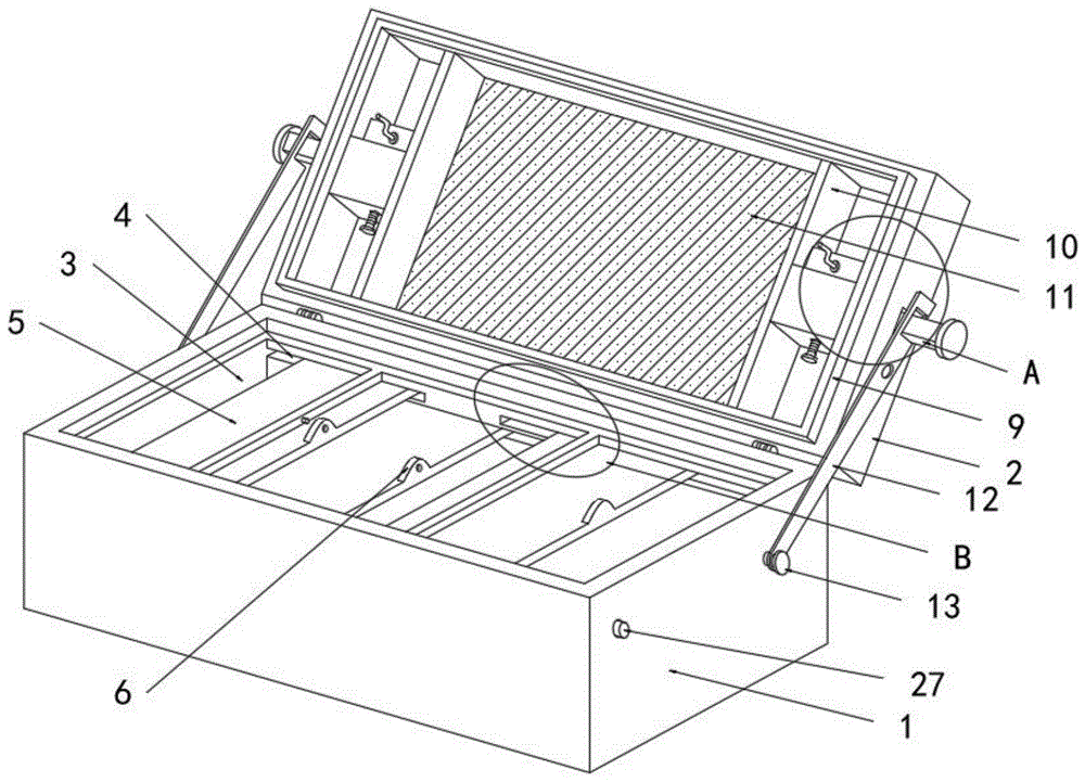
图1为本发明的立体结构示意图;Fig. 1 is the three-dimensional structure schematic diagram of the present invention;
图2为本发明图1中A处的局部放大图;Fig. 2 is the partial enlarged view of place A in Fig. 1 of the present invention;
图3为本发明图1中B处的局部放大图;Fig. 3 is the partial enlarged view of place B in Fig. 1 of the present invention;
图4为本发明连接杆与安装座的结构连接示意图;Fig. 4 is a schematic diagram of the structural connection between the connecting rod and the mounting seat of the present invention;
图5为本发明齿轮与齿条的立体结构示意图。Fig. 5 is a three-dimensional schematic diagram of the gear and the rack of the present invention.
图中:1、工具箱;2、箱盖;3、储放腔室;4、滑槽;5、盖板;6、凸起推块;7、横杆;8、阶梯腔;9、密封垫;10、推板;11、磁性吸附板;12、固定杆;13、固定销;14、安装座;15、连接板;16、手柄;17、连接杆;18、卡腔;19、凸条;20、螺杆;21、活塞板;22、卡块;23、通槽;24、卡槽;25、齿轮;26、齿条;27、定位凸起。In the figure: 1. tool box; 2. box cover; 3. storage chamber; 4. chute; 5. cover plate; 6. protruding push block; 7. cross bar; Pad; 10, push plate; 11, magnetic adsorption plate; 12, fixed rod; 13, fixed pin; 14, mounting seat; 15, connecting plate; 16, handle; 17, connecting rod; 18, card cavity; 20, screw rod; 21, piston plate; 22, block; 23, through groove; 24, draw-in groove; 25, gear; 26, rack; 27, positioning protrusion.
具体实施方式Detailed ways
为了使本发明实现的技术手段、创作特征、达成目的与功效易于明白了解,下面结合具体实施例,进一步阐述本发明,但下述实施例仅仅为本发明的优选实施例,并非全部。基于实施方式中的实施例,本领域技术人员在没有做出创造性劳动的前提下所获得其它实施例,都属于本发明的保护范围。下述实施例中的实验方法,如无特殊说明,均为常规方法,下述实施例中所用的材料、试剂等,如无特殊说明,均可从商业途径得到。In order to make the technical means, creative features, goals and effects achieved by the present invention easy to understand, the present invention will be further elaborated below in conjunction with specific embodiments, but the following embodiments are only preferred embodiments of the present invention, not all. Based on the examples in the implementation manners, other examples obtained by those skilled in the art without making creative efforts all belong to the protection scope of the present invention. The experimental methods in the following examples, unless otherwise specified, are conventional methods, and the materials, reagents, etc. used in the following examples, unless otherwise specified, can be obtained from commercial sources.
实施例:Example:
请参阅图1-图5所示,本发明提供了一种儿童益智辅助教育,包括工具箱1,工具箱1的顶端一侧转动连接有箱盖2,箱盖2的表面安装有密封垫9,且箱盖2的内部设置有拼图使用的磁性吸附板11,箱盖2的内部对称安装有两个可调节距离的推板10,推板10的表面固定连接有连接杆17,箱盖2的内壁表面靠近推板10的一侧设置有空心结构的安装座14,安装座14的一端表面固定连接有连接板15,且安装座14的侧面设有用于连接杆17穿过的通槽23,连接板15的底面与通槽23的顶面齐平,连接板15上设置有用于驱动连接杆17运动的调节机构。Please refer to Fig. 1-shown in Fig. 5, the present invention provides a kind of children's educational auxiliary education, comprise
调节机构调节相邻两个推板10之间的距离,进而使得磁性吸附板11的长度发生改变,可适应不同尺寸的拼图使用,使用范围更广。The adjustment mechanism adjusts the distance between two
调节机构包括转动安装在连接板15表面上的手柄16,连接板15的底部设置有与箱盖2表面转动相连的齿轮25,齿轮25的轴端与手柄16的端部固定;调节机构还包括安装在连接杆17表面上的齿条26,齿条26与齿轮25啮合传动,通过齿轮25与齿条26的啮合,实现齿条26以及连接杆17的传动。The adjustment mechanism includes a
安装座14远离连接板15的表面上螺纹连接有螺杆20,螺杆20的端部转动连接有活塞板21,活塞板21与安装座14内的空腔接触,活塞板21的表面安装有卡块22,连接杆17远离齿条26的表面设有多个卡槽24,卡槽24与卡块22配合使用。Mounting
在调节操作时,活塞板21和卡块22位于安装座14内的空腔中,由于手柄16与齿轮25的轴端固定,而齿轮25又与箱盖2表面转动,拨动手柄16,由手柄16带动着齿轮25转动,齿轮25与齿条26发生啮合,进而使得齿条26发生运动,齿条26带动着连接杆17在通槽23中活动,而连接杆17带动着推板10运动,使得推板10离开其与安装座14相贴合的位置,安装座14的顶面设置为透明形状,便于查看卡槽24与卡块22的卡合位置,当调节好两个推板10的距离后,拨动螺杆20,螺杆20与安装座14表面螺纹转动,并带动着活塞板21在安装座14的空腔中运动,由于活塞板21与空腔贴合,避免活塞板21出现偏移,活塞板21带动着卡块22进入到适配的卡槽24中,实现对连接杆17的固定,从而使得两个推板10之间的距离得到限制调节,根据使用者的拼图需要,可调节不同的长度距离,满足不同拼图尺寸的需求。During the adjustment operation, the
工具箱1的内腔顶部设置有阶梯腔8,阶梯腔8与密封垫9配合使用,工具箱1的内腔位于阶梯腔8的底部安装有两个横杆7。The top of the inner chamber of the
工具箱1的内部设置有三个储放腔室3,每个储放腔室3的内壁均设有滑槽4,储放腔室3的内部安装有与滑槽4滑动相连的盖板5,盖板5的顶面安装有凸起推块6,凸起推块6的表面设有定位孔,横杆7的表面设有与定位孔配合使用的定位柱。The inside of the
在使用时,三种不同尺寸的拼图工具块分别装在三个储放腔室3内,并由盖板5对对应的储放腔室3封闭,在封闭时,盖板5顶面的凸起推块6的表面与横杆7的侧面贴合,凸起推块6表面的定位孔与横杆7上的定位柱正好卡合,实现盖板5的固定,打开时,盖板5可在滑槽4中滑动打开,便于取出三个储放腔室3内的拼图工具,其中拼图工具与磁性吸附板11吸附连接。When in use, jigsaw puzzle tool pieces of three different sizes are installed in three
工具箱1顶部两侧表面均固定安装有固定销13,每个固定销13的外表面转动连接有固定杆12,固定销13的一侧水平设置有定位凸起27,固定杆12的顶部设有与连接杆17配合使用的卡腔18,且固定杆12的表面设有与定位凸起27配合使用的定位槽,卡腔18的内腔底部设置有凸条19,凸条19与连接杆17的表面接触。
初始状态下,工具箱1与箱盖2处于关闭状态,固定杆12上的定位槽与定位凸起27配合使用,即定位凸起27卡入到定位槽内,定位凸起27装在工具箱1的侧壁上,定位凸起27的使用为本领域的成熟技术,使用时,按动定位凸起27,固定杆12失去限制作用,箱盖2与工具箱1发生转动,工具箱1打开后,将固定杆12转动至连接杆17的位置,连接杆17进入到卡腔18中,并与凸条19的表面接触,由凸条19对连接杆17阻挡限位,进而对箱盖2的角度限制,便于使用箱盖2内的磁性吸附板11进行拼图。In the initial state, the
本发明在使用时,由手柄16带动着齿轮25转动,齿轮25与齿条26发生啮合,进而使得齿条26发生运动,齿条26带动着连接杆17在通槽23中活动,而连接杆17带动着推板10运动,使得推板10离开其与安装座14相贴合的位置,安装座14的顶面设置为透明形状,便于查看卡槽24与卡块22的卡合位置,当调节好两个推板10的距离后,拨动螺杆20,螺杆20与安装座14表面螺纹转动,并带动着活塞板21在安装座14的空腔中运动,由于活塞板21与空腔贴合,避免活塞板21出现偏移,活塞板21带动着卡块22进入到适配的卡槽24中,实现对连接杆17的固定,从而使得两个推板10之间的距离得到限制调节,根据使用者的拼图需要,可调节不同的长度距离,满足不同拼图尺寸的需求;When the present invention is in use, the
三种不同尺寸的拼图工具块分别装在三个储放腔室3内,并由盖板5对对应的储放腔室3封闭,在封闭时,盖板5顶面的凸起推块6的表面与横杆7的侧面贴合,凸起推块6表面的定位孔与横杆7上的定位柱正好卡合,实现盖板5的固定,打开时,盖板5可在滑槽4中滑动打开,便于取出三个储放腔室3内的拼图工具;Jigsaw puzzle pieces of three different sizes are installed in three
箱盖2与工具箱1发生转动,工具箱1打开后,将固定杆12转动至连接杆17的位置,连接杆17进入到卡腔18中,并与凸条19的表面接触,由凸条19对连接杆17阻挡限位,进而对箱盖2的角度限制,便于使用箱盖2内的磁性吸附板11进行拼图。
在本发明中,除非另有明确的规定和限定,第一特征在第二特征之“上”或之“下”可以包括第一和第二特征直接接触,也可以包括第一和第二特征不是直接接触而是通过它们之间的另外的特征接触。而且,第一特征在第二特征“之上”、“上方”和“上面”包括第一特征在第二特征正上方和斜上方,或仅仅表示第一特征水平高度高于第二特征。第一特征在第二特征“之下”、“下方”和“下面”包括第一特征在第二特征正下方和斜下方,或仅仅表示第一特征水平高度小于第二特征。In the present invention, unless otherwise clearly specified and limited, a first feature being "on" or "under" a second feature may include direct contact between the first and second features, and may also include the first and second features Not in direct contact but through another characteristic contact between them. Moreover, "above", "above" and "above" the first feature on the second feature include that the first feature is directly above and obliquely above the second feature, or simply means that the first feature is horizontally higher than the second feature. "Below", "beneath" and "under" the first feature to the second feature include that the first feature is directly below and obliquely below the second feature, or simply means that the first feature has a lower level than the second feature.
以上显示和描述了本发明的基本原理、主要特征和本发明的优点。本行业的技术人员应该了解,本发明不受上述实施例的限制,上述实施例和说明书中描述的仅为本发明的优选例,并不用来限制本发明,在不脱离本发明精神和范围的前提下,本发明还会有各种变化和改进,这些变化和改进都落入要求保护的本发明范围内。本发明要求保护范围由所附的权利要求书及其等效物界定。The basic principles, main features and advantages of the present invention have been shown and described above. Those skilled in the art should understand that the present invention is not limited by the above-mentioned embodiments, and those described in the above-mentioned embodiments and description are only preferred examples of the present invention, and are not intended to limit the present invention, without departing from the spirit and scope of the present invention. Under the premise, the present invention will also have various changes and improvements, and these changes and improvements all fall within the scope of the claimed invention. The protection scope of the present invention is defined by the appended claims and their equivalents.
Claims (7)
Priority Applications (1)
| Application Number | Priority Date | Filing Date | Title |
|---|---|---|---|
| CN202210659902.0A CN115294810A (en) | 2022-06-13 | 2022-06-13 | Children benefit supplementary education of intelligence |
Applications Claiming Priority (1)
| Application Number | Priority Date | Filing Date | Title |
|---|---|---|---|
| CN202210659902.0A CN115294810A (en) | 2022-06-13 | 2022-06-13 | Children benefit supplementary education of intelligence |
Publications (1)
| Publication Number | Publication Date |
|---|---|
| CN115294810A true CN115294810A (en) | 2022-11-04 |
Family
ID=83819520
Family Applications (1)
| Application Number | Title | Priority Date | Filing Date |
|---|---|---|---|
| CN202210659902.0A Pending CN115294810A (en) | 2022-06-13 | 2022-06-13 | Children benefit supplementary education of intelligence |
Country Status (1)
| Country | Link |
|---|---|
| CN (1) | CN115294810A (en) |
Cited By (1)
| Publication number | Priority date | Publication date | Assignee | Title |
|---|---|---|---|---|
| CN118179006A (en) * | 2024-05-14 | 2024-06-14 | 汕头市茂园塑胶有限公司 | Educational jigsaw puzzle |
Citations (9)
| Publication number | Priority date | Publication date | Assignee | Title |
|---|---|---|---|---|
| US5980354A (en) * | 1998-05-04 | 1999-11-09 | Prest; Jed | Storyboard toys for nurturing cognition and learning strategies |
| CN106157748A (en) * | 2016-08-26 | 2016-11-23 | 成都多元智能文化传播有限公司 | A kind of child educates utensil with Fructus Alpiniae Oxyphyllae |
| CN210466905U (en) * | 2019-06-01 | 2020-05-05 | 济宁职业技术学院 | Preschool education educational die |
| CN212032478U (en) * | 2020-04-19 | 2020-11-27 | 付宗亮 | Economic teaching simulation sand table |
| CN214428235U (en) * | 2021-04-07 | 2021-10-19 | 山东科技大学 | A portable sand table for civil engineering management |
| CN214587337U (en) * | 2021-03-01 | 2021-11-02 | 长垣烹饪职业技术学院 | Distance education device for education and training |
| CN214759743U (en) * | 2021-02-02 | 2021-11-19 | 李然 | High-efficient computer teaching is equipped with device |
| CN215007185U (en) * | 2021-06-19 | 2021-12-03 | 杭州泰瓯模型有限公司 | Model display device that city planning field was used |
| CN215018690U (en) * | 2021-07-12 | 2021-12-07 | 王雪莹 | Breathe nursing puncture auxiliary device |
-
2022
- 2022-06-13 CN CN202210659902.0A patent/CN115294810A/en active Pending
Patent Citations (9)
| Publication number | Priority date | Publication date | Assignee | Title |
|---|---|---|---|---|
| US5980354A (en) * | 1998-05-04 | 1999-11-09 | Prest; Jed | Storyboard toys for nurturing cognition and learning strategies |
| CN106157748A (en) * | 2016-08-26 | 2016-11-23 | 成都多元智能文化传播有限公司 | A kind of child educates utensil with Fructus Alpiniae Oxyphyllae |
| CN210466905U (en) * | 2019-06-01 | 2020-05-05 | 济宁职业技术学院 | Preschool education educational die |
| CN212032478U (en) * | 2020-04-19 | 2020-11-27 | 付宗亮 | Economic teaching simulation sand table |
| CN214759743U (en) * | 2021-02-02 | 2021-11-19 | 李然 | High-efficient computer teaching is equipped with device |
| CN214587337U (en) * | 2021-03-01 | 2021-11-02 | 长垣烹饪职业技术学院 | Distance education device for education and training |
| CN214428235U (en) * | 2021-04-07 | 2021-10-19 | 山东科技大学 | A portable sand table for civil engineering management |
| CN215007185U (en) * | 2021-06-19 | 2021-12-03 | 杭州泰瓯模型有限公司 | Model display device that city planning field was used |
| CN215018690U (en) * | 2021-07-12 | 2021-12-07 | 王雪莹 | Breathe nursing puncture auxiliary device |
Cited By (2)
| Publication number | Priority date | Publication date | Assignee | Title |
|---|---|---|---|---|
| CN118179006A (en) * | 2024-05-14 | 2024-06-14 | 汕头市茂园塑胶有限公司 | Educational jigsaw puzzle |
| CN118179006B (en) * | 2024-05-14 | 2024-07-05 | 汕头市茂园塑胶有限公司 | Educational jigsaw puzzle |
Similar Documents
| Publication | Publication Date | Title |
|---|---|---|
| CN210295465U (en) | Intelligent teaching device based on internet | |
| CN214340815U (en) | Multimedia Podium Table with Sliding Doors | |
| CN216388377U (en) | Portable note jigsaw block for teaching music teachers in vocational schools | |
| CN209962476U (en) | A information display device for real teaching of instructing of international trade | |
| CN209560775U (en) | A kind of etiquette teaching Special teaching frame | |
| CN216352941U (en) | Accounting book display device for accounting classroom | |
| CN211319531U (en) | Mathematical statistics presentation device | |
| CN214405405U (en) | A learning device suitable for teaching software development and teaching | |
| CN109697893B (en) | Teaching device capable of comparing differences between traditional Chinese and western aerobics exercises | |
| CN223063527U (en) | A kind of hanging liquid crystal television | |
| CN210223106U (en) | Teaching equipment based on holographic projection | |
| CN219891870U (en) | A multifunctional display board | |
| CN215298607U (en) | A demonstration device for the effect of lens on light for university physics experiments | |
| CN210297841U (en) | Combined broadcast directing keyboard | |
| CN221023081U (en) | A drawing framework for realizing the four-line positioning method of painting | |
| CN220543471U (en) | A push-pull electronic blackboard | |
| CN215933108U (en) | Advertisement fan capable of switching different advertisement surfaces | |
| CN220933629U (en) | A display teaching aid for interacting with young children | |
| CN219267173U (en) | A show sand table for teaching | |
| CN223380221U (en) | Desktop jack type small building block | |
| CN221769548U (en) | A field computer teaching device | |
| CN210244716U (en) | An interesting interactive teaching device in the classroom | |
| CN219738391U (en) | A display model for architectural teaching | |
| CN220923656U (en) | Push-pull writing board capable of realizing synchronous displacement, reset and movement | |
| CN215450553U (en) | Color mixing teaching platform |
Legal Events
| Date | Code | Title | Description |
|---|---|---|---|
| PB01 | Publication | ||
| PB01 | Publication | ||
| SE01 | Entry into force of request for substantive examination | ||
| SE01 | Entry into force of request for substantive examination | ||
| RJ01 | Rejection of invention patent application after publication | ||
| RJ01 | Rejection of invention patent application after publication |
Application publication date: 20221104 |