CN115261663B - Gold alloy bonding wire and preparation method thereof - Google Patents
Gold alloy bonding wire and preparation method thereof Download PDFInfo
- Publication number
- CN115261663B CN115261663B CN202210914551.3A CN202210914551A CN115261663B CN 115261663 B CN115261663 B CN 115261663B CN 202210914551 A CN202210914551 A CN 202210914551A CN 115261663 B CN115261663 B CN 115261663B
- Authority
- CN
- China
- Prior art keywords
- wall
- alloy
- bonding wire
- gear
- tube
- Prior art date
- Legal status (The legal status is an assumption and is not a legal conclusion. Google has not performed a legal analysis and makes no representation as to the accuracy of the status listed.)
- Active
Links
- 238000002360 preparation method Methods 0.000 title claims abstract description 14
- 229910001020 Au alloy Inorganic materials 0.000 title claims description 28
- 239000003353 gold alloy Substances 0.000 title claims description 28
- 229910045601 alloy Inorganic materials 0.000 claims abstract description 121
- 239000000956 alloy Substances 0.000 claims abstract description 121
- 238000002425 crystallisation Methods 0.000 claims description 92
- 230000008025 crystallization Effects 0.000 claims description 92
- 238000007789 sealing Methods 0.000 claims description 80
- XLYOFNOQVPJJNP-UHFFFAOYSA-N water Substances O XLYOFNOQVPJJNP-UHFFFAOYSA-N 0.000 claims description 48
- OKTJSMMVPCPJKN-UHFFFAOYSA-N Carbon Chemical compound [C] OKTJSMMVPCPJKN-UHFFFAOYSA-N 0.000 claims description 38
- 229910002804 graphite Inorganic materials 0.000 claims description 38
- 239000010439 graphite Substances 0.000 claims description 38
- 238000003723 Smelting Methods 0.000 claims description 36
- 239000007788 liquid Substances 0.000 claims description 36
- 239000010935 stainless steel Substances 0.000 claims description 34
- 229910001220 stainless steel Inorganic materials 0.000 claims description 34
- 238000007599 discharging Methods 0.000 claims description 33
- XKRFYHLGVUSROY-UHFFFAOYSA-N Argon Chemical compound [Ar] XKRFYHLGVUSROY-UHFFFAOYSA-N 0.000 claims description 30
- 238000000034 method Methods 0.000 claims description 29
- RYGMFSIKBFXOCR-UHFFFAOYSA-N Copper Chemical compound [Cu] RYGMFSIKBFXOCR-UHFFFAOYSA-N 0.000 claims description 23
- 238000000137 annealing Methods 0.000 claims description 23
- 229910052802 copper Inorganic materials 0.000 claims description 23
- 239000010949 copper Substances 0.000 claims description 23
- 239000000110 cooling liquid Substances 0.000 claims description 21
- 238000003860 storage Methods 0.000 claims description 21
- 238000005266 casting Methods 0.000 claims description 20
- 230000035939 shock Effects 0.000 claims description 20
- 238000004140 cleaning Methods 0.000 claims description 19
- PXHVJJICTQNCMI-UHFFFAOYSA-N Nickel Chemical compound [Ni] PXHVJJICTQNCMI-UHFFFAOYSA-N 0.000 claims description 18
- 238000004804 winding Methods 0.000 claims description 18
- 230000008569 process Effects 0.000 claims description 16
- 229910052786 argon Inorganic materials 0.000 claims description 15
- 238000006243 chemical reaction Methods 0.000 claims description 15
- 238000001816 cooling Methods 0.000 claims description 13
- 230000006698 induction Effects 0.000 claims description 13
- KDLHZDBZIXYQEI-UHFFFAOYSA-N Palladium Chemical compound [Pd] KDLHZDBZIXYQEI-UHFFFAOYSA-N 0.000 claims description 12
- 238000010521 absorption reaction Methods 0.000 claims description 11
- 230000000670 limiting effect Effects 0.000 claims description 11
- 239000002994 raw material Substances 0.000 claims description 11
- 238000010438 heat treatment Methods 0.000 claims description 10
- 239000013078 crystal Substances 0.000 claims description 9
- 229910052759 nickel Inorganic materials 0.000 claims description 9
- 239000011265 semifinished product Substances 0.000 claims description 9
- 238000010992 reflux Methods 0.000 claims description 8
- 239000004576 sand Substances 0.000 claims description 8
- 238000007711 solidification Methods 0.000 claims description 8
- 230000008023 solidification Effects 0.000 claims description 8
- 238000012546 transfer Methods 0.000 claims description 8
- 239000000463 material Substances 0.000 claims description 7
- OYPRJOBELJOOCE-UHFFFAOYSA-N Calcium Chemical compound [Ca] OYPRJOBELJOOCE-UHFFFAOYSA-N 0.000 claims description 6
- 229910052684 Cerium Inorganic materials 0.000 claims description 6
- BQCADISMDOOEFD-UHFFFAOYSA-N Silver Chemical compound [Ag] BQCADISMDOOEFD-UHFFFAOYSA-N 0.000 claims description 6
- 229910052791 calcium Inorganic materials 0.000 claims description 6
- 239000011575 calcium Substances 0.000 claims description 6
- GWXLDORMOJMVQZ-UHFFFAOYSA-N cerium Chemical compound [Ce] GWXLDORMOJMVQZ-UHFFFAOYSA-N 0.000 claims description 6
- PCHJSUWPFVWCPO-UHFFFAOYSA-N gold Chemical compound [Au] PCHJSUWPFVWCPO-UHFFFAOYSA-N 0.000 claims description 6
- 229910052737 gold Inorganic materials 0.000 claims description 6
- 239000010931 gold Substances 0.000 claims description 6
- 229910052763 palladium Inorganic materials 0.000 claims description 6
- 229910052709 silver Inorganic materials 0.000 claims description 6
- 239000004332 silver Substances 0.000 claims description 6
- 238000003756 stirring Methods 0.000 claims description 6
- 238000005491 wire drawing Methods 0.000 claims description 6
- 239000007789 gas Substances 0.000 claims description 4
- 238000005303 weighing Methods 0.000 claims description 4
- 239000000654 additive Substances 0.000 claims description 3
- 230000000996 additive effect Effects 0.000 claims description 3
- 239000000155 melt Substances 0.000 claims description 3
- 239000007769 metal material Substances 0.000 claims description 3
- 238000007670 refining Methods 0.000 claims description 3
- 238000002844 melting Methods 0.000 claims description 2
- 230000008018 melting Effects 0.000 claims description 2
- PEDCQBHIVMGVHV-UHFFFAOYSA-N Glycerine Chemical compound OCC(O)CO PEDCQBHIVMGVHV-UHFFFAOYSA-N 0.000 claims 3
- 238000007664 blowing Methods 0.000 claims 3
- 230000000694 effects Effects 0.000 description 7
- 238000009434 installation Methods 0.000 description 7
- 230000005540 biological transmission Effects 0.000 description 6
- 238000010586 diagram Methods 0.000 description 6
- 238000002156 mixing Methods 0.000 description 6
- 239000004020 conductor Substances 0.000 description 5
- 239000000498 cooling water Substances 0.000 description 4
- 238000004519 manufacturing process Methods 0.000 description 2
- 229910052751 metal Inorganic materials 0.000 description 2
- 239000002184 metal Substances 0.000 description 2
- 238000012986 modification Methods 0.000 description 2
- 230000004048 modification Effects 0.000 description 2
- 238000005498 polishing Methods 0.000 description 2
- 229910001208 Crucible steel Inorganic materials 0.000 description 1
- 230000009471 action Effects 0.000 description 1
- PNEYBMLMFCGWSK-UHFFFAOYSA-N aluminium oxide Inorganic materials [O-2].[O-2].[O-2].[Al+3].[Al+3] PNEYBMLMFCGWSK-UHFFFAOYSA-N 0.000 description 1
- 230000009286 beneficial effect Effects 0.000 description 1
- 239000000919 ceramic Substances 0.000 description 1
- 238000010276 construction Methods 0.000 description 1
- 238000009749 continuous casting Methods 0.000 description 1
- 230000007547 defect Effects 0.000 description 1
- 238000011161 development Methods 0.000 description 1
- 238000006073 displacement reaction Methods 0.000 description 1
- 230000005674 electromagnetic induction Effects 0.000 description 1
- 230000002708 enhancing effect Effects 0.000 description 1
- 230000004907 flux Effects 0.000 description 1
- 229910001004 magnetic alloy Inorganic materials 0.000 description 1
- 239000011553 magnetic fluid Substances 0.000 description 1
- 230000005389 magnetism Effects 0.000 description 1
- 230000007246 mechanism Effects 0.000 description 1
- 238000000465 moulding Methods 0.000 description 1
- 238000004806 packaging method and process Methods 0.000 description 1
- 238000012545 processing Methods 0.000 description 1
- 239000000047 product Substances 0.000 description 1
- 239000000758 substrate Substances 0.000 description 1
- 239000002912 waste gas Substances 0.000 description 1
Images


Classifications
-
- C—CHEMISTRY; METALLURGY
- C22—METALLURGY; FERROUS OR NON-FERROUS ALLOYS; TREATMENT OF ALLOYS OR NON-FERROUS METALS
- C22C—ALLOYS
- C22C5/00—Alloys based on noble metals
- C22C5/02—Alloys based on gold
-
- B—PERFORMING OPERATIONS; TRANSPORTING
- B22—CASTING; POWDER METALLURGY
- B22D—CASTING OF METALS; CASTING OF OTHER SUBSTANCES BY THE SAME PROCESSES OR DEVICES
- B22D11/00—Continuous casting of metals, i.e. casting in indefinite lengths
- B22D11/001—Continuous casting of metals, i.e. casting in indefinite lengths of specific alloys
-
- B—PERFORMING OPERATIONS; TRANSPORTING
- B22—CASTING; POWDER METALLURGY
- B22D—CASTING OF METALS; CASTING OF OTHER SUBSTANCES BY THE SAME PROCESSES OR DEVICES
- B22D11/00—Continuous casting of metals, i.e. casting in indefinite lengths
- B22D11/04—Continuous casting of metals, i.e. casting in indefinite lengths into open-ended moulds
- B22D11/055—Cooling the moulds
-
- B—PERFORMING OPERATIONS; TRANSPORTING
- B22—CASTING; POWDER METALLURGY
- B22D—CASTING OF METALS; CASTING OF OTHER SUBSTANCES BY THE SAME PROCESSES OR DEVICES
- B22D11/00—Continuous casting of metals, i.e. casting in indefinite lengths
- B22D11/10—Supplying or treating molten metal
- B22D11/11—Treating the molten metal
- B22D11/114—Treating the molten metal by using agitating or vibrating means
- B22D11/115—Treating the molten metal by using agitating or vibrating means by using magnetic fields
-
- B—PERFORMING OPERATIONS; TRANSPORTING
- B22—CASTING; POWDER METALLURGY
- B22D—CASTING OF METALS; CASTING OF OTHER SUBSTANCES BY THE SAME PROCESSES OR DEVICES
- B22D11/00—Continuous casting of metals, i.e. casting in indefinite lengths
- B22D11/12—Accessories for subsequent treating or working cast stock in situ
- B22D11/124—Accessories for subsequent treating or working cast stock in situ for cooling
- B22D11/1248—Means for removing cooling agent from the surface of the cast stock
-
- B—PERFORMING OPERATIONS; TRANSPORTING
- B22—CASTING; POWDER METALLURGY
- B22D—CASTING OF METALS; CASTING OF OTHER SUBSTANCES BY THE SAME PROCESSES OR DEVICES
- B22D11/00—Continuous casting of metals, i.e. casting in indefinite lengths
- B22D11/14—Plants for continuous casting
- B22D11/141—Plants for continuous casting for vertical casting
-
- C—CHEMISTRY; METALLURGY
- C22—METALLURGY; FERROUS OR NON-FERROUS ALLOYS; TREATMENT OF ALLOYS OR NON-FERROUS METALS
- C22C—ALLOYS
- C22C1/00—Making non-ferrous alloys
- C22C1/02—Making non-ferrous alloys by melting
-
- C—CHEMISTRY; METALLURGY
- C22—METALLURGY; FERROUS OR NON-FERROUS ALLOYS; TREATMENT OF ALLOYS OR NON-FERROUS METALS
- C22C—ALLOYS
- C22C30/00—Alloys containing less than 50% by weight of each constituent
-
- C—CHEMISTRY; METALLURGY
- C22—METALLURGY; FERROUS OR NON-FERROUS ALLOYS; TREATMENT OF ALLOYS OR NON-FERROUS METALS
- C22F—CHANGING THE PHYSICAL STRUCTURE OF NON-FERROUS METALS AND NON-FERROUS ALLOYS
- C22F1/00—Changing the physical structure of non-ferrous metals or alloys by heat treatment or by hot or cold working
- C22F1/02—Changing the physical structure of non-ferrous metals or alloys by heat treatment or by hot or cold working in inert or controlled atmosphere or vacuum
-
- C—CHEMISTRY; METALLURGY
- C22—METALLURGY; FERROUS OR NON-FERROUS ALLOYS; TREATMENT OF ALLOYS OR NON-FERROUS METALS
- C22F—CHANGING THE PHYSICAL STRUCTURE OF NON-FERROUS METALS AND NON-FERROUS ALLOYS
- C22F1/00—Changing the physical structure of non-ferrous metals or alloys by heat treatment or by hot or cold working
- C22F1/14—Changing the physical structure of non-ferrous metals or alloys by heat treatment or by hot or cold working of noble metals or alloys based thereon
Landscapes
- Chemical & Material Sciences (AREA)
- Engineering & Computer Science (AREA)
- Mechanical Engineering (AREA)
- Materials Engineering (AREA)
- Metallurgy (AREA)
- Organic Chemistry (AREA)
- Physics & Mathematics (AREA)
- Thermal Sciences (AREA)
- Crystallography & Structural Chemistry (AREA)
- Manufacture And Refinement Of Metals (AREA)
Abstract
The invention discloses a bonding wire of alloy and a preparation method thereof, which belong to the technical field of bonding wires, and concretely relates to a bonding wire of alloy and a preparation method thereof.
Description
Technical Field
The invention relates to the technical field of bonding wires, in particular to a gold alloy bonding wire and a preparation method thereof.
Background
The bonding wire is a main connection mode for connecting the chip and an external packaging substrate or a multilayer circuit board, and the development trend of the bonding wire is mainly in the aspects of miniaturization of wire diameter, long service life of workshops and long wire shaft length from the direction of products.
The prior art has the following defects: the existing alloy rod processing engineering is formed by adding various raw materials and mixing, the alloy rod is drawn and cast through a directional continuous casting process, the alloy rod is easily layered due to different densities in the smelting process, so that the molten liquid is unevenly mixed, and the alloy molten liquid is drawn out after being cooled rapidly for a single time, so that poor crystallization compactness, uneven tissue mixing and lower surface glossiness of the drawn alloy rod are caused.
Therefore, it is necessary to invent a gold alloy bonding wire and a method for manufacturing the same.
Disclosure of Invention
Therefore, the invention provides a gold alloy bonding wire and a preparation method thereof, wherein a crucible II and an alloy solution are heated and melted through an intermediate frequency induction coil, after refining, heating is stopped, the melted alloy solution is cooled to room temperature along with a reaction cavity, heating is repeated for 2-3 times, the alloy solution flows into the crucible I through the crucible, an electromagnetic coil stirs the alloy solution in a graphite sleeve, a rodless cylinder drives an outer sleeve to move, the alloy solution is stirred and shaked to deposit through electromagnetic force of a primary crystallization component and a secondary crystallization component, and cooling is carried out on the alloy solution for crystallization in a matching way for multiple times, so that the problems of uneven alloy solution mixing, and improved compactness and uniform structure after alloy crystallization are solved.
In order to achieve the above object, the present invention provides the following technical solutions: the preparation method of the gold alloy bonding wire comprises the following steps of material preparation, alloy smelting, drawing casting, wire drawing, annealing and wire winding:
step one: preparing materials, namely weighing raw materials of the gold alloy bonding wire according to the required weight, wherein the gold alloy bonding wire is composed of metal materials with the following weight ratio of 10-30% of silver, 20-30% of nickel, 0.5-2% of palladium, 5-50ppm of trace additive elements of calcium and 10-200ppm of cerium, and the balance of gold;
step two: alloy smelting and drawing casting, namely smelting raw materials of the gold alloy bonding wire into alloy solution, stirring and vibrating the alloy solution through electromagnetic force, cooling the alloy solution for crystallization by matching with repeated cooling, so that the convection, heat transfer and mass transfer processes of the melt are enhanced, the superheat degree of the alloy solution is improved and eliminated, the equiaxed crystal rate of a casting blank can be improved, the casting blank with good solidification structure is obtained, the solidification of the casting blank is controlled, an alloy rod with the diameter of 5-10mm is formed, and meanwhile, the surface of the alloy rod is erased and polished;
step three: drawing, namely drawing the drawn and cast alloy rod to obtain a bonding wire semi-finished product with the diameter of 0.08-0.5mm through a drawing process, drawing the bonding wire semi-finished product into an alloy wire with the diameter of 0.26mm through a middle drawing device, wherein the elongation of the middle drawing die is 9-18%, the drawing speed is 60-180m/min, and drawing the bonding wire into an alloy bonding wire with the diameter of 25 mu m through a fine drawing and superfine drawing device;
Step four: annealing, namely carrying out intermediate annealing on the bonding wire semi-finished product for a plurality of times in the wire drawing process, wherein N2 is adopted as annealing atmosphere in the annealing process, the effective length of the annealing furnace is 600-1000mm, the annealing temperature is 600-800 ℃, and the annealing speed is 40-80m/min;
step five: and (3) winding, namely placing the qualified gold alloy bonding wire on a rewinder for winding, wherein the winding tension is 6-35g, and the winding speed is 400-650rpm.
Preferably, the equipment in the second step comprises a supporting frame, a smelting device, a bonding wire crystallization device and a cleaning device, wherein the smelting device is arranged at the top of the supporting frame, a hanging bracket is fixedly arranged at the bottom of the supporting frame, the bonding wire crystallization device is arranged at the top of the hanging bracket, the top of the bonding wire crystallization device is connected with the bottom of the smelting device, the cleaning device is arranged at the bottom of the bonding wire crystallization device, the cleaning device comprises a shell, annular holes are formed in the top and the bottom of the shell, and the central shafts of the smelting device, the bonding wire crystallization device and the cleaning device are mutually perpendicular;
the smelting device comprises a base, wherein the base is fixedly arranged on the inner wall of the top of a supporting frame, a limit groove is formed in the inner wall of the base, a liquid outlet nozzle is formed in the bottom of the inner wall of the limit groove, a bottom lining ring is arranged at the top of the base, a supporting tube is arranged at the top of the bottom lining ring, a top lining ring is arranged at the top of the supporting tube, crescent plates are fixedly arranged at two sides of the bottom lining ring and the top lining ring, concave surfaces are formed in the supporting tube and the outer wall of the base, the top and the bottom of the bottom lining ring are respectively connected with the supporting tube and the base through crescent plate grafting concave surfaces, and the top lining ring is arranged at the top of the supporting tube through crescent plate grafting concave surfaces;
Clamping grooves are formed in two sides of the tops of the top lining ring and the bottom lining ring, a first crucible is arranged on the inner wall of the bottom lining ring, a second crucible is arranged on the inner wall of the top lining ring, a first liquid outlet and a second liquid outlet are formed in the bottoms of the first crucible and the second crucible respectively, semi-convex rings are fixedly arranged on two sides of the tops of the first crucible and the second crucible respectively, the first crucible and the crucible are respectively arranged on the inner wall of the bottom lining ring and the inner wall of the top lining ring through semi-convex ring inserting clamping grooves, the bottoms of the second crucible are arranged on the inner wall of a supporting tube, an intermediate frequency induction coil is fixedly arranged on the inner wall of the supporting tube, the intermediate frequency induction coil is not in contact with the second crucible, the bottoms of the first crucible are inserted into the inner wall of the limiting grooves and are in sealing connection with the inner wall of the base, the bottom of the liquid outlet is connected with the liquid outlet, the smelting device comprises a sealing cylinder, the sealing cylinder is sleeved on the outer walls of the bottom lining ring, the supporting tube, the top lining ring and the outer wall of the base, and the top of the sealing cylinder are welded with the top of the base;
the bonding wire crystallization device comprises a primary crystallization component and a secondary crystallization component, wherein the primary crystallization component and the secondary crystallization component are mutually perpendicular, the primary crystallization component comprises an outer cylinder, a graphite sleeve is fixedly arranged at the inner wall and the bottom of the outer cylinder, the top of the graphite sleeve is mutually parallel to the top of the inner wall of the outer cylinder, a sealing water lantern ring is arranged on the outer wall of the graphite sleeve, connecting rods are fixedly arranged at two sides of the sealing water lantern ring, one side of each connecting rod is fixedly connected with the inner wall of the outer cylinder, the graphite sleeve is not connected with the sealing water lantern ring, an electromagnetic coil is fixedly arranged at the inner wall of the sealing water mantle ring, pipeline interfaces are arranged at two sides of the outer cylinder, two groups of pipeline interfaces are arranged, a sealing flange is fixedly arranged at the top of the outer cylinder, the top of the sealing flange is fixedly connected with the bottom of the base, the top of the graphite sleeve is in sealing connection with the bottom of the liquid outlet nozzle, a half-arc plate is arranged on the outer wall of the bottom of the graphite sleeve, and two groups of half-arc plates are arranged;
The secondary crystallization assembly comprises an outer sleeve, an inner sleeve is fixedly arranged on the inner wall of the outer sleeve, a ring-mounted reflux copper pipe is fixedly arranged on the inner wall of the inner sleeve, two ends of the ring-mounted reflux copper pipe are arranged at the bottom of the inner sleeve, stainless steel pipes are fixedly arranged on the inner wall of the inner sleeve, hanging lugs are fixedly arranged on two sides of the top of each stainless steel pipe, the hanging lugs are inserted between two groups of semi-arc plates, the hanging lugs are in sliding connection with the semi-arc plates, the bottom of each graphite sleeve is inserted into the inner wall of the top of each stainless steel pipe, the graphite sleeve is not contacted with the stainless steel pipes, springs are fixedly arranged at the tops of the two groups of hanging lugs, and the tops of the springs are fixedly connected with the bottom of the outer cylinder;
the bonding wire crystallization device comprises a supporting seat, supporting arms are fixedly arranged at the central positions of two sides of the supporting seat, sliding grooves are formed in one side of the supporting seat, two groups of sliding grooves are formed in the supporting seat, a shock absorption seat is arranged on one side of the supporting seat, crystallization holes are fixedly arranged in the inner wall of the shock absorption seat, the top of each crystallization hole is fixedly connected with the bottom of a stainless steel tube, a sliding block is fixedly arranged on one side of the shock absorption seat, two groups of sliding blocks are arranged, the shock absorption seat is arranged on the outer wall of the supporting seat through a sliding block inserting sliding groove, the shock absorption seat is in sliding connection with the supporting seat, protruding blocks are fixedly arranged on two sides of the shock absorption seat and are mutually perpendicular to the supporting arms, a spring rod is fixedly arranged at the bottom of the protruding blocks, and the bottom of the spring rod is fixedly connected with the top of the supporting arms;
The utility model discloses a quick-change type crystallizer for a waste gas boiler, including supporting seat, crystallization hole, outer tube, hose, pipe input, ring dress backward flow copper pipe output and a set of pipeline interface interconnect, supporting seat one side bottom fixed mounting has the ejection of compact outer tube, ejection of compact outer tube inner wall fixed mounting has ejection of compact inner tube, ejection of compact inner tube and crystallization hole mutually perpendicular, ejection of compact inner tube and ejection of compact outer tube junction fixed mounting have spiral water course, the hose has been seted up to ejection of compact outer tube outer wall, hose input and ejection of compact inner tube and spiral water course outer wall interconnect, hose input and ring dress backward flow copper pipe output and a set of pipeline interface interconnect.
Preferably, the top cover is detachably arranged at the top of the sealing cylinder, a sealing cover is fixedly arranged on one side of the outer wall of the sealing cylinder, the inner wall of the sealing cover is connected with the inner wall of the sealing cylinder, a discharging assembly is arranged on the inner wall of the sealing cover and comprises a C-shaped plate, the right side of the C-shaped plate is fixedly connected with the inner wall of the sealing cover, a screw rod is arranged on one side of the C-shaped plate, two ends of the screw rod are movably connected with the top and the bottom of the C-shaped plate respectively, a limit column is arranged on one side of the screw rod, two ends of the limit column are fixedly connected with the top and the bottom of the C-shaped plate respectively, the discharging assembly comprises a support rod, the screw rod is inserted into the right end of the inner wall of the support rod and is connected with the screw rod in a threaded manner, a motor II is fixedly arranged at the right end of the inner wall of the support rod in a plugging column, the left end of the support rod is arranged on the left end of the sealing cylinder in a sliding manner, and two ends of the support rod are perpendicular to the two liquid outlet.
Preferably, a reaction cavity is arranged between the top of the top lining ring and the inner wall of the sealing cylinder, a vacuum valve is fixedly arranged on one side of the outer wall of the sealing cylinder, an argon valve is fixedly arranged on one side of the outer wall of the sealing cylinder, and the output ends of the vacuum valve and the argon valve are connected with the reaction cavity.
Preferably, the outer tube right side fixed mounting has the sand grip, the sand grip is equipped with two sets of, two sets of the sand grip inner wall is pegged graft there is the gag lever post, gag lever post and sand grip sliding connection, gag lever post top and base bottom fixed connection, outer tube left side fixed mounting has the backup pad, gallows one side fixed mounting has the L template, L template right side fixed mounting has the rodless cylinder, rodless cylinder right side output shaft and backup pad fixed connection, gag lever post bottom and gallows top fixed connection, supporting seat one side and gallows top fixed connection, the guide hole has been seted up to gallows central point put, ejection of compact outer tube is pegged graft at the guide hole inner wall.
Preferably, hanging frame is fixed to the bottom of hanging frame, hanging frame inner wall is equipped with the movable block, the movable block is equipped with two sets of, two sets of movable block one side installs the guide pulley, the hanging frame bottom is equipped with the water storage box, water storage box outer wall and support frame inner wall fixed connection, cleaning device installs between hanging frame and water storage box, shell bottom fixed mounting is at water storage box top, shell inner wall central point puts fixed mounting has the ring gear, the ring gear inner wall is equipped with gear one, gear one is equipped with three sets of, three sets of gear one and ring gear meshing connection, three sets of be equipped with the tooth axle between the gear one, the through-hole has been seted up to tooth axle inner wall, tooth axle bottom fixed mounting has gear two, tooth axle and three sets of gear one meshing connection, gear one top is equipped with the set of triangle-plate, triangle-plate top movable mounting has the pivot, the pivot is equipped with three sets of pivot bottom respectively with three sets of triangle-plate fixed connection, three sets of sponge cover is installed at the top, motor top fixed mounting has gear one, three-set motor inner wall, three-gear inner wall hollow shaft, three-hollow shaft inner tube, three-hollow shaft installation hole installation, three-hollow shaft installation hollow shaft, three-hollow shaft installation hole bottom has.
Preferably, the two groups of moving blocks are movably connected with the inner wall of the hanging frame and symmetrically arranged, the two sides of the hanging frame are fixedly provided with air cylinders, the output shafts of the two groups of air cylinders are respectively fixedly connected with one side of the two groups of moving blocks, one group of moving blocks is fixedly provided with a first motor, and an output shaft of the first motor is fixedly connected with one group of guide wheels.
An alloy bonding wire is prepared by a preparation method of the alloy bonding wire.
The beneficial effects of the invention are as follows:
1. heating the crucible II and the alloy solution through the medium-frequency induction coil to completely melt the alloy, refining for 10-20 minutes, stopping heating, cooling the melted alloy solution to room temperature along with the reaction cavity, repeatedly heating for 2-3 times, enabling the alloy solution to flow into the crucible I through a liquid outlet of the crucible II, stirring the alloy solution in the graphite sleeve through the electromagnetic coil, enabling the alloy solution to perform primary crystallization, enabling the rodless cylinder to drive the outer sleeve to move up and down, driving the stainless steel pipe to vibrate while moving up and down, enabling the alloy solution to be tightly deposited in the stainless steel pipe for secondary crystallization, enabling the alloy solution subjected to secondary crystallization to be deposited on the top of the traction rod, enabling the traction rod to drive the alloy solution continuously subjected to secondary crystallization to move downwards through the guide wheel, continuously pulling out through the discharging inner pipe to form an alloy rod, and cooling the alloy solution for crystallization for a plurality of times through electromagnetic force of the primary crystallization component and the secondary crystallization component, thereby enhancing convection, heat transfer and mass transfer processes of the alloy solution, obtaining a casting blank with good solidification structure, controlling the casting blank, and uniformly mixing the alloy solution, and improving the uniformity and tissue solidification effects of the alloy blank after the alloy crystallization;
2. The cooling liquid is input into the outer cylinder through the pipeline interface, the graphite sleeve is cooled, alloy melt is subjected to primary crystallization, the alloy melt after the primary crystallization flows into the stainless steel pipe, the cooling liquid is conveyed into the annular backflow copper pipe, the stainless steel pipe is subjected to secondary cooling through the inner sleeve, the alloy melt is tightly deposited in the stainless steel pipe for secondary crystallization, meanwhile, the cooling liquid conveyed out by the annular backflow copper pipe and the output end of the pipeline interface flows into the hose and flows into the spiral water channel of the discharging outer pipe through the hose, the outer wall of the discharging inner pipe is cooled, the cooling liquid flows out of the bottom of the discharging outer pipe through the spiral water channel and is sprayed on the surface of the alloy rod, and flows into the water storage box through the shell, so that the alloy melt is crystallized at different temperatures, the superheat degree of the alloy solution is improved, and the equiaxial crystal rate of casting blanks is improved;
3. the alloy rod is pulled into the shell through the traction rod, the alloy rod sequentially passes through the hollow tube and the inside of the through hole and is pulled out through the annular hole, the motor III drives the gear III to rotate, the gear III drives the gear II to rotate, the gear II drives the gear shaft, the gear shaft drives the gear I of the three groups, the gear I is meshed with the inner gear ring, the gear I of the three groups revolves around the gear shaft while rotating in the inner gear ring, so that the sponge sleeve rotates and revolves, the three groups of sponge sleeves erase and polish the cooling liquid on the surface of the alloy rod, and the effects of erasing the cooling liquid, polishing the surface of the alloy rod and improving the glossiness are achieved.
Drawings
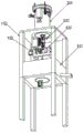
FIG. 1 is a schematic elevational view of the present invention;
FIG. 2 is a schematic view of the installation structure of the water storage box of the present invention;
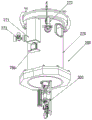
FIG. 3 is a schematic diagram of the installation structure of the bonding wire crystallization device according to the present invention;
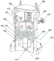
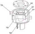
FIG. 4 is a schematic cross-sectional view of a smelting apparatus of the present invention;
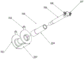
FIG. 5 is an exploded view of the smelting apparatus of the present invention;
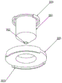
FIG. 6 is a schematic view of a crucible-mounting structure according to the present invention;
FIG. 7 is a schematic view of the support tube mounting structure of the present invention;
FIG. 8 is a schematic view of a mounting structure of a backing ring of the present invention;
FIG. 9 is a schematic diagram of a blanking assembly of the present invention;
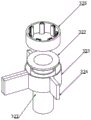
FIG. 10 is a schematic diagram of a bonding wire crystallization apparatus according to the present invention;
FIG. 11 is a schematic diagram showing an exploded structure of a bonding wire crystallization apparatus according to the present invention;
FIG. 12 is a schematic view of a sealing flange mounting structure of the present invention;
FIG. 13 is a schematic cross-sectional view of the outer cylinder of the present invention;
FIG. 14 is a schematic view of the electromagnetic coil mounting structure of the present invention;
FIG. 15 is a schematic diagram showing the exploded construction of a secondary crystallization assembly according to the present invention;
FIG. 16 is a schematic view of the mounting structure of the ring-mounted reflow copper tube of the present invention;
FIG. 17 is a schematic view of a cross-sectional structure of a discharge outer tube according to the present invention;
FIG. 18 is a schematic view of a shock mount mounting structure according to the present invention;
FIG. 19 is a schematic view of the mounting structure of the cleaning device of the present invention;
FIG. 20 is a schematic diagram of a front view of a hanger of the present invention;
FIG. 21 is a schematic view of a rear view of a hanger of the present invention;
FIG. 22 is an exploded view of the cleaning device of the present invention;
fig. 23 is a schematic view of the installation structure of the sponge cover of the present invention.
In the figure: support frame 100, water storage box 110, hanger 120, L-shaped plate 130, guide hole 140, hanging frame 150, moving block 160, guide wheel 170, cylinder 180, motor one 190, smelting device 200, traction rod 201, base 210, limit groove 211, liquid outlet 212, bottom lining ring 220, clamping groove 221, crescent plate 222, support tube 230, concave surface 231, intermediate frequency induction ring 232, top lining ring 240, crucible one 250, semi-convex ring 251, liquid outlet one 252, crucible two 260, liquid outlet two 261, sealing cylinder 270, sealing cover 271, vacuum valve 272, argon valve 273, discharge assembly 280, C-shaped plate 281, limit post 282, screw 283, support rod 284, plug 285, motor two 286, top cover 290, reaction chamber 291, bonding wire crystallization device 300, rodless cylinder 310, primary crystallization assembly 320, outer cylinder 321 graphite sleeve 322, sealing water collar 323, connecting rod 324, solenoid 325, pipe interface 326, sealing flange 327, half arc plate 328, secondary crystallization assembly 330, outer sleeve 331, support plate 332, ribs 333, inner sleeve 334, ring backflow copper tube 335, stainless steel tube 336, hanger 337, spring 338, stop lever 339, support base 340, chute 341, support arm 342, shock mount 350, slider 351, bump 352, crystallization hole 353, spring rod 354, discharge outer tube 360, discharge inner tube 370, spiral water channel 380, hose 390, cleaning device 400, housing 410, annular hole 420, annular gear 430, gear one 431, triangular plate 440, rotating shaft 441, hollow tube 450, sponge sleeve 460, gear one 470, gear two 471, through hole 472, gear three 473, motor three 480.
Detailed Description
The preferred embodiments of the present invention will be described below with reference to the accompanying drawings, it being understood that the preferred embodiments described herein are for illustration and explanation of the present invention only, and are not intended to limit the present invention.
Referring to fig. 1-23, the preparation method of the gold alloy bonding wire provided by the invention comprises the following steps of material preparation, alloy smelting, drawing casting, wire drawing, annealing and wire winding:
step one: preparing materials, namely weighing raw materials of the gold alloy bonding wire according to the required weight, wherein the gold alloy bonding wire is composed of metal materials with the following weight ratio of 10-30% of silver, 20-30% of nickel, 0.5-2% of palladium, 5-50ppm of trace additive elements of calcium and 10-200ppm of cerium, and the balance of gold;
step two: alloy smelting and drawing casting, namely smelting raw materials of the gold alloy bonding wire into alloy solution, stirring and vibrating the alloy solution through electromagnetic force, cooling the alloy solution for crystallization by matching with repeated cooling, so that the convection, heat transfer and mass transfer processes of the melt are enhanced, the superheat degree of the alloy solution is improved and eliminated, the equiaxed crystal rate of a casting blank can be improved, the casting blank with good solidification structure is obtained, the solidification of the casting blank is controlled, an alloy rod with the diameter of 5-10mm is formed, and meanwhile, the surface of the alloy rod is erased and polished;
Step three: drawing, namely drawing the drawn and cast alloy rod to obtain a bonding wire semi-finished product with the diameter of 0.08-0.5mm through a drawing process, drawing the bonding wire semi-finished product into an alloy wire with the diameter of 0.26mm through a middle drawing device, wherein the elongation of the middle drawing die is 9-18%, the drawing speed is 60-180m/min, and drawing the bonding wire into an alloy bonding wire with the diameter of 25 mu m through a fine drawing and superfine drawing device;
step four: annealing, namely carrying out intermediate annealing on the bonding wire semi-finished product for a plurality of times in the wire drawing process, wherein N2 is adopted as annealing atmosphere in the annealing process, the effective length of the annealing furnace is 600-1000mm, the annealing temperature is 600-800 ℃, and the annealing speed is 40-80m/min;
step five: winding, namely placing the qualified gold alloy bonding wire on a rewinder for winding, wherein the winding tension is 6-35g, and the winding speed is 400-650rpm;
the second step is that the equipment comprises a supporting frame 100, a smelting device 200, a bonding wire crystallization device 300 and a cleaning device 400, wherein the smelting device 200 is arranged at the top of the supporting frame 100, the smelting device 200 has the effect of smelting and mixing gold, silver, palladium, nickel and trace calcium and cerium, a hanging bracket 120 is fixedly arranged at the bottom of the supporting frame 100, the bonding wire crystallization device 300 is arranged at the top of the hanging bracket 120, the top of the bonding wire crystallization device 300 is connected with the bottom of the smelting device 200, the bonding wire crystallization device 300 has the effect of crystallizing and casting alloy after smelting and mixing into alloy bars, the cleaning device 400 is arranged at the bottom of the bonding wire crystallization device 300, the cleaning device 400 has the effect of erasing and polishing cooling liquid on the surface of the alloy bars, the cleaning device 400 comprises a shell 410, a ring hole 420 is formed at the top and the bottom of the shell 410, and the central axes of the smelting device 200, the bonding wire crystallization device 300 and the cleaning device 400 are mutually perpendicular;
Further, the smelting device 200 includes a base 210, specifically, the base 210 is fixedly installed on the inner wall of the top of the support frame 100, the support frame 100 has supporting and installing functions on the base 210, a limit groove 211 is formed in the inner wall of the base 210, a liquid outlet nozzle 212 is formed in the bottom of the inner wall of the limit groove 211, a bottom lining ring 220 is arranged at the top of the base 210, a support pipe 230 is arranged at the top of the bottom lining ring 220, a top lining ring 240 is arranged at the top of the support pipe 230, crescent plates 222 are fixedly installed on two sides of the bottom lining ring 220 and the top lining ring 240, concave surfaces 231 are formed on the outer walls of the support pipe 230 and the base 210, the bottom lining ring 220 is connected with the support pipe 230 and the base 210 respectively through the concave surfaces 231 of the crescent plates 222, the crescent plates 222 and the concave surfaces 231 are in a seamless inserting structure, and the bottom lining ring 220, the support pipe 230 and the top lining ring 240 are convenient to detach and install;
further, clamping grooves 221 are formed on two sides of the tops of the top lining ring 240 and the bottom lining ring 220, specifically, a first crucible 250 is arranged on the inner wall of the bottom lining ring 220, a second crucible 260 is arranged on the inner wall of the top lining ring 240, a first liquid outlet 252 and a second liquid outlet 261 are formed at the bottoms of the first crucible 250 and the second crucible 260 respectively, semi-convex rings 251 are fixedly arranged on two sides of the tops of the first crucible 250 and the second crucible 260, the first crucible 250 and the second crucible 260 are respectively arranged on the inner walls of the bottom lining ring 220 and the top lining ring 240 through the clamping grooves 221 of the semi-convex rings 251, the clamping grooves 221 and the semi-convex rings 251 are in seamless splicing structures, the top lining ring 240, the bottom lining ring 220, the first crucible 250 and the second crucible 260 are convenient to detach and install, the bottom of the second crucible 260 is arranged on the inner wall of the supporting tube 230, an intermediate frequency induction ring 232 is fixedly arranged on the inner wall of the supporting tube 230, the intermediate frequency induction ring 232 is not contacted with the second crucible 260, the intermediate frequency induction ring 232 is made of spiral copper tubes, when the magnetic flux enclosed by the conductor loop changes, induced potential is generated in the loop, and similarly, the conductor in the alternating magnetic field generates induced potential under the action of electromagnetic induction, induced current is formed in the conductor, the induced current overcomes the resistance of the conductor to generate joule heat, the conductor is heated by the heat to heat and melt, the intermediate frequency induction coil 232 has the heating function on the crucible two 260 and the raw material of the alloy bonding wire in the crucible two 260, the bottom of the crucible one 250 is inserted into the inner wall of the limiting groove 211 and is in sealing connection with the inner wall of the base 210, the limiting groove 211 is in sealing connection with the liquid outlet 212, the bottom of the liquid outlet one 252 is connected with the liquid outlet 212, the smelting device 200 comprises a sealing cylinder 270, the sealing cylinder 270 is sleeved on the outer walls of the bottom lining ring 220, the supporting tube 230, the top lining ring 240 and the base 210, the bottom of the sealing cylinder 270 is welded with the top of the base 210, the sealing cylinder 270 is fixedly connected with the base 210, and then the bottom lining ring 220, the first crucible 250, the supporting tube 230, the top lining ring 240 and the second crucible 260 are detachably arranged in the sealing cylinder 270 in sequence, wherein the bottom lining ring 220, the supporting tube 230 and the top lining ring 240 are made of high-temperature ceramics;
Further, the bonding wire crystallization device 300 comprises a primary crystallization component 320 and a secondary crystallization component 330, in particular, the primary crystallization component 320 has stirring and cooling functions on alloy melt, the secondary crystallization component 330 has crystallization and cooling functions on alloy melt, the primary crystallization component 320 and the secondary crystallization component 330 are mutually perpendicular, the primary crystallization component 320 comprises an outer cylinder 321, a graphite sleeve 322 is fixedly arranged on the inner wall and the bottom of the outer cylinder 321, the top of the graphite sleeve 322 is mutually parallel to the top of the inner wall of the outer cylinder 321, the graphite sleeve 322 is fixedly arranged on the inner wall of the outer cylinder 321, the bottom extends to the lower part of the outer cylinder 321, the graphite sleeve 322 adopts a cylindrical hollow sleeve made of graphite, the graphite is a transitional crystal among atomic crystals, metal crystals and molecular crystals, the melting point of the transitional crystal is 3652-3697 ℃, the high temperature resistant effect is achieved, a sealing water collar 323 is arranged on the outer wall of the graphite sleeve 322, the sealing water lantern ring 323 is arranged on the inner wall of the outer cylinder 321, connecting rods 324 are fixedly arranged on two sides of the sealing water lantern ring 323, one side of each connecting rod 324 is fixedly connected with the inner wall of the outer cylinder 321, the connecting rods 324 have the function of fixedly mounting the sealing water lantern ring 323 on the inner wall of the outer cylinder 321, the graphite sleeve 322 is not connected with the sealing water lantern ring 323, a gap is arranged between the graphite sleeve 322 and the sealing water lantern ring 323, the sealing water lantern ring 323 has the function of facilitating cooling water circulation, an electromagnetic coil 325 is fixedly arranged on the inner wall of the sealing water lantern ring 323, the sealing water lantern ring 323 adopts sealing cylindrical stainless steel as a material, a cavity is arranged inside the sealing water lantern ring 323, the electromagnetic coil 325 has the waterproof function, the electromagnetic coil 325 is arranged as a stator and a stator winding of a stepping motor, a sealing wire guide plate (not labeled in the figure) on one side of the sealing water lantern ring 323 is fixedly connected with the outer cylinder 321, the electromagnetic coil 325 has the function of sealing mounting the conductive wire, the two sides of the outer cylinder 321 are provided with the pipeline interfaces 326, the pipeline interfaces 326 are provided with two groups, when the stator winding of the electromagnetic coil 325 is electrified, the stator winding generates a vector magnetic field, and as the alloy melt contains nickel element which has magnetism, the nickel element in the alloy melt is driven to rotate by the magnetic field, the nickel element drives the alloy melt to rotate, so that the magnetic field direction of the alloy melt is consistent with the magnetic field direction of the stator, when the vector magnetic field of the stator rotates by an angle, the alloy melt also rotates by an angle along with the magnetic field, and each electric pulse is input, and the motor further rotates by an angle. The output angular displacement is in direct proportion to the input pulse number, the rotating speed is in direct proportion to the pulse frequency, the principle that like poles repel and opposite poles attract of a magnetic field is utilized, the magnetic field is utilized to push magnetic alloy melt to rotate, the top of an outer cylinder 321 is fixedly provided with a sealing flange 327, the top of the sealing flange 327 is fixedly connected with the bottom of a base 210, the top of a graphite sleeve 322 is in sealing connection with the bottom of a liquid outlet 212, the outer wall of the bottom of the graphite sleeve 322 is provided with a half arc plate 328, the half arc plate 328 is provided with two groups, and a pipeline interface 326 is arranged as a cooling liquid inlet and outlet;
Further, the secondary crystallization assembly 330 comprises an outer sleeve 331, an inner sleeve 334 is fixedly arranged on the inner wall of the outer sleeve 331, a ring-mounted backflow copper pipe 335 is fixedly arranged on the inner wall of the inner sleeve 334, two ends of the ring-mounted backflow copper pipe 335 are arranged at the bottom of the inner sleeve 334, two ends of the ring-mounted backflow copper pipe 335 are provided with cooling liquid inlets and outlets, a stainless steel pipe 336 is fixedly arranged on the inner wall of the inner sleeve 334, the stainless steel pipe 336 is provided with a high-temperature resistant stainless steel pipe, the high-temperature resistant stainless steel pipe is suitable for manufacturing various furnace components, the highest working temperature is 1300 ℃, the continuous use temperature is 1150 ℃, lugs 337 are fixedly arranged on two sides of the top of the stainless steel pipe 336, the lugs 337 are inserted between two groups of half arc plates 328, the lugs 337 are in sliding connection with the half arc plates 328, the lugs 337 are in sliding connection, the bottoms of the graphite sleeves 322 are inserted into the inner wall of the top of the stainless steel pipe 336, the graphite sleeve 322 is in non-contact with the stainless steel pipe 336, the top diameter of the stainless steel pipe 336 is larger than the middle, the tops of the two groups of lugs are fixedly arranged with springs 338, the tops of the springs 338, and the bottoms of the springs 337 are fixedly connected with the bottoms of the outer cylinder 321, and have the functions of connecting the lugs 337 with the bottoms of the lugs 338;
Further, the bonding wire crystallization device 300 comprises a supporting seat 340, specifically, a supporting arm 342 is fixedly installed at the center position of two sides of the supporting seat 340, a sliding groove 341 is formed in one side of the supporting seat 340, two groups of sliding grooves 341 are formed, a shock absorbing seat 350 is arranged on one side of the supporting seat 340, a crystallization hole 353 is fixedly installed on the inner wall of the shock absorbing seat 350, the top of the crystallization hole 353 is fixedly connected with the bottom of a stainless steel tube 336, a sliding block 351 is fixedly installed on one side of the shock absorbing seat 350, two groups of sliding blocks 351 are arranged, the shock absorbing seat 350 is installed on the outer wall of the supporting seat 340 through the sliding grooves 341 in a sliding manner, a bump 352 is fixedly installed on two sides of the shock absorbing seat 350, the bump 352 is mutually perpendicular to the supporting arm 342, a spring rod 354 is fixedly installed at the bottom of the bump 352, the spring rod 354 is composed of a hydraulic rod and a spring, the shock absorbing function is achieved on the shock absorbing seat 350, and the bottom of the spring rod 354 is fixedly connected with the top of the supporting arm 342;
further, a discharging outer tube 360 is fixedly installed at the bottom of one side of the supporting seat 340, specifically, a discharging inner tube 370 is fixedly installed on the inner wall of the discharging outer tube 360, the middle part of the discharging outer tube 360 is in sealing connection with the top outer wall of the discharging inner tube 370 and is not connected with the bottom, a cavity is formed between the bottom outer walls of the discharging outer tube 360 and the discharging inner tube 370, a spiral water channel 380 is installed, cooling water flows into the spiral water channel 380, the contact area between the cooling water and the discharging inner tube 370 is conveniently increased, the discharging inner tube 370 is mutually perpendicular to the crystallization hole 353, the spiral water channel 380 is fixedly installed at the joint of the discharging inner tube 370 and the discharging outer tube 360, a hose 390 is arranged on the outer wall of the discharging outer tube 360, the hose 390 has the function of guiding cooling water into the spiral water channel 380, the input end of the hose 390 is mutually connected with the output end of the circular backflow copper tube 335 and the output end of the circular backflow tube 326, the input end of the hose 390 is provided with a tee joint (not labeled in the drawing), and the output end of the circular backflow copper tube 335 and the output end of the pipeline interface 326 are connected;
Further, the top cover 290 is detachably mounted on the top of the seal cylinder 270, specifically, a seal cover 271 is fixedly mounted on one side of the outer wall of the seal cylinder 270, the inner wall of the seal cover 271 is connected with the inner wall of the seal cylinder 270, a discharging component 280 is arranged on the inner wall of the seal cover 271, the discharging component 280 comprises a C-shaped plate 281, the right side of the C-shaped plate 281 is fixedly connected with the inner wall of the seal cover 271, a screw 283 is arranged on one side of the C-shaped plate 281, two ends of the screw 283 are respectively movably connected with the top and the bottom of the C-shaped plate 281, a bearing is mounted at the joint of the screw 283 and the C-shaped plate 281, a limit post 282 is arranged on one side of the screw 283, two ends of the limit post 282 are respectively fixedly connected with the top and the bottom of the C-shaped plate 281, the discharging component 280 comprises a supporting rod 284, the screw rod 283 is inserted into the right end of the inner wall of the supporting rod 284 and is in threaded connection with the supporting rod 284, the bottom of the sealing cover 271 is fixedly provided with a second motor 286, the output end of the second motor 286 is inserted into the bottom of the C-shaped plate 281 and is connected with the screw rod 283, the limiting post 282 is inserted into the right end of the inner wall of the supporting rod 284 and is in sliding connection with the supporting rod 284, the second motor 286 is set as a servo motor, the left end of the supporting rod 284 is arranged on the inner wall of the sealing cylinder 270, the output shaft of the second motor 286 is set as a magnetic fluid sealing shaft, the bottom of the left end of the supporting rod 284 is fixedly provided with a plug 285, the plug 285 is arranged on the inner wall of the second crucible 260 and is mutually perpendicular to the second liquid outlet 261, and the plug 285 is formed by high alumina raw materials and high-grade graphite through impact high-pressure molding and high-temperature treatment at 1300 ℃, so that the sealing device is suitable for flow control of cast steel;
Further, a reaction chamber 291 is arranged between the top of the top lining ring 240 and the inner wall of the sealing cylinder 270, specifically, a vacuum valve 272 is fixedly installed on one side of the outer wall of the sealing cylinder 270, the vacuum valve 272 has the function of externally connecting a vacuum pump, an argon valve 273 is fixedly installed on one side of the outer wall of the sealing cylinder 270, the argon valve 273 has the function of externally connecting an argon input pipeline, and the output ends of the vacuum valve 272 and the argon valve 273 are mutually connected with the reaction chamber 291;
further, the right side of the outer sleeve 331 is fixedly provided with a raised line 333, specifically, the raised line 333 is provided with two groups, the inner walls of the two groups of raised lines 333 are inserted with a limiting rod 339, the limiting rod 339 is in sliding connection with the raised line 333, the limiting rod 339 has a limiting effect on the outer sleeve 331, the top of the limiting rod 339 is fixedly connected with the bottom of the base 210, the left side of the outer sleeve 331 is fixedly provided with a supporting plate 332, one side of the hanging bracket 120 is fixedly provided with an L-shaped plate 130, the right side of the L-shaped plate 130 is fixedly provided with a rodless cylinder 310, the rodless cylinder 310 is a cylinder which is directly or indirectly connected with an external actuating mechanism by a piston and is enabled to realize reciprocating motion along with the piston, the right side output shaft of the rodless cylinder 310 is fixedly connected with the supporting plate 332, the bottom of the limiting rod 339 is fixedly connected with the top of the hanging bracket 120, the rodless cylinder 310 has a transmission effect on the outer sleeve 331, one side of the supporting seat 340 is fixedly connected with the top of the hanging bracket 120, the center position of the hanging bracket 120 is provided with a guide hole 140, and the discharging outer tube 360 is inserted into the inner wall of the guide hole 140;
Further, a hanging frame 150 is fixedly installed at the bottom of the hanging frame 120, specifically, a moving block 160 is arranged on the inner wall of the hanging frame 150, two groups of moving blocks 160 are arranged, a guide wheel 170 is installed on one side of each group of moving blocks 160, the moving block 160 has a supporting function on the guide wheel 170, a water storage box 110 is arranged at the bottom of the hanging frame 120, the water storage box 110 has a function of collecting cooling liquid flowing out of a discharging outer pipe 360, the outer wall of the water storage box 110 is fixedly connected with the inner wall of the supporting frame 100, a cleaning device 400 is installed between the hanging frame 120 and the water storage box 110, the bottom of a shell 410 is fixedly installed at the top of the water storage box 110, an inner gear ring 430 is fixedly installed at the center position of the inner wall of the shell 410, a first gear 431 is arranged on the inner wall of the inner gear ring 430, three groups of gears 431 are in meshed connection with the inner gear ring 430, a gear 470 is arranged between the three groups of gears 431, the gear 470 has a transmission function on the first gear 431, a through hole 472 is formed on the inner wall of the gear 470, the bottom of the gear shaft 470 is fixedly provided with a gear II 471, the gear shaft 470 is in meshed connection with three groups of gears I431, the top of the gear I431 is provided with a triangle plate 440, the top of the triangle plate 440 is movably provided with a rotating shaft 441, the joint of the triangle plate 440 and the rotating shaft 441 is provided with a bearing, the rotating shaft 441 is provided with three groups, the bottoms of the three groups of rotating shafts 441 are respectively fixedly connected with the three groups of gears I431, the gear I431 has transmission and supporting functions on the rotating shaft 441, the top of the three groups of rotating shafts 441 is provided with a sponge sleeve 460, the sponge sleeve 460 is detachably arranged on the outer wall of the rotating shaft 441, the top of the triangle plate 440 is fixedly provided with a hollow tube 450, the diameters of the hollow tube 450 and a through hole 472 are larger than the diameter of the traction rod 201, the bottom of the water storage box 110 is fixedly provided with a motor III 480, the output shaft of the motor III 480 is arranged at the bottom of the inner wall of the casing 410, the top of the casing 410 is provided with a conical shape, the motor III 480 is provided with a servo motor, the output shaft of the motor III 473 is fixedly provided with a gear, the third gear 473 is in meshed connection with the second gear 471, the third motor 480 has a transmission function on the third gear 473, the third gear 473 has a transmission function on the second gear 471, the smelting device 200 comprises a traction rod 201, the traction rod 201 is arranged on the inner walls of the through hole 472, the hollow pipe 450 and the annular hole 420 and the tops of the traction rod 201 are sequentially inserted into the inner walls of the discharging inner pipe 370 and the crystallization hole 353, the traction rod 201 is provided with an alloy rod formed by fastening crystallized alloy melt on the top of the traction rod 201, and the alloy rod formed by crystallizing the alloy melt is pulled downwards to continuously pull out along with the traction rod 201;
Further, the two sets of moving blocks 160 are movably connected with the inner wall of the hanging frame 150 and symmetrically arranged, specifically, the two sides of the hanging frame 150 are fixedly provided with the air cylinders 180, the air cylinders 180 are cylindrical metal parts for guiding the pistons to reciprocate in the cylinders in a straight line, the output shafts of the two sets of air cylinders 180 are fixedly connected with one side of the two sets of moving blocks 160 respectively, the two sets of air cylinders 180 have the function of pushing the two sets of moving blocks 160 to move left and right on the inner wall of the hanging frame 150 respectively, the two sets of guide wheels 170 are adjusted, one side of the one set of moving blocks 160 is fixedly provided with the first motor 190, the first motor 190 is arranged as a servo motor, the output shaft of the first motor 190 is fixedly connected with the one set of guide wheels 170, and the first motor 190 has a transmission function on the guide wheels 170.
An alloy bonding wire is prepared by a preparation method of the alloy bonding wire.
The application process of the invention is as follows: when the invention is used, workers in the field need to connect the input end of the annular reflux copper pipe 335 with a cooling liquid pipeline, connect the output end of the annular reflux copper pipe 335 with the output end of a hose 390, connect one end of a pipeline interface 326 with the cooling liquid pipeline, connect the other end of the pipeline interface 326 with the output end of the hose 390, plug a traction rod 201 into the inner wall of a discharging inner pipe 370 and a crystallization hole 353, weigh raw materials of gold, silver, nickel, palladium, calcium and cerium according to the required weight, put into a crucible II 260, close a top cover 290, start a vacuum pump to vacuumize a reaction cavity 291 through a vacuum valve 272, start an intermediate frequency induction coil 232 to heat the crucible II 260 when the vacuum degree in the reaction cavity 291 reaches 0.1X10 < -3 > Pa, completely melt alloy, maintain the temperature, refine for 10-20 minutes, and stop heating, the melted alloy melt is cooled to room temperature along with the reaction chamber 291, the heating is repeated for 2 to 3 times, the vacuumizing is stopped, argon is input through an argon gas pipeline externally connected with an argon gas valve 273, when the pressure reaches 0.01 to 0.05Pa, a screw rod 283 drives a supporting rod 284 to move upwards through a motor two 286, a plug 285 is separated from a liquid outlet 252 of a crucible two 260, the alloy melt flows into the crucible one 250 through the liquid outlet 252 of the crucible two 260, flows into a liquid outlet 212 through the liquid outlet 252 of the crucible one 250, flows into a graphite sleeve 322 through the liquid outlet 212, a cooling liquid is input into an outer cylinder 321 through a pipeline interface 326, the graphite sleeve 322 is cooled, an electromagnetic coil 325 is started at the same time, the alloy melt in the graphite sleeve 322 is stirred, the alloy melt is subjected to first crystallization, the alloy melt after the first crystallization flows into a stainless steel pipe 336, the cooling liquid is conveyed into a circular backflow copper pipe 335, the stainless steel tube 336 is cooled down secondarily through the inner sleeve 334, the rodless cylinder 310 drives the outer sleeve 331 to move up and down, the stainless steel tube 336 vibrates while moving up and down, alloy melt is tightly deposited in the stainless steel tube 336 to perform secondary crystallization, alloy melt for secondary crystallization is deposited on the top of the traction rod 201, then the cylinder 180 pushes the moving block 160 to move, two groups of guide wheels 170 squeeze the traction rod 201 inwards, the motor I190 is started, the motor I190 drives the guide wheels 170 to rotate, the guide wheels 170 drive the traction rod 201 to move downwards, the traction rod 201 drives alloy melt continuously performing secondary crystallization to move downwards, the alloy melt is continuously pulled out through the discharging inner tube 370 to form an alloy rod, meanwhile, the cooling liquid conveyed by the output ends of the circulating reflux copper tube 335 and the pipeline interface 326 flows into the hose 390, the cooling liquid flows into the spiral water channel 380 of the discharging outer tube 360 through the hose 390 to cool the outer wall of the discharging inner tube 370, flows out of the bottom of the discharging outer tube 360 through the spiral water channel 380, is sprayed on the surface of the alloy rod, flows into the water storage box 110 through the shell 410, the rear traction rod 201 pulls the alloy rod into the shell 410, sequentially passes through the hollow tube 450 and the inside of the through hole 472, and is pulled out through the annular hole 420, the motor three 480 is started, the motor three 480 drives the gear three 473 to rotate, the gear three 473 drives the gear two 471 to rotate, the gear two 471 drives the gear shaft 470, the gear shaft 470 drives the three groups of gears one 431, the gear one 431 is meshed with the inner gear ring 430, and the three groups of gears one 431 revolve around the gear shaft 470 when rotating in the inner gear ring 430, so that the sponge sleeve 460 rotates and revolves, and the cooling liquid on the surface of the alloy rod is erased and polished.
While the invention has been described in detail in the foregoing general description and specific examples, it will be apparent to those skilled in the art that modifications and improvements can be made thereto. Accordingly, such modifications or improvements may be made without departing from the spirit of the invention and are intended to be within the scope of the invention as claimed.
Claims (7)
1. A preparation method of a gold alloy bonding wire is characterized by comprising the following steps: the method comprises the steps of material preparation, alloy smelting, casting, wire drawing, annealing and wire winding, and specifically comprises the following steps:
step one: preparing materials, namely weighing raw materials of the gold alloy bonding wire according to the required weight, wherein the gold alloy bonding wire is composed of metal materials with the following weight ratio of 10-30% of silver, 20-30% of nickel, 0.5-2% of palladium, 5-50ppm of trace additive elements of calcium and 10-200ppm of cerium, and the balance of gold;
step two: alloy smelting and drawing casting, namely smelting a gold alloy bonding wire raw material into alloy melt, stirring and vibrating the alloy melt through electromagnetic force, and crystallizing the alloy melt by matching with cooling for multiple times, so that the convection, heat transfer and mass transfer processes of the melt are enhanced, the superheat degree of the alloy melt is improved, the equiaxed crystal rate of a casting blank can be improved, the casting blank with good solidification structure is obtained, the solidification of the casting blank is controlled, an alloy rod with the diameter of 5-10mm is formed, and meanwhile, the surface of the alloy rod is erased and polished;
Step three: drawing, namely drawing the drawn and cast alloy rod to obtain a bonding wire semi-finished product with the diameter of 0.08-0.5mm through a drawing process, drawing the bonding wire semi-finished product into an alloy wire with the diameter of 0.26mm through a middle drawing device, wherein the elongation of the middle drawing die is 9-18%, the drawing speed is 60-180m/min, and drawing the bonding wire into an alloy bonding wire with the diameter of 25 mu m through a fine drawing and superfine drawing device;
step four: annealing, in which the semi-finished product of the bonding wire is subjected to a plurality of intermediate anneals in the wire drawing process, and N is adopted in the annealing process 2 As annealing atmosphere, the effective length of the annealing furnace is 600-1000mm, the annealing temperature is 600-800 ℃, and the annealing speed is 40-80m/min;
step five: winding, namely placing the qualified gold alloy bonding wire on a rewinder for winding, wherein the winding tension is 6-35g, and the winding speed is 400-650rpm;
the operation steps of smelting and casting the gold alloy bonding wire by the equipment in the second step are as follows:
s1: weighing raw materials of gold, silver, nickel, palladium, calcium and cerium, putting into a crucible II (260), closing a top cover (290), vacuumizing a reaction cavity (291) through a vacuum valve (272), and when the vacuum degree in the reaction cavity (291) reaches 0.1X10 -3 When Pa, starting an intermediate frequency induction coil (232) to heat the crucible II (260), when the temperature in the crucible II (260) reaches 1050-1250 ℃, completely melting the alloy, maintaining the temperature, refining for 10-20 minutes, stopping heating, cooling the melted alloy melt to room temperature along with a reaction cavity (291), repeatedly heating for 2-3 times, stopping vacuumizing, and inputting argon through an argon gas valve (273) externally connected with an argon gas pipeline to enable the pressure to reach 0.01-0.05Pa;
S2: the screw rod (283) drives the supporting rod (284) to move upwards through the motor II (286), so that the plug (285) is separated from the liquid outlet I (252) of the crucible II (260), alloy melt flows into the crucible I (250) through the liquid outlet II (261) of the crucible II (260), and flows into the liquid outlet (212) through the liquid outlet I (252) of the crucible I (250);
s3: alloy melt flows into the graphite sleeve (322) through the liquid outlet nozzle (212), cooling liquid is input into the outer cylinder (321) through the pipeline interface (326), so that the graphite sleeve (322) is cooled, meanwhile, the electromagnetic coil (325) is started, the alloy melt in the graphite sleeve (322) is stirred, the alloy melt is subjected to primary crystallization, the alloy melt after the primary crystallization flows into the stainless steel pipe (336), the cooling liquid is conveyed into the annular backflow copper pipe (335), the stainless steel pipe (336) is subjected to secondary cooling through the inner sleeve (334), and meanwhile, the rodless cylinder (310) drives the outer sleeve (331) to move up and down, and vibration is generated while the stainless steel pipe (336) moves up and down, so that the alloy melt is tightly deposited in the stainless steel pipe (336) to perform secondary crystallization;
S4: the alloy melt for secondary crystallization is deposited on the top of a traction rod (201), a moving block (160) is pushed to move through an air cylinder (180), so that two groups of guide wheels (170) are inwards extruded to the traction rod (201), a motor I (190) drives the guide wheels (170) to rotate, the guide wheels (170) drive the traction rod (201) to move downwards, the traction rod (201) drives the alloy melt for continuous secondary crystallization to move downwards, and the alloy melt is continuously pulled out through a discharging inner pipe (370) to form an alloy rod with the diameter of 5-10mm, and the pulling speed is 20-60mm/min;
s5: meanwhile, cooling liquid conveyed by the output ends of the annular reflux copper pipe (335) and the pipeline connector (326) flows into a hose (390), flows into a spiral water channel (380) of the discharging outer pipe (360) through the hose (390), cools the outer wall of the discharging inner pipe (370), flows out of the bottom of the discharging outer pipe (360) through the spiral water channel (380), and flows into the water storage box (110) through the shell (410) after being sprayed on the surface of the alloy rod;
s6: the traction rod (201) pulls the alloy rod into the shell (410), sequentially passes through the hollow tube (450) and the inside of the through hole (472) and is pulled out through the annular hole (420), the motor III (480) drives the gear III (473) to rotate, the gear III (473) drives the gear II (471) to rotate, the gear II (471) drives the gear shaft (470), the gear shaft (470) drives the three groups of gears I (431), the gears I (431) are meshed with the inner gear ring (430), the three groups of gears I (431) revolve around the gear shaft (470) while rotating in the inner gear ring (430), so that the sponge sleeve (460) carries out self-transmission and revolution, and the cooling liquid on the surface of the alloy rod is erased and polished;
In the second step, the equipment comprises a supporting frame (100), a smelting device (200), a bonding wire crystallization device (300) and a cleaning device (400), wherein the smelting device (200) is arranged at the top of the supporting frame (100), a hanging bracket (120) is fixedly arranged at the bottom of the supporting frame (100), the bonding wire crystallization device (300) is arranged at the top of the hanging bracket (120), the top of the bonding wire crystallization device (300) is connected with the bottom of the smelting device (200), the cleaning device (400) is arranged at the bottom of the bonding wire crystallization device (300), the cleaning device (400) comprises a shell (410), an annular hole (420) is formed in the top and the bottom of the shell (410), and the smelting device (200), the bonding wire crystallization device (300) and the central shaft of the cleaning device (400) are mutually perpendicular;
smelting device (200) including base (210), base (210) fixed mounting is at support frame (100) top inner wall, spacing groove (211) have been seted up to base (210) inner wall, play liquid mouth (212) have been seted up to spacing groove (211) inner wall bottom, base (210) top is equipped with bottom backing ring (220), bottom backing ring (220) top is equipped with stay tube (230), stay tube (230) top is equipped with top backing ring (240), bottom backing ring (220) and top backing ring (240) both sides fixed mounting have crescent moon plate (222), concave surface (231) have been seted up to stay tube (230) and base (210) outer wall, bottom backing ring (220) are connected with stay tube (230) and base (210) respectively through crescent moon plate (222) grafting concave surface (231) messenger's top and bottom, top backing ring (240) are installed at stay tube (230) top through crescent moon plate (222) grafting concave surface (231);
Clamping grooves (221) are formed in two sides of the tops of the top lining ring (240) and the bottom lining ring (220), a first crucible (250) is arranged on the inner wall of the bottom lining ring (220), a second crucible (260) is arranged on the inner wall of the top lining ring (240), a first liquid outlet (252) and a second liquid outlet (261) are formed in the bottoms of the first crucible (250) and the second crucible (260) respectively, semi-convex rings (251) are fixedly arranged on two sides of the tops of the first crucible (250) and the second crucible (260), the first crucible (250) and the second crucible (260) are respectively arranged on the inner wall of the bottom lining ring (220) and the inner wall of the top lining ring (240) through the semi-convex rings (251) in a plugging mode, the bottoms of the second crucible (260) are arranged on the inner wall of the supporting tube (230), an intermediate frequency induction ring (232) is fixedly arranged on the inner wall of the supporting tube (230), the bottoms of the intermediate frequency induction ring (232) are not contacted with the second crucible (260), the bottoms of the first crucible (250) are plugged into the inner wall of the limiting grooves (211) to be connected with the inner wall of the base (210) in a sealing mode, the bottoms of the first liquid outlet (252) and the inner wall of the base (210) are connected with the outer wall of the supporting tube (200) in a sealing mode, the sealing device (200) is sleeved on the outer wall of the top lining ring (230) and the sealing device (200), the bottom of the sealing cylinder (270) is welded with the top of the base (210);
The bonding silk crystallization device (300) comprises a primary crystallization component (320) and a secondary crystallization component (330), the primary crystallization component (320) is mutually perpendicular to the secondary crystallization component (330), the primary crystallization component (320) comprises an outer cylinder (321), a graphite sleeve (322) is fixedly arranged on the inner wall and the bottom of the outer cylinder (321), the top of the graphite sleeve (322) is mutually parallel to the top of the inner wall of the outer cylinder (321), a sealing water collar (323) is arranged on the outer wall of the graphite sleeve (322), the sealing water collar (323) is arranged on the inner wall of the outer cylinder (321), connecting rods (324) are fixedly arranged on two sides of the sealing water collar (323), one side of each connecting rod (324) is fixedly connected with the inner wall of the outer cylinder (321), the graphite sleeve (322) is not connected with the sealing water collar (323), an electromagnetic coil (325) is fixedly arranged on the inner wall of the sealing water collar (323), a pipeline interface (326) is arranged on two groups, a sealing flange (327) is fixedly arranged on the top of the outer cylinder (321), a sealing flange (327) is fixedly arranged on the two sides of the outer cylinder (321), a sealing flange (322) and the bottom of the outer cylinder (321) is fixedly connected with a sealing flange (322) and the sealing water collar (322), the half arc plate (328) is provided with two groups;
The secondary crystallization assembly (330) comprises an outer sleeve (331), an inner sleeve (334) is fixedly arranged on the inner wall of the outer sleeve (331), a ring-mounted reflux copper pipe (335) is fixedly arranged on the inner wall of the inner sleeve (334), two ends of the ring-mounted reflux copper pipe (335) are arranged at the bottom of the inner sleeve (334), stainless steel pipes (336) are fixedly arranged on the inner wall of the inner sleeve (334), lugs (337) are fixedly arranged on two sides of the top of the stainless steel pipes (336), the lugs (337) are inserted between two groups of half arc plates (328), the lugs (337) are in sliding connection with the half arc plates (328), the bottom of the graphite sleeve (322) is inserted on the inner wall of the top of the stainless steel pipes (336), the graphite sleeve (322) is not contacted with the stainless steel pipes (336), springs (338) are fixedly arranged on the tops of the two groups of the lugs (337), and the tops of the springs (338) are fixedly connected with the bottom of the outer cylinder (321).
The bonding wire crystallization device (300) comprises a supporting seat (340), a supporting arm (342) is fixedly arranged at the center of two sides of the supporting seat (340), a sliding groove (341) is formed in one side of the supporting seat (340), two groups of sliding grooves (341) are formed in the supporting seat (340), a shock absorption seat (350) is arranged on one side of the supporting seat, a crystallization hole (353) is fixedly arranged on the inner wall of the shock absorption seat (350), the top of the crystallization hole (353) is fixedly connected with the bottom of a stainless steel tube (336), a sliding block (351) is fixedly arranged on one side of the shock absorption seat (350), two groups of sliding blocks (351) are arranged, the shock absorption seat (350) is connected with the outer wall of the supporting seat (340) in a sliding mode through the sliding block (351) in a plugging mode, a bump (352) is fixedly arranged on two sides of the shock absorption seat (350), the bump (352) is perpendicular to the supporting arm (342), a spring rod (354) is fixedly arranged at the bottom of the bump (352), and the bottom of the spring rod (354) is fixedly connected with the top of the supporting arm (342).
The utility model discloses a quick-change type water heater, including supporting seat (340), discharge outer tube (360) are installed to supporting seat (340) one side bottom fixed mounting, discharge outer tube (360) inner wall fixed mounting has ejection of compact inner tube (370), ejection of compact inner tube (370) and crystallization hole (353) mutually perpendicular, ejection of compact inner tube (370) and ejection of compact outer tube (360) junction fixed mounting have spiral water course (380), hose (390) have been seted up to ejection of compact outer tube (360) outer wall, hose (390) input and ejection of compact inner tube (370) and spiral water course (380) outer wall interconnect, hose (390) input and ring dress backward flow copper pipe (335) output and a set of pipeline interface (326) interconnect.
2. The method for preparing the gold alloy bonding wire according to claim 1, wherein the method comprises the following steps: the utility model discloses a sealing device, including sealed tube (270), sealing tube (270), top cover (290) is detachably installed at top, sealing tube (270) outer wall one side fixed mounting has sealed cowling (271), sealed cowling (271) inner wall and sealed tube (270) inner wall interconnect, sealed cowling (271) inner wall is equipped with blowing subassembly (280), blowing subassembly (280) are including C template (281), C template (281) right side and sealed cowling (271) inner wall fixed connection, C template (281) one side is equipped with screw rod (283), screw rod (283) both ends respectively with C template (281) top and bottom swing joint, screw rod (283) one side is equipped with spacing post (282), spacing post (282) both ends respectively with C template (281) top and bottom fixed connection, blowing subassembly (280) are including bracing piece (284), screw rod (283) are pegged graft in bracing piece (284) inner wall right-hand member and are connected with bracing piece (284) screw thread, sealed cowling (271) bottom fixed mounting has motor two (286), motor two (286) output is in C template bottom (281) and bracing piece (284) are at C template bottom and bracing piece (284) sliding connection (284) right side and bracing piece (284) are in bracing piece (284), the plug (285) is fixedly arranged at the bottom of the left end of the supporting rod (284), and the plug (285) is arranged on the inner wall of the second crucible (260) and is perpendicular to the second liquid outlet (261).
3. The method for preparing the gold alloy bonding wire according to claim 1, wherein the method comprises the following steps: a reaction cavity (291) is arranged between the top of the top lining ring (240) and the inner wall of the sealing cylinder (270), a vacuum valve (272) is fixedly arranged on one side of the outer wall of the sealing cylinder (270), an argon valve (273) is fixedly arranged on one side of the outer wall of the sealing cylinder (270), and the output ends of the vacuum valve (272) and the argon valve (273) are connected with the reaction cavity (291).
4. The method for preparing the gold alloy bonding wire according to claim 1, wherein the method comprises the following steps: the utility model discloses a lifting device for a lifting device, including outer tube (331) right side fixed mounting has sand grip (333), sand grip (333) are equipped with two sets of, two sets of sand grip (333) inner wall grafting has gag lever post (339), gag lever post (339) and sand grip (333) sliding connection, gag lever post (339) top and base (210) bottom fixed connection, outer tube (331) left side fixed mounting has backup pad (332), gallows (120) one side fixed mounting has L template (130), L template (130) right side fixed mounting has rodless cylinder (310), rodless cylinder (310) right side output shaft and backup pad (332) fixed connection, gag lever post (339) bottom and gallows (120) top fixed connection, guide hole (140) have been seted up in gallows (120) central point put, ejection of compact outer tube (360) are pegged graft at guide hole (140) inner wall.
5. The method for preparing the gold alloy bonding wire according to claim 1, wherein the method comprises the following steps: the utility model discloses a water storage device, including hanging bracket (120), hanging bracket (150) bottom fixed mounting has hanging bracket (150), hanging bracket (150) inner wall is equipped with movable block (160), movable block (160) are equipped with two sets of, two sets of movable block (160) one side is installed and is guided wheel (170), hanging bracket (120) bottom is equipped with water storage box (110), water storage box (110) outer wall and support frame (100) inner wall fixed connection, cleaning device (400) are installed between hanging bracket (120) and water storage box (110), shell (410) bottom fixed mounting is in water storage box (110) top, shell (410) inner wall central point puts fixed mounting has ring gear (430), ring gear (430) inner wall is equipped with gear one (431), gear one (431) is equipped with three sets, three sets of gear one (431) are connected with ring gear (430) meshing, are equipped with tooth axle (470) between three sets of gear one (431), through-hole (470) are seted up on tooth axle (470) inner wall, tooth axle (470) bottom fixed mounting has gear two (470), tooth axle (441) 470) is equipped with three sets of gear (441) top (440) meshing with triangle (440), three groups pivot (441) bottom respectively with three groups gear one (431) fixed connection, three groups sponge cover (460) are installed at pivot (441) top, triangle-shaped (440) top fixed mounting has hollow tube (450), water storage box (110) bottom fixed mounting has motor three (480), motor three (480) output shaft installs in shell (410) inner wall bottom, motor three (480) output shaft fixed mounting has gear three (473), gear three (473) and gear two (471) meshing are connected, smelting device (200) include traction lever (201), traction lever (201) are installed at through-hole (472), hollow tube (450) and ring hole (420) inner wall and top are pegged graft in proper order in ejection of compact inner tube (370) and crystallization hole (353) inner wall.
6. The method for preparing the gold alloy bonding wire according to claim 5, wherein the method comprises the following steps: two groups of movable blocks (160) are movably connected with the inner wall of a hanging frame (150) and are symmetrically arranged, air cylinders (180) are fixedly arranged on two sides of the hanging frame (150), output shafts of the two groups of air cylinders (180) are fixedly connected with one side of each movable block (160), one group of movable blocks (160) is fixedly provided with a motor I (190), and output shafts of the motor I (190) are fixedly connected with one group of guide wheels (170).
7. A gold alloy bonding wire, characterized in that: a method of producing a gold alloy wire as claimed in any one of claims 1 to 6.
Priority Applications (1)
| Application Number | Priority Date | Filing Date | Title |
|---|---|---|---|
| CN202210914551.3A CN115261663B (en) | 2022-08-01 | 2022-08-01 | Gold alloy bonding wire and preparation method thereof |
Applications Claiming Priority (1)
| Application Number | Priority Date | Filing Date | Title |
|---|---|---|---|
| CN202210914551.3A CN115261663B (en) | 2022-08-01 | 2022-08-01 | Gold alloy bonding wire and preparation method thereof |
Publications (2)
| Publication Number | Publication Date |
|---|---|
| CN115261663A CN115261663A (en) | 2022-11-01 |
| CN115261663B true CN115261663B (en) | 2023-05-02 |
Family
ID=83747228
Family Applications (1)
| Application Number | Title | Priority Date | Filing Date |
|---|---|---|---|
| CN202210914551.3A Active CN115261663B (en) | 2022-08-01 | 2022-08-01 | Gold alloy bonding wire and preparation method thereof |
Country Status (1)
| Country | Link |
|---|---|
| CN (1) | CN115261663B (en) |
Families Citing this family (5)
| Publication number | Priority date | Publication date | Assignee | Title |
|---|---|---|---|---|
| CN117259713B (en) * | 2023-11-23 | 2024-02-09 | 龙口市龙蓬精密铜管有限公司 | Semi-solid forming device for copper alloy pipe fitting |
| CN117287966B (en) * | 2023-11-27 | 2024-01-23 | 四川威纳尔特种电子材料有限公司 | Smelting device and method for efficiently forming and producing blank pup joint for bonding wire |
| CN118081310B (en) * | 2024-04-26 | 2024-06-21 | 合肥工业大学 | Titanium-aluminum composite ring piece forming device and method |
| CN118223114B (en) * | 2024-05-22 | 2024-08-16 | 湖南省金特克科技有限公司 | Crystal growth furnace for silicon carbide |
| CN120885651B (en) * | 2025-07-31 | 2026-03-31 | 江苏金蚕电子科技有限公司 | A bonding alloy wire continuous casting furnace |
Citations (9)
| Publication number | Priority date | Publication date | Assignee | Title |
|---|---|---|---|---|
| US4838933A (en) * | 1987-01-15 | 1989-06-13 | Compagnie Europeenne Du Zirconium Cezus | Apparatus for melting and continuous casting of metals, the process involved and use of the apparatus |
| JPH1145902A (en) * | 1997-07-25 | 1999-02-16 | Sumitomo Metal Mining Co Ltd | Bonding wire |
| CN101040372A (en) * | 2004-09-30 | 2007-09-19 | 田中电子工业株式会社 | Gold Alloy Bonding Wire |
| CN102418001A (en) * | 2011-11-16 | 2012-04-18 | 浙江佳博科技股份有限公司 | A kind of bonding gold wire and its preparation method |
| CN103658572A (en) * | 2013-12-29 | 2014-03-26 | 山东亨圆铜业有限公司 | Copper pipe horizontal continuous casting gas shield crystallizer and method for preparing copper alloy pipe through copper pipe horizontal continuous casting gas shield crystallizer |
| CN107008873A (en) * | 2017-04-11 | 2017-08-04 | 上海大学 | Multi-mode electrically magnetic field homogenizes the preparation method and its device of metal strand |
| CN109767991A (en) * | 2019-01-15 | 2019-05-17 | 江西蓝微电子科技有限公司 | A kind of preparation method of high gold-content alloy bonding wire |
| CN110303125A (en) * | 2019-07-22 | 2019-10-08 | 攀钢集团攀枝花钢铁研究院有限公司 | Synergistic improvement control method for homogeneity and compactness of heavy rail steel in bloom |
| CN115533056A (en) * | 2022-09-23 | 2022-12-30 | 松山湖材料实验室 | A vacuum electromagnetic stirring vertical continuous casting method and equipment |
Family Cites Families (1)
| Publication number | Priority date | Publication date | Assignee | Title |
|---|---|---|---|---|
| TWI237334B (en) * | 2002-04-05 | 2005-08-01 | Nippon Steel Corp | A gold bonding wire for a semiconductor device and a method for producing the same |
-
2022
- 2022-08-01 CN CN202210914551.3A patent/CN115261663B/en active Active
Patent Citations (9)
| Publication number | Priority date | Publication date | Assignee | Title |
|---|---|---|---|---|
| US4838933A (en) * | 1987-01-15 | 1989-06-13 | Compagnie Europeenne Du Zirconium Cezus | Apparatus for melting and continuous casting of metals, the process involved and use of the apparatus |
| JPH1145902A (en) * | 1997-07-25 | 1999-02-16 | Sumitomo Metal Mining Co Ltd | Bonding wire |
| CN101040372A (en) * | 2004-09-30 | 2007-09-19 | 田中电子工业株式会社 | Gold Alloy Bonding Wire |
| CN102418001A (en) * | 2011-11-16 | 2012-04-18 | 浙江佳博科技股份有限公司 | A kind of bonding gold wire and its preparation method |
| CN103658572A (en) * | 2013-12-29 | 2014-03-26 | 山东亨圆铜业有限公司 | Copper pipe horizontal continuous casting gas shield crystallizer and method for preparing copper alloy pipe through copper pipe horizontal continuous casting gas shield crystallizer |
| CN107008873A (en) * | 2017-04-11 | 2017-08-04 | 上海大学 | Multi-mode electrically magnetic field homogenizes the preparation method and its device of metal strand |
| CN109767991A (en) * | 2019-01-15 | 2019-05-17 | 江西蓝微电子科技有限公司 | A kind of preparation method of high gold-content alloy bonding wire |
| CN110303125A (en) * | 2019-07-22 | 2019-10-08 | 攀钢集团攀枝花钢铁研究院有限公司 | Synergistic improvement control method for homogeneity and compactness of heavy rail steel in bloom |
| CN115533056A (en) * | 2022-09-23 | 2022-12-30 | 松山湖材料实验室 | A vacuum electromagnetic stirring vertical continuous casting method and equipment |
Also Published As
| Publication number | Publication date |
|---|---|
| CN115261663A (en) | 2022-11-01 |
Similar Documents
| Publication | Publication Date | Title |
|---|---|---|
| CN115261663B (en) | Gold alloy bonding wire and preparation method thereof | |
| CN104308107A (en) | Vertical guide type vacuum melting inert gas shielding continuous feeding continuous casting machine | |
| CN115464108B (en) | Continuous casting machine | |
| CN104174823A (en) | Clad material solid/liquid composite continuous-casting forming device and method | |
| CN107138699A (en) | Bonding wire continuous casting furnace | |
| CN206936315U (en) | Bonding wire continuous casting furnace | |
| CN212741131U (en) | Device for producing large-size quartz cylinder by continuous melting method | |
| CN210450879U (en) | A rotary vibration coupling stirring device | |
| CN106735006A (en) | A kind of solid rolling flexibility preparation method of single crystallization metal wire liquid and device | |
| CN114963757A (en) | Metal part processing production smelting equipment | |
| CN114875257A (en) | High-frequency induction heating solidification device and method for preparing high-temperature alloy | |
| CN2438526Y (en) | Continuous casting apparatus of alloy round blank for semi-solid processing | |
| CN104357673B (en) | Metal electric slag refusion and smelting method | |
| CN203245344U (en) | Continuously-connecting device of single crystal thin wire rod | |
| CN215824273U (en) | Granulation equipment for high-temperature atomization of metal alloy | |
| CN117047039B (en) | Casting method of high-strength shell of wind driven generator | |
| CN116352032A (en) | Multi-layer electromagnetic stirring pulping equipment and working method based on high and low temperature melt mixing | |
| CN208245768U (en) | Continuous water mold | |
| CN2859528Y (en) | Thermal melting loss and thermal fatigue test device of die-casting mold material in molten aluminum | |
| CN216540765U (en) | Intelligent continuous casting system | |
| CN118237701B (en) | A argon arc welding machine for the production of intelligent floor scrubbers | |
| CN206527342U (en) | Metallic particles production equipment and production system | |
| CN108788031A (en) | Continuous water mold and coagulation forming method | |
| CN114590783A (en) | A zone melting device and method for producing high-purity tellurium by targeted eddy current strengthening zone melting | |
| CN206905526U (en) | One kind rotation melt component and smelting apparatus |
Legal Events
| Date | Code | Title | Description |
|---|---|---|---|
| PB01 | Publication | ||
| PB01 | Publication | ||
| SE01 | Entry into force of request for substantive examination | ||
| SE01 | Entry into force of request for substantive examination | ||
| GR01 | Patent grant | ||
| GR01 | Patent grant |