Rail butt joint safety blocking device for I-steel translation trolley
Technical Field
The invention relates to conveying equipment, in particular to a rail butt joint safety blocking device of an I-steel translation trolley.
Background
In the i-steel rail conveying operation, some rail transfer operations are often required, such as: the workpiece is transferred from one conveying rail to the other conveying rail which is staggered with each other, the conventional method is to firstly translate the trolley to the movable rail and then butt the movable rail and the fixed rail through a travelling crane, but the problems are that: when the translation trolley is positioned on the movable track and is not butted with the fixed track, the translation trolley can slide out of the movable track to cause accidents.
Disclosure of Invention
The invention aims to provide a safe stopping device for rail butt joint of an I-steel translation trolley, which is novel in structure, safe, reliable and long in service life.
In order to achieve the purpose, the swing arm device comprises a fixed collision block assembly and a movable swing rod assembly, wherein the fixed collision block assembly comprises a bending support rod, a collision block, a first bottom plate and a first connecting plate, the collision block comprises a bending plate and a blocking plate, the bending plate comprises a horizontal plate and two inclined plates symmetrically arranged at the left end and the right end of the horizontal plate, the movable swing rod assembly comprises a roller, a first shaft, a first nut, a swing arm, a screw shaft, a second nut, a second bottom plate, a second connecting plate, a blocking block and two supports symmetrically arranged at the left side and the right side of the swing arm, the blocking plate is welded at the right side of the bending plate, the upper end of the bending support rod is connected with the blocking plate, the lower end of the bending support rod is connected with the first bottom plate, the first connecting plate is welded at the bottom of the first bottom plate, the screw shaft penetrates through the middle part of the swing arm, the two supports are arranged at the left end and the right end of the screw shaft, the two supports are arranged on the second bottom plate, the second connecting plate is welded at the bottom of the second bottom plate, the first shaft is connected with the blocking block through the nut, and the right end of the swing arm is arranged at the right end of the roller shaft.
The invention adopts the structure consisting of the fixed collision block component and the movable swing rod component, after the structure is adopted, when the translation trolley is positioned on the movable track, the swing arm in the movable swing rod component naturally droops under the action of the self gravity of the swing arm, so that the translation trolley can be effectively prevented from sliding out of the movable track, when the movable track is butted with the fixed track, the roller in the movable swing rod component rolls on the bending plate of the collision block in the fixed collision block component, the swing arm is driven to swing for an angle, and at the moment, the translation trolley can safely exit the movable track and carry out the fixed track. The invention has novel structure, safety, reliability and long service life.
Drawings
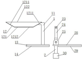
Fig. 1 is a front view of the present invention.
Fig. 2 is a left side view of the present invention.
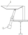
Fig. 3 is a schematic view of the application of the fixed i-rail and the movable i-rail when they are not butted.
Fig. 4 is a schematic view of the application of the fixed i-rail and the movable i-rail when they are butted.
Detailed Description
The embodiments of the invention are described in further detail below with reference to the accompanying drawings.
Referring to fig. 1 to 2, the present invention includes a fixed collision block assembly 1 and a movable swing link assembly 2, the fixed collision block assembly 1 includes a bending support rod 11, a collision block 12, a first base plate 13 and a first connecting plate 14, the collision block 12 includes a bending plate 121 with a straight upper opening and a large upper portion and a small lower portion and a blocking plate 122, the bending plate 121 includes a horizontal plate 1212 and two inclined plates 1211 symmetrically disposed at the left and right ends of the horizontal plate 1212, the movable swing link assembly 2 includes a roller 21, a first shaft 22, a first nut 23, a swing arm 24, a screw shaft 26, a second nut 27, a second base plate 28, a second connecting plate 29, a block 30 and two supports 25 symmetrically disposed at the left and right sides of the swing arm 24, the blocking plate 122 is welded to the right side of the bending plate 121, the upper end of the bending support rod 11 is connected with the blocking plate 122, the lower end of the bending support rod 11 is connected with the first base plate 13, the first connecting plate 14 is welded to the bottom of the first base plate 13, the screw shaft 26 is installed in the middle of the swing arm 24, the two supports 25 are installed to the left and right ends of the screw shaft 26, the swing arm 28 are installed to the upper end of the swing arm 24, the swing arm 28 is installed to the connecting plate 22, the left end of the connecting plate 22, and the lower end of the second swing arm 24 is installed to the connecting plate 24 through the nut 22, and the connecting plate 24.
Referring to fig. 3 to 4, in practical application, the fixed collision block assembly 1 is mounted on the fixed i-shaped rail 3, the movable swing link assembly 2 is mounted in the movable i-shaped rail 4, when the movable i-shaped rail 4 is not butted with the fixed i-shaped rail 3, the swing arm 24 in the movable swing link assembly 2 naturally droops under the action of its own gravity, so that the translation trolley on the movable i-shaped rail 4 can be effectively prevented from sliding out of the movable rail 4, when the movable rail 4 is butted with the fixed rail 3 from right to left, the roller 21 in the movable swing link assembly 2 rolls on the inclined plate of the bending plate 121 of the collision block 12 in the fixed collision block assembly 1, and the swing arm 1211 is driven to rotate clockwise, and at this time, the translation trolley can safely run out of the movable rail 4 and carry out of the fixed rail 3.