CN115245608A - General medical needle shearing device - Google Patents
General medical needle shearing device Download PDFInfo
- Publication number
- CN115245608A CN115245608A CN202111562560.2A CN202111562560A CN115245608A CN 115245608 A CN115245608 A CN 115245608A CN 202111562560 A CN202111562560 A CN 202111562560A CN 115245608 A CN115245608 A CN 115245608A
- Authority
- CN
- China
- Prior art keywords
- lid
- needle
- groove
- seted
- wall
- Prior art date
- Legal status (The legal status is an assumption and is not a legal conclusion. Google has not performed a legal analysis and makes no representation as to the accuracy of the status listed.)
- Granted
Links
Images


Classifications
-
- A—HUMAN NECESSITIES
- A61—MEDICAL OR VETERINARY SCIENCE; HYGIENE
- A61M—DEVICES FOR INTRODUCING MEDIA INTO, OR ONTO, THE BODY; DEVICES FOR TRANSDUCING BODY MEDIA OR FOR TAKING MEDIA FROM THE BODY; DEVICES FOR PRODUCING OR ENDING SLEEP OR STUPOR
- A61M5/00—Devices for bringing media into the body in a subcutaneous, intra-vascular or intramuscular way; Accessories therefor, e.g. filling or cleaning devices, arm-rests
- A61M5/14—Infusion devices, e.g. infusing by gravity; Blood infusion; Accessories therefor
- A61M5/158—Needles for infusions; Accessories therefor, e.g. for inserting infusion needles, or for holding them on the body
-
- A—HUMAN NECESSITIES
- A61—MEDICAL OR VETERINARY SCIENCE; HYGIENE
- A61M—DEVICES FOR INTRODUCING MEDIA INTO, OR ONTO, THE BODY; DEVICES FOR TRANSDUCING BODY MEDIA OR FOR TAKING MEDIA FROM THE BODY; DEVICES FOR PRODUCING OR ENDING SLEEP OR STUPOR
- A61M5/00—Devices for bringing media into the body in a subcutaneous, intra-vascular or intramuscular way; Accessories therefor, e.g. filling or cleaning devices, arm-rests
- A61M5/178—Syringes
- A61M5/31—Details
- A61M5/32—Needles; Details of needles pertaining to their connection with syringe or hub; Accessories for bringing the needle into, or holding the needle on, the body; Devices for protection of needles
- A61M5/3205—Apparatus for removing or disposing of used needles or syringes, e.g. containers; Means for protection against accidental injuries from used needles
- A61M5/3278—Apparatus for destroying used needles or syringes
- A61M2005/3282—Apparatus for destroying used needles or syringes using mechanical means, e.g. mills
-
- Y—GENERAL TAGGING OF NEW TECHNOLOGICAL DEVELOPMENTS; GENERAL TAGGING OF CROSS-SECTIONAL TECHNOLOGIES SPANNING OVER SEVERAL SECTIONS OF THE IPC; TECHNICAL SUBJECTS COVERED BY FORMER USPC CROSS-REFERENCE ART COLLECTIONS [XRACs] AND DIGESTS
- Y02—TECHNOLOGIES OR APPLICATIONS FOR MITIGATION OR ADAPTATION AGAINST CLIMATE CHANGE
- Y02P—CLIMATE CHANGE MITIGATION TECHNOLOGIES IN THE PRODUCTION OR PROCESSING OF GOODS
- Y02P70/00—Climate change mitigation technologies in the production process for final industrial or consumer products
- Y02P70/10—Greenhouse gas [GHG] capture, material saving, heat recovery or other energy efficient measures, e.g. motor control, characterised by manufacturing processes, e.g. for rolling metal or metal working
Abstract
The invention discloses a universal medical needle shearing device, and relates to the technical field of medical appliances. This medical needle device of cutting of general type, including retrieving the box, the upper surface swing joint who retrieves the box has the lid, the first mouth of puting in that runs through the lid is seted up to the upper surface of lid, the lower surface sliding connection of lid has two centre gripping shells, two centre gripping shell shapes coincide with the syringe needle end of needle tubing, the equal fixedly connected with of inner wall of two centre gripping shells moves back the needle piece, the shape that two moved back the needle piece is the arc, the second that runs through the lid surface is seted up on the surface of lid is thrown in the mouth, the pressing groove that runs through the lid surface is seted up on the surface of lid, the inside that presses the pressing groove is provided with cutting mechanism. Through the setting of cutting mechanism, make medical staff can once only accomplish cutting and collecting of the syringe needle of transfer line, reduced medical staff and pricked the possibility of hindering by the syringe needle, protected medical staff, the security when having improved the device use.
Description
Technical Field
The invention relates to the technical field of medical appliances, in particular to a universal medical needle shearing device.
Background
The sharp instrument box is a storage box which is necessary to be used by medical institutions for collecting injurious medical wastes, is mainly used for containing used medical wastes such as syringe needles, infusion apparatus needles, blades, absorbent cotton and the like, and is treated in a unified way when being fully collected so as to avoid the spread of diseases.
However, when the existing sharps box is, for example, a DZJTQJ sharps box, when collecting the waste infusion needles, medical staff firstly cut the waste infusion needles with scissors outside the sharps box and then put the cut infusion needles into the sharps box, however, by adopting the mode, not only the operation speed is very slow, but also the working efficiency is not high, and the fingers are easily pricked by the waste infusion needles and the scissors, so that the medical staff has risks of injury and infection.
Disclosure of Invention
The invention aims to at least solve one of the technical problems in the prior art, provides a universal medical needle shearing device, and can solve the problem that the treatment speed of the prior device for the needle head of an infusion tube is low.
In order to achieve the purpose, the invention provides the following technical scheme: medical needle device of cutting of general type, including retrieving the box, the upper surface swing joint who retrieves the box has the lid, the first mouth of puting in that runs through the lid is seted up to the upper surface of lid, the lower surface sliding connection of lid has two centre gripping shells, two centre gripping shell shapes coincide with the syringe needle end of needle tubing, the equal fixedly connected with of inner wall of two centre gripping shells moves back the needle piece, the shape of two needle pieces that move back is the arc, the second that runs through the lid surface is seted up on the lid is thrown in the mouth, the pressing groove that runs through the lid surface is seted up on the surface of lid, the inside that presses the pressing groove is provided with cutting mechanism.
Preferably, the surface of the recovery box is provided with a viewing window.
Preferably, two the equal fixedly connected with in top of centre gripping shell is the slider of "protruding" shape, and two spouts that are "protruding" shape are seted up to the bottom of lid, the surface of two sliders respectively with the inner wall sliding connection of two spouts.
Preferably, two the equal fixedly connected with first spring in the opposite sides of slider, the one end difference fixed connection that two sliders were kept away from to two first springs is at the inner wall of two spouts.
Preferably, the lower fixed surface of lid is connected with the fixed block, and the processing tank that runs through the fixed block surface is seted up on the surface of fixed block, and the processing tank is located the second and puts in under the mouth, and the movable groove that runs through the fixed block surface is seted up on the surface of fixed block.
Preferably, cutting mechanism is including pressing the cover, presses the surface of cover and the sliding surface connection who presses the indent, presses the inner wall sliding connection who presses the cover to have the dwang, and the helicla flute has been seted up on the surface of dwang, and the inner wall sliding connection of helicla flute has the connecting rod, and the right-hand member fixed connection of connecting rod is at the inner wall that presses the cover, the lower extreme fixedly connected with blade of dwang, the surface of blade and the inner wall sliding connection in activity groove.
Preferably, the surface activity of dwang has cup jointed the torsional spring with the fixed surface of dwang is connected, and the one end fixed connection that the dwang was kept away from to the torsional spring is in the bottom of lid.
Preferably, press the equal fixedly connected with restriction lever in the left and right sides of cover, the shape of two restriction levers is the lollipop, presses the first restriction groove that is "protruding" shape all to seted up in the left and right sides of inslot wall, the inner wall in two first restriction grooves respectively with the surperficial sliding connection of two restriction levers.
Preferably, the fixed surface of dwang is connected with the restriction board, and the surface of restriction board is rotated with the surface of pressing the indent and is connected, presses the inner wall of indent to seted up the second restriction groove, and the surface of restriction board and the inner wall sliding connection in second restriction groove.
Compared with the prior art, the invention has the beneficial effects that:
(1) This medical needle device of cutting of general type, setting through cutting mechanism, make cutting and the collection of the syringe needle that medical staff can once only accomplish the transfer line, make medical staff no longer need cut earlier the back collection to the transfer line syringe needle, and then improved the treatment effeciency of medical staff to the transfer line, liquid in the transfer line has been avoidd simultaneously and has spattered the problem on one's body of medical staff, make medical staff need not hold between the fingers the syringe needle again simultaneously, and then reduced the possibility that medical staff was pricked by the syringe needle, protect medical staff, the security when the device used has been improved.
(2) This medical needle device of cutting of general type through the setting of two needle pieces and two centre gripping shells of moving back, makes the device no longer be in the state of opening always, and then has effectively reduced the possibility that bacterium or virus spread, and the effectual cross infection that has reduced is probably, has improved the security performance of device, has reduced the potential safety hazard.
(3) This medical needle device of cutting of general type, through the setting of spout and slider "protruding" shape, restrict two centre gripping shells, with two centre gripping shells frame in the bottom of lid, make two centre gripping shells can't break away from with the lid, guaranteed the stability that the device is connected, restrict the direction of motion of two centre gripping shells simultaneously, make two centre gripping shells can only carry out the motion of fore-and-aft direction in the bottom of lid, can't squint, and then guaranteed the device to the smooth excision of needle tubing syringe needle.
(4) This medical needle device of cutting of general type passes through the setting in restriction board and second restriction groove, makes the dwang frame in the inside of pressing the indent, has supported the dwang, restricts behind the movement track of dwang simultaneously, makes the dwang can not carry out the up-and-down motion in the inside of pressing the indent, and then has guaranteed the smooth operation of device.
(5) This medical needle device of cutting of general type through the setting of activity groove, provides sufficient motion space for the circular motion of blade, and then has avoidd the condition that the fixed block influences the blade motion, has guaranteed the smooth operation of device.
Drawings
The invention is further illustrated with reference to the following figures and examples:
FIG. 1 is a schematic view of a universal medical needle cutting device according to the present invention;
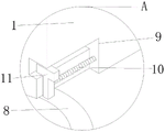
FIG. 2 is a schematic view of the bottom structure of the first input port of the present invention;
fig. 3 is an enlarged view of a portion a in fig. 2.
FIG. 4 is a schematic view of the shape of the clamping shell of the present invention;
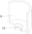
FIG. 5 is a schematic view of the bottom structure of the lid of the present invention;
FIG. 6 is a schematic view of the internal structure of the pressing sleeve of the present invention;
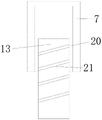
FIG. 7 is a schematic view of the internal structure of the pressing groove of the present invention;
fig. 8 is an enlarged view of fig. 7 at B.
Reference numerals are as follows: the box cover 1, the recovery box 2, the observation window 3, the first input opening 4, the second input opening 5, the pressing groove 6, the pressing sleeve 7, the clamping shell 8, the sliding groove 9, the first spring 10, the sliding block 11, the needle withdrawing block 12, the rotating rod 13, the torsion spring 14, the processing groove 15, the fixing block 16, the movable groove 17, the blade 18, the first limiting groove 19, the connecting rod 20, the spiral groove 21, the limiting plate 22, the second limiting groove 23 and the limiting rod 24.
Detailed Description
Reference will now be made in detail to the present preferred embodiments of the present invention, examples of which are illustrated in the accompanying drawings, wherein like reference numerals refer to like elements throughout.
In the description of the present invention, it should be understood that the orientation or positional relationship referred to in the description of the orientation, such as the upper, lower, front, rear, left, right, etc., is based on the orientation or positional relationship shown in the drawings, and is only for convenience of description and simplification of description, and does not indicate or imply that the device or element referred to must have a specific orientation, be constructed and operated in a specific orientation, and thus, should not be construed as limiting the present invention.
In the description of the present invention, greater than, less than, exceeding, etc. are understood as excluding the present numbers, and the above, below, inside, etc. are understood as including the present numbers. If there is a description of first and second for the purpose of distinguishing technical features only, this is not to be understood as indicating or implying a relative importance or implicitly indicating the number of technical features indicated or implicitly indicating the precedence of technical features indicated.
In the description of the present invention, unless otherwise specifically limited, terms such as set, installation, connection and the like should be understood in a broad sense, and those skilled in the art can reasonably determine the specific meanings of the above terms in the present invention by combining the specific contents of the technical solutions.
The first embodiment is as follows:
referring to fig. 1, the present invention provides a technical solution: general type medical needle device of cutting, including retrieving box 2, the surface of retrieving box 2 is provided with observation window 3, and then the setting through observation window 3, make medical staff observe the volume of retrieving the inside syringe needle of box 2, and then judge whether continue to use the device, the upper surface swing joint who retrieves box 2 has lid 1, setting through lid 1, seal retrieving box 2, prevent retrieving the unrestrained of the inside syringe needle of box 2, a first input 4 that runs through lid 1 is seted up to the upper surface of lid 1, the setting of first input 4, the syringe needle on the needle tubing is got rid of.
Referring to fig. 2-4, the lower surface of the box cover 1 is slidably connected with two clamping shells 8, the shapes of the two clamping shells 8 are matched with the needle ends of the needle tubes, the tops of the two clamping shells 8 are fixedly connected with "convex" shaped sliders 11, the bottom of the box cover 1 is provided with two "convex" shaped sliding grooves 9, the surfaces of the two sliders 11 are slidably connected with the inner walls of the two sliding grooves 9 respectively, and further the two clamping shells 8 are limited by the "convex" shaped sliding grooves 9 and the sliders 11, so that the two clamping shells 8 are mounted at the bottom of the box cover 1, the two clamping shells 8 cannot be separated from the box cover 1, the stability of the connection of the device is ensured, and the moving directions of the two clamping shells 8 are limited, so that the two clamping shells 8 can only move in the front and back directions at the bottom of the box cover 1, and cannot shift, so that the needle tubes are removed smoothly by the device, the opposite sides of the two sliders 11 are fixedly connected with first springs 10, one ends of the two first springs 10 far away from the two sliders 11 are fixedly connected with the inner walls of the two sliding grooves 9 respectively, the inner walls of the two clamping shells 8 are fixedly connected with two withdrawing blocks 12, and the needle withdrawing blocks are in the arc-shaped needle blocks 12.
Further, when the needle tube is withdrawn, the needle tube is inserted into the first feeding opening 4, the needle tube enters between the two clamping shells 8, the conical surface at the needle head of the needle tube is contacted with the two needle withdrawing blocks 12 along with the insertion of the needle tube, the two needle withdrawing blocks 12 are extruded, the two needle withdrawing blocks 12 run back to back, the two clamping shells 8 move back to back, the two first springs 10 are extruded, the needle tube can be continuously inserted between the two clamping shells 8 at the moment, when the lower end of the needle tube is contacted with the reducing parts of the two clamping shells 8, the conical surface at the needle head of the needle tube is separated from the two needle withdrawing blocks 12 at the moment, the two needle withdrawing blocks 12 move relatively under the elasticity of the two first springs 10, the nozzle parts of the two needle tubes are clamped, the needle tube is pulled out at the moment, the size of the two needle withdrawing blocks 12 is smaller than that of the conical surface of the needle head, the needle tube cannot be pulled out, the needle head can only be pulled out at the moment, the needle head is left to fall into the recovery box 2, the two needle withdrawing blocks 12 are opened, the potential safety hazards that the infection of the needle tube are effectively reduced or the bacteria are reduced.
Example two;
referring to fig. 5-8, on the basis of the first embodiment, a second input port 5 penetrating through the surface of the box cover 1 is formed on the surface of the box cover 1, the second input port 5 is provided for inputting a needle of an infusion tube, a fixing block 16 is fixedly connected to the lower surface of the box cover 1, a processing groove 15 penetrating through the surface of the fixing block 16 is formed on the surface of the fixing block 16, the processing groove 15 is located right below the second input port 5, so that the needle of the infusion tube can smoothly enter the processing groove 15 after being input into the second input port 5, preparation is made for cutting the needle of the infusion tube, a movable groove 17 penetrating through the surface of the fixing block 16 is formed on the surface of the fixing block 16, a pressing groove 6 penetrating through the surface of the box cover 1 is formed on the surface of the box cover 1, and a cutting mechanism is arranged inside the pressing groove 6.
The cutting mechanism comprises a pressing sleeve 7, the surface of the pressing sleeve 7 is in sliding connection with the surface of a pressing groove 6, the inner wall of the pressing sleeve 7 is in sliding connection with a rotating rod 13, the left side and the right side of the pressing sleeve 7 are fixedly connected with limiting rods 24, the two limiting rods 24 are lollipops, the left side and the right side of the inner wall of the pressing groove 6 are respectively provided with a first convex limiting groove 19, the inner walls of the two first limiting grooves 19 are respectively in sliding connection with the surfaces of the two limiting rods 24, the movement track of the pressing sleeve 7 is limited through the arrangement of the first limiting grooves 19 and the limiting rods 24, the pressing sleeve 7 can only slide up and down in the pressing groove 6, the pressing sleeve 7 cannot rotate in the pressing groove 6, the pressing sleeve 7 is guaranteed not to rotate along with the rotation of the rotating rod 13, the reasonable operation of the device is guaranteed, the surface of the rotating rod 13 is fixedly connected with a limiting plate 22, the surface of the limiting plate 22 is rotatably connected with the surface of the pressing groove 6, the inner wall of the pressing groove 6 is provided with a second limiting groove 23, the surface of the limiting plate 22 is slidably connected with the inner wall of the second limiting groove 23, and further, through the arrangement of the limiting plate 22 and the second limiting groove 23, the rotating rod 13 is erected inside the pressing groove 6 to support the rotating rod 13, and at the same time, the movement track of the rotating rod 13 is limited, so that the rotating rod 13 does not move up and down inside the pressing groove 6, thereby ensuring the smooth operation of the device, the surface of the rotating rod 13 is provided with a spiral groove 21, the inner wall of the spiral groove 21 is slidably connected with a connecting rod 20, the right end of the connecting rod 20 is fixedly connected with the inner wall of the pressing sleeve 7, the surface of the rotating rod 13 is movably sleeved with a torsion spring 14 fixedly connected with the surface of the rotating rod 13, one end of the torsion spring 14 far away from the rotating rod 13 is fixedly connected with the bottom of the box cover 1, the lower extreme fixedly connected with blade 18 of dwang 13, the surface of blade 18 and the inner wall sliding connection of activity groove 17, and then through the setting of activity groove 17, provide sufficient motion space for the circular motion of blade 18, and then avoided fixed block 16 to influence the condition of blade 18 motion, guaranteed the smooth operation of device.
When the needle on the infusion tube is removed, the pressing sleeve 7 is pressed, the inner wall of the pressing sleeve 7 slides and descends on the surface of the rotating rod 13, the connecting rod 20 is further used for extruding the inner wall of the spiral groove 21, the rotating rod 13 is further rotated, the blade 18 is further driven to rotate, the torsion spring 14 is driven to deform, the needle of the infusion tube is inserted into the second putting port 5, the needle of the infusion tube is completely separated from the processing groove 15, the infusion tube blocks the movable groove 17, the pressing sleeve 7 is not pressed, the rotating rod 13 is driven to rotate reversely under the elasticity of the torsion spring 14, the blade 18 is further driven to rotate reversely, the movable path of the blade 18 is blocked by the infusion tube, the blade 18 collides with the rotation of the blade 18, the infusion tube is further bent, and the upper end of the infusion tube is pulled by an operator, the needle head of the infusion tube is completely separated from the processing groove 15, the needle head of the infusion tube is flat and hard in texture, meanwhile, the pulling force of the infusion tube on the needle head is oblique pulling force, so that the upper end of the needle head is clamped in the processing groove 15, the infusion tube is in a relatively tight state, the blade 18 can cut off the infusion tube, the needle head of the infusion tube falls into the recovery box 2, the medical staff can cut and collect the needle head of the infusion tube at one time through the arrangement of the cutting mechanism, the medical staff does not need to cut off the needle head of the infusion tube first and then collect the needle head of the infusion tube, the treatment efficiency of the medical staff on the infusion tube is improved, the problem that liquid in the infusion tube splashes to the medical staff is solved, the medical staff does not need to pinch the needle head any more, and the possibility that the medical staff is pricked is reduced, the medical staff is protected, and the safety of the device in use is improved.
The working principle is as follows: when the needle on the infusion tube is removed, the pressing sleeve 7 is pressed, the inner wall of the pressing sleeve 7 slides and descends on the surface of the rotating rod 13, the connecting rod 20 is further used for extruding the inner wall of the spiral groove 21, the rotating rod 13 is further rotated, the blade 18 is further driven to rotate, the torsion spring 14 is driven to deform, the needle of the infusion tube is inserted into the second feeding port 5 at the moment, the pressing sleeve 7 is not pressed any more, the rotating rod 13 is further driven to rotate under the elastic force of the torsion spring 14, the blade 18 is further driven to rotate reversely, the moving path of the blade 18 is blocked by the infusion tube, the blade 18 can cut off the infusion tube, and the needle of the infusion tube falls into the recovery box 2.
The embodiments of the present invention have been described in detail with reference to the drawings, but the present invention is not limited to the embodiments, and various changes can be made within the knowledge of those skilled in the art without departing from the gist of the present invention.
Claims (9)
1. Medical needle device of cutting of general type, its characterized in that: including retrieving box (2), the upper surface swing joint who retrieves box (2) has lid (1), first mouth (4) of puting in that runs through lid (1) is seted up to the upper surface of lid (1), the lower surface sliding connection of lid (1) has two centre gripping shells (8), two centre gripping shell (8) shapes coincide with the syringe needle end of needle tubing, the equal fixedly connected with of inner wall of two centre gripping shells (8) moves back needle piece (12), two shapes that move back needle piece (12) are the arc, the second that runs through lid (1) surface is seted up on the surface of lid (1) is thrown in mouthful (5), pressing groove (6) that run through lid (1) surface are seted up on the surface of lid (1), the inside of pressing groove (6) is provided with cutting mechanism.
2. The universal medical needle shearing device as recited in claim 1, wherein: the surface of the recovery box (2) is provided with an observation window (3).
3. The universal medical needle shearing device as recited in claim 1, wherein: two the equal fixedly connected with in top of centre gripping shell (8) is slider (11) of "protruding" shape, and two spout (9) that are "protruding" shape are seted up to the bottom of lid (1), the surface of two slider (11) respectively with the inner wall sliding connection of two spout (9).
4. The universal medical needle shearing device as recited in claim 3, wherein: two the equal fixedly connected with first spring (10) of the back of the body side of slider (11), the one end difference fixed connection that two sliders (11) were kept away from in two first spring (10) is at the inner wall of two spout (9).
5. The universal medical needle shearing device as recited in claim 1, wherein: the lower fixed surface of lid (1) is connected with fixed block (16), and processing groove (15) that run through fixed block (16) surface are seted up on the surface of fixed block (16), and processing groove (15) are located second and put in mouthful (5) under, and movable groove (17) that run through fixed block (16) surface are seted up on the surface of fixed block (16).
6. The universal medical needle shearing device as recited in claim 5, wherein: cutting mechanism is including pressing cover (7), press the surface of cover (7) and the sliding surface connection who presses groove (6), the inner wall sliding connection who presses cover (7) has dwang (13), helicla flute (21) have been seted up on the surface of dwang (13), the inner wall sliding connection of helicla flute (21) has connecting rod (20), the right-hand member fixed connection of connecting rod (20) is at the inner wall that presses cover (7), lower extreme fixedly connected with blade (18) of dwang (13), the surface of blade (18) and the inner wall sliding connection of activity groove (17).
7. The universal medical needle shearing device as recited in claim 6, wherein: the surface activity of dwang (13) has cup jointed torsional spring (14) with the fixed surface of dwang (13) is connected, and the one end fixed connection that dwang (13) was kept away from in torsional spring (14) is in the bottom of lid (1).
8. The universal medical needle shearing device as recited in claim 6, wherein: the equal fixedly connected with restriction lever (24) of the left and right sides of pressing cover (7), the shape of two restriction levers (24) is the lollipop, presses the left and right sides of groove (6) inner wall and all offers first restriction groove (19) that are "protruding" shape, the inner wall of two first restriction grooves (19) respectively with the surperficial sliding connection of two restriction levers (24).
9. The universal medical needle shearing device as recited in claim 6, wherein: the fixed surface of dwang (13) is connected with limiting plate (22), and the surface of limiting plate (22) rotates with the surface that presses groove (6) to be connected, presses the inner wall of groove (6) to have seted up second restriction groove (23), and the surface of limiting plate (22) and the inner wall sliding connection of second restriction groove (23).
Priority Applications (1)
| Application Number | Priority Date | Filing Date | Title |
|---|---|---|---|
| CN202111562560.2A CN115245608B (en) | 2021-12-20 | 2021-12-20 | Universal medical needle shearing device |
Applications Claiming Priority (1)
| Application Number | Priority Date | Filing Date | Title |
|---|---|---|---|
| CN202111562560.2A CN115245608B (en) | 2021-12-20 | 2021-12-20 | Universal medical needle shearing device |
Publications (2)
| Publication Number | Publication Date |
|---|---|
| CN115245608A true CN115245608A (en) | 2022-10-28 |
| CN115245608B CN115245608B (en) | 2023-08-15 |
Family
ID=83698690
Family Applications (1)
| Application Number | Title | Priority Date | Filing Date |
|---|---|---|---|
| CN202111562560.2A Active CN115245608B (en) | 2021-12-20 | 2021-12-20 | Universal medical needle shearing device |
Country Status (1)
| Country | Link |
|---|---|
| CN (1) | CN115245608B (en) |
Citations (9)
| Publication number | Priority date | Publication date | Assignee | Title |
|---|---|---|---|---|
| US5356384A (en) * | 1993-02-02 | 1994-10-18 | Haber John P | Syringe with needle recapping system |
| CN207876529U (en) * | 2018-01-18 | 2018-09-18 | 柳州市妇幼保健院 | A kind of sharp disposable container with cutting function |
| CN208511646U (en) * | 2018-03-13 | 2019-02-19 | 云南省第三人民医院 | Improved type safe sharp instrument box |
| CN210644761U (en) * | 2019-06-13 | 2020-06-02 | 苏州市中医医院 | Single needle head collector |
| CN212490174U (en) * | 2020-04-21 | 2021-02-09 | 德阳市人民医院 | Shearing structure of sharp instrument box |
| CN212879582U (en) * | 2020-03-31 | 2021-04-06 | 重庆医科大学附属第二医院 | Medical sharp instrument collection box |
| CN112741940A (en) * | 2021-01-06 | 2021-05-04 | 赵泉宇 | Box is collected with sharp ware of arteriovenous syringe needle to infusion room |
| CN213968283U (en) * | 2020-12-09 | 2021-08-17 | 盐城市第一人民医院 | Medical treatment is with sharp weapon box |
| CN214778310U (en) * | 2021-01-20 | 2021-11-19 | 百色市人民医院 | Multifunctional sharps box |
-
2021
- 2021-12-20 CN CN202111562560.2A patent/CN115245608B/en active Active
Patent Citations (9)
| Publication number | Priority date | Publication date | Assignee | Title |
|---|---|---|---|---|
| US5356384A (en) * | 1993-02-02 | 1994-10-18 | Haber John P | Syringe with needle recapping system |
| CN207876529U (en) * | 2018-01-18 | 2018-09-18 | 柳州市妇幼保健院 | A kind of sharp disposable container with cutting function |
| CN208511646U (en) * | 2018-03-13 | 2019-02-19 | 云南省第三人民医院 | Improved type safe sharp instrument box |
| CN210644761U (en) * | 2019-06-13 | 2020-06-02 | 苏州市中医医院 | Single needle head collector |
| CN212879582U (en) * | 2020-03-31 | 2021-04-06 | 重庆医科大学附属第二医院 | Medical sharp instrument collection box |
| CN212490174U (en) * | 2020-04-21 | 2021-02-09 | 德阳市人民医院 | Shearing structure of sharp instrument box |
| CN213968283U (en) * | 2020-12-09 | 2021-08-17 | 盐城市第一人民医院 | Medical treatment is with sharp weapon box |
| CN112741940A (en) * | 2021-01-06 | 2021-05-04 | 赵泉宇 | Box is collected with sharp ware of arteriovenous syringe needle to infusion room |
| CN214778310U (en) * | 2021-01-20 | 2021-11-19 | 百色市人民医院 | Multifunctional sharps box |
Also Published As
| Publication number | Publication date |
|---|---|
| CN115245608B (en) | 2023-08-15 |
Similar Documents
| Publication | Publication Date | Title |
|---|---|---|
| CN110141730B (en) | A convenient crooked type dustbin of syringe needle for medical treatment | |
| CN115245608A (en) | General medical needle shearing device | |
| CN208511646U (en) | Improved type safe sharp instrument box | |
| CN215206661U (en) | Medical sharp instrument box | |
| CN108992180B (en) | Sharp instrument barrel and medical garbage can | |
| CN214908261U (en) | Sharp instrument box capable of quickly cutting off infusion tube | |
| CN209871352U (en) | Sharp instrument box | |
| CN110464477A (en) | A kind of divisible sharp disposable container of band elastic blade | |
| CN212729997U (en) | Medical sharp instrument collection box | |
| CN210408561U (en) | Preoperative pathological diagnosis puncture biopsy device for liver cancer | |
| CN211156951U (en) | Nursing car is retrieved to sharp weapon | |
| CN215351268U (en) | Collection device for critical care sharp tools | |
| CN219558331U (en) | Nursing appliance | |
| CN215821193U (en) | Edge tool box for accommodating clinical needles | |
| CN209884941U (en) | Sharp instrument box | |
| CN204507886U (en) | A kind of Medical sharps container | |
| CN219439448U (en) | Edge tool box | |
| CN213697996U (en) | Vomitus collection and sterilization device for hematology nursing | |
| CN216535534U (en) | Medical sharp instrument box | |
| CN213852527U (en) | Sharp ware section of thick bamboo that facilitates use | |
| CN218606614U (en) | Venous blood taking needle with needle head convenient to replace | |
| CN212291430U (en) | Medical safe sharp machine box | |
| CN218009806U (en) | Medical science is clinical with tumour biopsy sampling device | |
| CN219846823U (en) | Press separation type sharp instrument box | |
| CN219185342U (en) | Separator for sharp tool |
Legal Events
| Date | Code | Title | Description |
|---|---|---|---|
| PB01 | Publication | ||
| PB01 | Publication | ||
| SE01 | Entry into force of request for substantive examination | ||
| SE01 | Entry into force of request for substantive examination | ||
| TA01 | Transfer of patent application right | ||
| TA01 | Transfer of patent application right |
Effective date of registration: 20230720 Address after: Room 206, Floor 1, Building 5, Huaqing Garden, Tus Technopole, No. 100 Tianjiao Road, Qilin Science and Technology Innovation Park, Nanjing, Jiangsu 211100 Applicant after: Nanjing Lingyi Technology Co.,Ltd. Address before: 713300 group 2, Linping village, Linping Town, Xi county, Xianyang City, Shaanxi Province Applicant before: Wang Chao |
|
| GR01 | Patent grant | ||
| GR01 | Patent grant |