CN115235812A - Soil layer sampling device for building construction foundation detection - Google Patents
Soil layer sampling device for building construction foundation detection Download PDFInfo
- Publication number
- CN115235812A CN115235812A CN202111106800.8A CN202111106800A CN115235812A CN 115235812 A CN115235812 A CN 115235812A CN 202111106800 A CN202111106800 A CN 202111106800A CN 115235812 A CN115235812 A CN 115235812A
- Authority
- CN
- China
- Prior art keywords
- sampling
- component
- soil layer
- plate
- subassembly
- Prior art date
- Legal status (The legal status is an assumption and is not a legal conclusion. Google has not performed a legal analysis and makes no representation as to the accuracy of the status listed.)
- Granted
Links
Images


Classifications
-
- G—PHYSICS
- G01—MEASURING; TESTING
- G01N—INVESTIGATING OR ANALYSING MATERIALS BY DETERMINING THEIR CHEMICAL OR PHYSICAL PROPERTIES
- G01N1/00—Sampling; Preparing specimens for investigation
- G01N1/02—Devices for withdrawing samples
- G01N1/04—Devices for withdrawing samples in the solid state, e.g. by cutting
- G01N1/08—Devices for withdrawing samples in the solid state, e.g. by cutting involving an extracting tool, e.g. core bit
-
- E—FIXED CONSTRUCTIONS
- E02—HYDRAULIC ENGINEERING; FOUNDATIONS; SOIL SHIFTING
- E02D—FOUNDATIONS; EXCAVATIONS; EMBANKMENTS; UNDERGROUND OR UNDERWATER STRUCTURES
- E02D1/00—Investigation of foundation soil in situ
- E02D1/02—Investigation of foundation soil in situ before construction work
- E02D1/04—Sampling of soil
Abstract
The invention discloses a soil layer sampling device for building construction foundation detection, which comprises a positioning plate, supporting components, a pressing component and an excavating component, wherein a box body is arranged on the positioning plate, a plurality of groups of supporting components are arranged on the positioning plate in the circumferential direction of the box body, the supporting components are symmetrical relative to the box body, the pressing component is arranged in the box body, the excavating component is arranged at the bottom of the pressing component, the excavating component is used for crushing and tunneling a soil layer, the sampling component is arranged at the bottom of the excavating component, the sampling component is used for sampling and storing soil layer samples, the excavating component is driven by the pressing component to move downwards, the excavating component can send the sampling component to the ground below a certain depth, and the sampling component can be matched with the excavating component to rotate to collect and store soil samples at a target depth.
Description
Technical Field
The invention relates to the technical field of building construction, in particular to a soil layer sampling device for building construction foundation detection.
Background
From the point of view of field construction, the foundation can be divided into natural foundation and artificial foundation. The foundation is the bearing rock-soil bearing layer under the foundation. The natural foundation can meet the requirement of bearing all loads of the foundation in a natural state, a natural soil layer reinforced by people is not needed, the engineering cost is saved, and the foundation does not need manual treatment. The natural foundation is a natural soil layer which can be directly laid without treating the foundation. When the geological condition of the soil layer is better and the bearing capacity is stronger, a natural foundation can be adopted; under the condition of poor geological conditions, such as slope, sandy land or silt geology, or when the texture of the soil layer is good but the upper load is too large, in order to ensure that the foundation has enough bearing capacity, the foundation needs to be artificially reinforced, and in order to ensure the stability and the structural strength of the building, the soil layer of the foundation needs to be sampled and analyzed.
The soil layer sampling mainly adopts manual excavation to take a sample among the prior art, and the soil sample that the manual excavation can not guarantee to get all comes from the soil layer of target depth, leads to later stage experimental data inaccurate, can judge the soil composition of ground to have the error, can influence the intensity that the ground was built.
Disclosure of Invention
The invention aims to provide a soil layer sampling device for building construction foundation detection, which aims to solve the problems in the background technology.
In the description of the present invention, it should be noted that the terms "inside", "outside", "upper", "lower", and the like indicate orientations or positional relationships based on the orientations or positional relationships shown in the drawings or orientations or positional relationships that the products of the present invention conventionally use, which are merely for convenience in describing the present invention and simplifying the description, but do not indicate or imply that the referred device or element must have a specific orientation, be constructed in a specific orientation, or be operated, and thus, should not be construed as limiting the present invention. Furthermore, the terms "first," "second," and the like are used merely to distinguish one description from another, and are not to be construed as indicating or implying relative importance.
The embodiment of the invention discloses a soil layer sampling device for building construction foundation detection, which comprises a positioning plate, supporting assemblies, a pressing assembly and an excavating assembly, wherein a box body is arranged on the positioning plate, a plurality of groups of supporting assemblies are arranged on the positioning plate in the circumferential direction of the box body, the supporting assemblies are symmetrical relative to the box body, the pressing assembly is arranged in the box body, the excavating assembly is arranged at the bottom of the pressing assembly, the excavating assembly is used for crushing and tunneling a soil layer, the sampling assembly is arranged at the bottom of the excavating assembly, and the sampling assembly is used for sampling and storing soil layer samples.
Preferably, the supporting component includes supporting seat, backup pad, shop bolt and head rod, the supporting seat is located the bottom of locating plate, and fixed mounting has a first threaded rod on being provided with the supporting seat on the locating plate, and the hole normal running fit on first threaded rod and the locating plate rotates between supporting seat bottom and the backup pad to be connected with the head rod, runs through in the backup pad and is provided with the backup pad, and the backup pad inserts the ground and restricts the backup pad in subaerial position.
Preferably, the nut is installed in the one end screw thread rotation that the supporting seat was kept away from to first threaded rod, is provided with a pair of gasket between nut and the locating plate, gasket and first threaded rod normal running fit are provided with first spring between the gasket of both sides, first spring and first threaded rod normal running fit.
Preferably, the pushing assembly comprises a first telescopic rod and a push plate, the first telescopic rod is installed at the top in the box body, one side, far away from the top of the box body, of the first telescopic rod is connected with the push plate, guide plates are installed on two sides of the push plate, the guide plates are in sliding fit with the box body, guide sleeves are installed on two sides of the top of the first telescopic rod, guide rods are installed on the push plate, the guide rods are in sliding fit with the guide sleeves, and the digging assembly is installed at the bottom of the push plate.
Preferably, one side is provided with the through groove on the box, and the through groove both sides are provided with the scale mark, and sliding fit has the lug in the through groove, and the lug is installed on the push pedal, and the bottom of box is provided with the through hole, is connected with flexible bellows between through hole and the push pedal bottom.
Preferably, the cross section of the bump is diamond-shaped.
Preferably, it includes first spacing sleeve, installation disc, drilling rod and helical blade to excavate the subassembly, first spacing sleeve installs the bottom in the push pedal, second spacing sleeve is installed to the push pedal bottom, and second spacing sleeve is located first spacing sleeve inboard and coincides with first spacing sleeve axle center, install the axis of rotation on the installation disc, the axis of rotation is kept away from the one end of installation disc and is installed spacing disc, and spacing disc rotates and installs in second spacing sleeve, and first spacing sleeve is close to one side of installation disc and is embedded to be provided with the metal packing ring, and metal packing ring and first spacing sleeve normal running fit, sliding fit have circular slider in the second spacing sleeve, are connected with the second spring between circular slider and the push pedal, be provided with drive assembly in the first spacing sleeve, drive assembly is used for driving the axis of rotation, the drilling rod is installed to the bottom of installation disc, and helical blade is installed in the outside of drilling rod.
Preferably, drive assembly includes first motor, drive gear and ring gear, first motor is installed on the push pedal, and drive gear is installed to the output of first motor, and the ring gear is installed in the axis of rotation, drive gear and ring gear drive fit.
Preferably, the bottom of drilling rod is provided with the mounting hole, install flexible subassembly in the mounting hole, the sampling subassembly is installed to the bottom of flexible subassembly, and flexible subassembly is used for providing drive power in stretching out and retracting the mounting hole to the sampling subassembly.
Preferably, flexible subassembly includes second motor, third threaded rod, internal thread sleeve and mounting panel, the second motor is installed at the downthehole top of mounting panel, the third threaded rod is installed to the output of second motor, and fixed mounting has internal thread sleeve on the mounting panel, third threaded rod and internal thread sleeve screw thread normal running fit, both sides are provided with the spout in the mounting panel, and the sliding block is installed to the mounting panel both sides, and sliding block sliding fit is in the spout, and sampling component is installed to the bottom of mounting panel, the sealing ring is installed to the bottom of mounting panel, sliding fit has sampling component in the sealing ring.
Preferably, the sampling subassembly includes sampler barrel, second telescopic link and sampling box, the bottom at the mounting panel is installed to the sampler barrel, and fixed mounting has the baffle in the first fixed block, and the second telescopic link is installed at the top in the sampler barrel, and the free end and the baffle sliding fit of second telescopic link, a plurality of first fixed blocks of group are installed to the bottom circumference of second telescopic link, and the second telescopic link can guarantee first fixed block vertical lift in the sampler barrel with baffle sliding fit, there are a plurality of open slots of group bottom circumference even in the sampler barrel, fixed mounting has the swizzle on the sampling box, and the swizzle rotates and installs the top in the open slot, the second fixed block is installed to one side that the sampling box is located the sampler barrel, rotate through the second connecting rod between first fixed block and the second fixed block and be connected, and connect in the rotation of the flexible effect cooperation second connecting rod of second telescopic link.
Preferably, the opening of the sampling box faces in the horizontal direction.
Preferably, install the control module group in the first telescopic link, the control module group includes signal reception module and adjustment module, signal reception module is used for receiving the instruction that mobile terminal sent and sends the instruction for adjustment module, adjustment module is connected with the wiring end of first telescopic link, first motor, second motor and second telescopic link, and adjustment module is used for controlling the break-make between first telescopic link, first motor, second motor and the second telescopic link and the power.
Compared with the prior art, drive through the push down subassembly and excavate the subassembly and remove to the ground, can realize excavating the subassembly and deliver to the ground of certain degree of depth with the sampling component under, excavate the rotation of subassembly through the cooperation that opens and shuts of sampling component, can realize gathering the soil sample of target depth and preserve.
Drawings
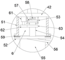
FIG. 1 is a schematic view of a soil sampling device for detecting a construction foundation according to the present invention.
FIG. 2 is a schematic diagram of a middle box of the soil sampling device for detecting the construction foundation.
FIG. 3 is a schematic view of an area A of a soil sampling device for detecting a foundation in a building construction according to the present invention.
FIG. 4 is a schematic cross-sectional view of a drill rod in the soil sampling device for foundation detection in building construction according to the present invention.
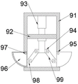
FIG. 5 is a schematic view of a sampling assembly of the soil sampling device for detecting the foundation in the construction of the present invention.
FIG. 6 is a schematic diagram of a control module in the soil sampling device for building construction foundation detection according to the present invention.
Reference numerals are as follows:
1-positioning plate, 2-box body, 21-through groove, 22-graduation line, 23-through hole, 24-flexible corrugated pipe, 3-supporting component, 31-supporting seat, 32-supporting plate, 33-positioning pin, 34-first connecting rod, 35-first threaded rod, 36-nut, 37-gasket, 38-first spring, 4-pressing component, 41-first telescopic rod, 42-push plate, 43-guide plate, 44-guide sleeve, 45-guide rod, 46-lug, 5-digging component, 51-first limiting sleeve, 52-mounting disk, 53-second limiting sleeve, 54-rotating shaft, 55-drill rod, 56-helical blade, 57-circular sliding block, 58-second spring, 59-metal washer, 6-driving component, 61-first motor, 62-driving gear, 63-toothed ring, 7-mounting hole, 8-telescopic component, 81-second motor, 82-sliding chute, 83-third threaded rod, 84-internal threaded sleeve, 85-mounting plate, 86-sliding block, 87-sealing ring, 9-sampling component, 91-sampling cylinder, 92-partition plate, 93-second telescopic rod, 94-first fixing block, 95-open slot, 96-sampling box, 97-rotating pin, 98-second fixing block, 99-second connecting rod, 10-control module, 101-signal receiving module, 102-adjusting module.
Detailed Description
In order to make the objects, technical solutions and advantages of the present invention more apparent, the present invention is described in further detail below with reference to the accompanying drawings and embodiments. It should be understood that the specific embodiments described herein are merely illustrative of the invention and are not intended to limit the invention.
Examples
As shown in fig. 1, a soil layer sampling device for building construction ground detection, including locating plate 1, supporting component 3, push down subassembly 4 and excavation subassembly 5, install box 2 on the locating plate 1, install a plurality of groups supporting component 3 around 2 circumference of box on the locating plate 1, supporting component 3 is symmetrical about box 2, can provide bradyseism and support for locating plate 1 when guaranteeing locating plate 1 stable balance, install push down subassembly 4 in the box 2, push down subassembly 4's bottom and install excavation subassembly 5, push down subassembly 4 can carry out lift adjustment to excavation subassembly 5 for excavation subassembly 5 is at relative locating plate 1 vertically direction rebound, pushes down subassembly 5 through pushing down subassembly 4 to the excavation of rotation, can make excavation subassembly 5 tunnel to the ground, excavation subassembly 5 is used for carrying out broken excavation to the soil layer, the bottom of excavation subassembly 5 is provided with sampling component 9, sampling component 9 is used for the sample and the storage to the soil layer sample, can drive sampling component 9 through excavation subassembly 5 after excavating subassembly 5 to the target depth and advance the soil layer to dig the sample the soil layer and take a sample.
Supporting component 3 includes supporting seat 31, backup pad 32, stop pin 33 and head rod 34, supporting seat 31 is located the bottom of locating plate 1, be provided with fixed mounting on the supporting seat 31 on the locating plate 1 and have first threaded rod 35, first threaded rod 35 and the hole normal running fit on the locating plate 1, it is connected with head rod 34 to rotate between supporting seat 31 bottom and the backup pad 32, it is provided with backup pad 32 to run through on the backup pad 32, backup pad 32 inserts ground and can restrict backup pad 32 subaerial position, through the turned angle of adjustment head rod 34 for supporting seat 31, can make level to locating plate 1 subaerial position, make locating plate 1 parallel with ground, it leads to locating plate 1 unstably to avoid base face pothole, make excavation component 5 shake when the tunnelling, easily cause the damage of excavation component 5, supporting component 3 for the symmetry setting of box 2 can support through head rod 34 when locating plate 1 takes place the vibrations, can not make the danger that locating plate 1 takes place to turn on one's side.
First threaded rod 35 is kept away from one end screw thread of supporting seat 31 and is rotated and install nut 36, is provided with a pair of gasket 37 between nut 36 and the locating plate 1, gasket 37 and first threaded rod 35 normal running fit, be provided with first spring 38 between the gasket 37 of both sides, first spring 38 and first threaded rod 35 normal running fit, under nut 36 and first threaded rod 35 screw thread normal running fit's locking effect, locating plate 1 and nut 36 are hugged closely to gasket 37, receive vibrations at locating plate 1 after, first spring 38 can carry out the energy storage buffering to the impact force of vibrations, reduce and excavate rocking of subassembly 5 and box 2, thereby guarantee to excavate the stable tunnelling of subassembly 5.
Push down subassembly 4 includes first telescopic link 41 and push pedal 42, first telescopic link 41 is installed at the box 2 internal top, one side that box 2 top was kept away from to first telescopic link 41 is connected with push pedal 42, and deflector 43 is installed to both sides on the push pedal 42, and deflector 43 and box 2 sliding fit can promote push pedal 42 when first telescopic link 41 is flexible and slide from top to bottom and do not take place to deflect in box 2, guide sleeve 44 is installed to first telescopic link 41 top both sides, installs guide bar 45 on the push pedal 42, and guide bar 45 and guide sleeve 44 sliding fit can provide the direction for the lift of push pedal 42 in box 2, and excavation subassembly 5 is installed to the bottom of push pedal 42, and under steady direction, the holding down force can make excavation subassembly 5 more stable carry out the tunnelling operation.
As shown in fig. 1 and 2, a through groove 21 is formed in one side of the box body 2, scale marks 22 are formed in two sides of the through groove 21, a projection 46 is in sliding fit in the through groove 21, the projection 46 is mounted on the push plate 42, the tunneling depth of the excavating component 5 can be reflected through the sliding of the projection 46 in the through groove 21, a through hole 23 is formed in the bottom of the box body 2, a flexible corrugated pipe 24 is connected between the through hole 23 and the bottom of the push plate 42, and the flexible corrugated pipe 24 can prevent soil blocks from entering the box body 2.
The cross section of the bump 46 is a diamond, and the scale marks 22 corresponding to the bump 46 can be conveniently and directly observed and recorded through sharp corners on two sides of the diamond.
As shown in fig. 1 and 3, the excavating component 5 includes a first limiting sleeve 51, a mounting disc 52, a drill rod 55 and a helical blade 56, the first limiting sleeve 51 is mounted at the bottom of the push plate 42, a second limiting sleeve 53 is mounted at the bottom of the push plate 42, the second limiting sleeve 53 is located inside the first limiting sleeve 51 and coincides with the axis of the first limiting sleeve 51, a rotating shaft 54 is mounted on the mounting disc 52, a limiting disc is mounted at one end of the rotating shaft 54 far from the mounting disc 52, the limiting disc is rotatably mounted in the second limiting sleeve 53, a metal washer 59 is embedded in one side of the first limiting sleeve 51 close to the mounting disc 52, and the metal washer 59 is rotatably matched with the first limiting sleeve 51, so as to reduce the resistance between the mounting disc 52 and the first limiting sleeve 51 and ensure that the mounting disc 52 is kept stable and does not deflect during the rotation, A circular sliding block 57 is matched with the second limiting sleeve 53 in a sliding mode, a second spring 58 is connected between the circular sliding block 57 and the push plate 42, the circular sliding block 57 can be tightly attached to a limiting disc under the support of the second spring 58, the shaking of the rotating shaft 54 can be reduced, a driving assembly 6 is arranged in the first limiting sleeve 51 and used for driving the rotating shaft 54 to rotate, a drill rod 55 is installed at the bottom of the mounting disc 52, a spiral blade 56 is installed on the outer side of the drill rod 55, the drill rod 55 can be driven to rotate under the driving of the driving assembly 6, and under the pressing effect of the pressing assembly 4, the drill rod 55 and the spiral blade 56 can rotate to crush soil layers of a foundation and convey soil blocks upwards, so that the drill rod 55 and the spiral blade 56 can continuously tunnel downwards.
As shown in fig. 4, a mounting hole 7 is formed in the bottom of the drill rod 55, a telescopic assembly 8 is installed in the mounting hole 7, a sampling assembly 9 is installed at the bottom of the telescopic assembly 8, and the telescopic assembly 8 is used for providing driving force for the sampling assembly 9 to extend out of and retract into the mounting hole 7.
The telescopic component 8 comprises a second motor 81, a third threaded rod 83, an internal threaded sleeve 84 and a mounting plate 85, the second motor 81 is mounted at the top in the mounting hole 7, the third threaded rod 83 is mounted at the output end of the second motor 81, the internal threaded sleeve 84 is fixedly mounted on the mounting plate 85, the third threaded rod 83 is in threaded rotation fit with the internal threaded sleeve 84, sliding blocks 86 are mounted on two sides of the mounting plate 85 in the mounting hole 7, the sliding blocks 86 are in sliding fit with the sliding grooves 82, guidance can be provided for lifting of the mounting plate 85 in the mounting hole 7, the sampling component 9 is mounted at the bottom of the mounting plate 85, the sampling component 85 stretches out of the mounting hole 7 from top to bottom, the sampling component 9 can be sampled and withdrawn from top to bottom, the sliding blocks 86 and the sliding blocks 82 can prevent the mounting plate 85 from rotating when stretching out of the mounting hole 7, the sampling component 9 does not rotate when stretching out, a sealing ring 87 is mounted at the bottom of the mounting hole 7, the sealing ring 87 is matched with the sampling component 9 in sliding, the sampling component 9 can prevent the sampling component 9 from entering the mounting hole 7 when the mounting hole 7, and the sampling component 9 can be prevented that the sampling depth of the sampling component 9 is different depths of the sampling component, and the sampling component is prevented from being mixed with the sampling depth in the sampling depth of the sampling component 9, and the sampling component 87, and the sampling depth of the sampling component is guaranteed in the sampling depth of the sampling component 9, and the sampling depth of the sampling component in the sampling component 9, and the sampling depth of the sampling component 9.
As shown in fig. 4 and 5, sampling subassembly 9 includes sampler barrel 91, second telescopic link 93 and sampling box 96, sampler barrel 91 is installed in the bottom of mounting panel 85, fixed mounting has baffle 92 in the first fixed block 94, second telescopic link 93 is installed at the top in the sampler barrel 91, the free end and the baffle 92 sliding fit of second telescopic link 93, a plurality of first fixed blocks 94 of group are installed to the bottom circumference of second telescopic link 93, second telescopic link 93 and baffle 92 sliding fit can guarantee that first fixed block 94 goes up and down in sampler barrel 91 perpendicularly, sampler barrel 91 bottom side circumference has a plurality of groups open slot 95 even, fixed mounting has rotating pin 97 on the sampling box 96, rotating pin 97 rotates and installs the top in open slot 95, second fixed block 98 is installed to the one side that sampling box 96 is located in sampler barrel 91, rotate through second connecting rod 99 between first fixed block 94 and the second fixed block 98 and connect, the rotation of telescopic action cooperation second connecting rod 99 at second telescopic link 93, can make sampler box 96 realize rotating in 95, realize promptly realizing stretching out the outside with sampler barrel 96 and with the sampler barrel 91 and with the sampling box 91 outside and can retrieve the sample depth cooperation of sample 96 and can accomplish the sample in sampler barrel 96 and sample depth and sample collection in sampling box 55, can be reached the sample depth cooperation.
As shown in fig. 5, the opening of the sampling box 96 faces the horizontal direction, so that soil samples of different depths are prevented from falling into the inside of the sampling box 96 to some extent.
As shown in fig. 1 and 6, a control module 10 is installed in the first telescopic rod 41, the control module 10 includes a signal receiving module 101 and an adjusting module 102, the signal receiving module 101 is configured to receive a command sent by the mobile terminal and send the command to the adjusting module 102, the adjusting module 102 is connected to terminals of the first telescopic rod 41, the first motor 61, the second motor 81 and the second telescopic rod 93, the adjusting module 102 is configured to control on/off of the first telescopic rod 41, the first motor 61, the second motor 81 and the second telescopic rod 93 and a power source, after the positioning plate 1 is fixed on a foundation by the support assembly 3, firstly, a command is sent to the signal receiving module 101, so that the adjusting module 102 connects the communication between the first telescopic rod 41 and the first motor 61 and the power source, so that the drill rod 55 and the helical blade 56 rotate and simultaneously crush and tunnel a foundation layer under the pressure of the push plate 42, the tunneling depth of the bottom of the drill rod 55 can be known by observing the convex block 46 and the scale mark 22, after the predetermined depth is reached, the mobile terminal sends an instruction to the signal receiving module 101, the adjusting module 102 disconnects the connection between the first telescopic rod 41 and the power supply and simultaneously connects the second motor 81 with the power supply, so that the sampling assembly 9 is pushed out of the mounting hole 7, after 10 seconds of pause, the connection between the second motor 81 and the power supply is disconnected and the second telescopic rod 93 is connected with the power supply, so that the sampling box 96 is pushed out of the sampling cylinder 91, soil samples are collected by matching the rotation of the drill rod 55, after 10 seconds of connection between the second telescopic rod 93 and the power supply, the connection between the second telescopic rod 93 and the power supply is reversely connected, so that the sampling box 96 is retracted into the sampling cylinder 91 to complete sampling, and the connection between the second motor 81 and the power supply is reversely connected, so that the sampling assembly 9 is retracted into the mounting hole 7, at this time, the first motor 61 is disconnected from the power supply, and the excavation component 5 is lifted upwards by connecting the first telescopic rod 41 with the power supply, so that the sampling component 9 is brought back to the ground to finish sampling.
The above description is only for the purpose of illustrating the preferred embodiments of the present invention and is not to be construed as limiting the invention, and any modifications, equivalents and improvements made within the spirit and principles of the present invention are intended to be included within the scope of the present invention.
The standard parts used in the invention can be purchased from the market, the special-shaped parts can be customized according to the description of the specification and the accompanying drawings, the specific connection mode of each part adopts conventional means such as bolts, rivets, welding and the like mature in the prior art, the machines, the parts and equipment adopt conventional models in the prior art, and the circuit connection adopts the conventional connection mode in the prior art, so that the detailed description is omitted.
It will be evident to those skilled in the art that the invention is not limited to the details of the foregoing illustrative embodiments, and that the present invention may be embodied in other specific forms without departing from the spirit or essential attributes thereof. The present embodiments are therefore to be considered in all respects as illustrative and not restrictive, the scope of the invention being indicated by the appended claims rather than by the foregoing description, and all changes which come within the meaning and range of equivalency of the claims are therefore intended to be embraced therein. Any reference sign in a claim should not be construed as limiting the claim concerned.
Furthermore, it should be understood that although the present description refers to embodiments, not every embodiment may contain only a single embodiment, and such description is for clarity only, and those skilled in the art should integrate the description, and the embodiments may be combined as appropriate to form other embodiments understood by those skilled in the art.
Claims (9)
1. The utility model provides a construction ground detects uses soil layer sampling device, includes locating plate (1), supporting component (3), pushes down subassembly (4) and excavates subassembly (5), its characterized in that, install box (2) on locating plate (1), install a plurality of groups supporting component (3) around box (2) circumference on locating plate (1), supporting component (3) are about box (2) symmetry, install in box (2) and push down subassembly (4), the bottom of pushing down subassembly (4) is installed and is excavated subassembly (5), excavates subassembly (5) and is used for carrying out broken tunnelling to the soil layer, and the bottom of excavating subassembly (5) is provided with sampling component (9), and sampling component (9) are used for the sample and the storage to the soil layer sample, the bottom of excavating subassembly (5) is provided with mounting hole (7), install flexible subassembly (8) in mounting hole (7), sampling component (9) are installed to the bottom of flexible subassembly (8), and flexible subassembly (8) are used for providing drive power in stretching out and withdrawal mounting hole (7) to sampling component (9).
2. The soil layer sampling device for building construction foundation detection according to claim 1, wherein the support assembly (3) comprises a support seat (31), a support plate (32), a positioning pin (33) and a first connecting rod (34), the support seat (31) is located at the bottom of the positioning plate (1), the positioning plate (1) is provided with the first threaded rod (35) fixedly mounted on the support seat (31), the first threaded rod (35) is in rotating fit with a hole in the positioning plate (1), the first connecting rod (34) is rotatably connected between the bottom of the support seat (31) and the support plate (32), the support plate (32) penetrates through the support plate (32), and the position of the support plate (32) on the ground is limited by the insertion of the support plate (32).
3. The soil layer sampling device for building construction foundation detection according to claim 2, wherein a nut (36) is rotatably mounted on one end of the first threaded rod (35) far away from the support seat (31), a pair of gaskets (37) is arranged between the nut (36) and the positioning plate (1), the gaskets (37) are rotatably matched with the first threaded rod (35), a first spring (38) is arranged between the gaskets (37) on two sides, and the first spring (38) is rotatably matched with the first threaded rod (35).
4. The soil layer sampling device for building construction foundation detection of claim 3, wherein the pushing component (4) comprises a first telescopic rod (41) and a push plate (42), the first telescopic rod (41) is installed at the inner top of the box body (2), one side of the first telescopic rod (41) far away from the top of the box body (2) is connected with the push plate (42), guide plates (43) are installed on two sides of the push plate (42), the guide plates (43) are in sliding fit with the box body (2), guide sleeves (44) are installed on two sides of the top of the first telescopic rod (41), guide rods (45) are installed on the push plate (42), the guide rods (45) are in sliding fit with the guide sleeves (44), and the digging component (5) is installed at the bottom of the push plate (42).
5. The soil layer sampling device for detecting the building construction foundation as claimed in claim 4, wherein a through groove (21) is formed in one side of the box body (2), scale marks (22) are formed in two sides of the through groove (21), a convex block (46) is arranged in the through groove (21) in a sliding fit mode, the convex block (46) is installed on the push plate (42), a through hole (23) is formed in the bottom of the box body (2), and a flexible corrugated pipe (24) is connected between the through hole (23) and the bottom of the push plate (42).
6. The soil layer sampling device for building construction foundation detection according to claim 5, wherein the excavating component (5) comprises a first limiting sleeve (51), a mounting disc (52), a drill rod (55) and a helical blade (56), the first limiting sleeve (51) is mounted at the bottom of the push plate (42), a second limiting sleeve (53) is mounted at the bottom of the push plate (42), the second limiting sleeve (53) is located on the inner side of the first limiting sleeve (51) and coincides with the axis of the first limiting sleeve (51), a rotating shaft (54) is mounted on the mounting disc (52), one end of the rotating shaft (54) far away from the mounting disc (52) is mounted with the limiting disc, the limiting disc is rotatably mounted in the second limiting sleeve (53), a metal washer (59) is embedded in one side of the first limiting sleeve (51) close to the mounting disc (52), the metal washer (59) is rotatably fitted with the first limiting sleeve (51), a circular slider (57) is slidably fitted in the second limiting sleeve (53), a second spring (58) is connected between the circular slider (57) and the push plate (42), a driving component (6) is mounted in the driving component (6), and a driving component (54) is mounted in the rotating disc (52), the outer side of the drill rod (55) is provided with a helical blade (56).
7. The soil layer sampling device for building construction ground detects according to claim 6, characterized in that, flexible subassembly (8) includes second motor (81), third threaded rod (83), internal thread sleeve (84) and mounting panel (85), top in mounting hole (7) is installed to second motor (81), third threaded rod (83) is installed to the output of second motor (81), and fixed mounting has internal thread sleeve (84) on mounting panel (85), third threaded rod (83) and internal thread sleeve (84) screw thread normal running fit, both sides are provided with spout (82) in mounting hole (7), and sliding block (86) are installed to mounting panel (85) both sides, and sliding block (86) sliding fit is in spout (82), and sampling component (9) are installed to the bottom of mounting panel (85), sealing ring (87) are installed to the bottom of mounting hole (7), sliding fit has sampling component (9) in sealing ring (87).
8. The soil layer sampling device for construction foundation inspection as recited in claim 7, the sampling component (9) comprises a sampling cylinder (91), a second telescopic rod (93) and a sampling box (96), the sampling cylinder (91) is installed at the bottom of the installation plate (85), the partition plate (92) is fixedly installed in the first fixing block (94), the second telescopic rod (93) is installed at the top in the sampling cylinder (91), the free end of the second telescopic rod (93) is in sliding fit with the partition plate (92), a plurality of groups of first fixing blocks (94) are installed at the periphery of the bottom of the second telescopic rod (93), the second telescopic rod (93) is in sliding fit with the partition plate (92) to ensure that the first fixing block (94) can vertically lift in the sampling cylinder (91), the side surface of the bottom of the sampling cylinder (91) is circumferentially provided with a plurality of groups of open slots (95), the sampling box (96) is fixedly provided with a rotating pin (97), the rotating pin (97) is rotatably arranged at the top in the open slot (95), a second fixing block (98) is arranged on one side of the sampling box (96) positioned in the sampling cylinder (91), the first fixed block (94) is rotationally connected with the second fixed block (98) through a second connecting rod (99), the telescopic action of the second telescopic rod (93) is matched with the rotary connection of the second connecting rod (99).
9. The soil layer sampling device for construction foundation detection as recited in claim 8, wherein an opening of the sampling box (96) is directed in a horizontal direction.
Priority Applications (1)
| Application Number | Priority Date | Filing Date | Title |
|---|---|---|---|
| CN202111106800.8A CN115235812B (en) | 2021-09-22 | 2021-09-22 | Soil layer sampling device for building construction foundation detection |
Applications Claiming Priority (1)
| Application Number | Priority Date | Filing Date | Title |
|---|---|---|---|
| CN202111106800.8A CN115235812B (en) | 2021-09-22 | 2021-09-22 | Soil layer sampling device for building construction foundation detection |
Publications (2)
| Publication Number | Publication Date |
|---|---|
| CN115235812A true CN115235812A (en) | 2022-10-25 |
| CN115235812B CN115235812B (en) | 2022-11-29 |
Family
ID=83665806
Family Applications (1)
| Application Number | Title | Priority Date | Filing Date |
|---|---|---|---|
| CN202111106800.8A Active CN115235812B (en) | 2021-09-22 | 2021-09-22 | Soil layer sampling device for building construction foundation detection |
Country Status (1)
| Country | Link |
|---|---|
| CN (1) | CN115235812B (en) |
Cited By (3)
| Publication number | Priority date | Publication date | Assignee | Title |
|---|---|---|---|---|
| CN115597648A (en) * | 2022-12-14 | 2023-01-13 | 青岛地质工程勘察院(青岛地质勘查开发局)(Cn) | Portable geological disaster monitoring device |
| CN116593205A (en) * | 2023-05-17 | 2023-08-15 | 陕西师范大学 | Soil detector |
| CN117230772A (en) * | 2023-11-14 | 2023-12-15 | 徐州大通建设集团有限公司 | On-spot soil material sampling equipment is used in municipal road construction |
Citations (6)
| Publication number | Priority date | Publication date | Assignee | Title |
|---|---|---|---|---|
| CN108871853A (en) * | 2018-08-28 | 2018-11-23 | 杜鑫 | A kind of construction deep soil sampler |
| CN210108753U (en) * | 2019-03-22 | 2020-02-21 | 江苏国润云天工程项目管理有限公司 | Soil layer distribution detection equipment convenient to sample |
| CN210863206U (en) * | 2019-08-16 | 2020-06-26 | 淮安翔宇环境检测技术有限公司 | A sampling device for soil detection |
| CN211122052U (en) * | 2019-09-11 | 2020-07-28 | 中国地质大学(北京) | Geotechnical sampling device in geotechnical engineering |
| CN211978373U (en) * | 2020-05-20 | 2020-11-20 | 郭广华 | Coal mine geological drilling sampling device |
| CN212674474U (en) * | 2020-04-13 | 2021-03-09 | 杨娇 | Sampling device for deep soil detection |
-
2021
- 2021-09-22 CN CN202111106800.8A patent/CN115235812B/en active Active
Patent Citations (6)
| Publication number | Priority date | Publication date | Assignee | Title |
|---|---|---|---|---|
| CN108871853A (en) * | 2018-08-28 | 2018-11-23 | 杜鑫 | A kind of construction deep soil sampler |
| CN210108753U (en) * | 2019-03-22 | 2020-02-21 | 江苏国润云天工程项目管理有限公司 | Soil layer distribution detection equipment convenient to sample |
| CN210863206U (en) * | 2019-08-16 | 2020-06-26 | 淮安翔宇环境检测技术有限公司 | A sampling device for soil detection |
| CN211122052U (en) * | 2019-09-11 | 2020-07-28 | 中国地质大学(北京) | Geotechnical sampling device in geotechnical engineering |
| CN212674474U (en) * | 2020-04-13 | 2021-03-09 | 杨娇 | Sampling device for deep soil detection |
| CN211978373U (en) * | 2020-05-20 | 2020-11-20 | 郭广华 | Coal mine geological drilling sampling device |
Cited By (6)
| Publication number | Priority date | Publication date | Assignee | Title |
|---|---|---|---|---|
| CN115597648A (en) * | 2022-12-14 | 2023-01-13 | 青岛地质工程勘察院(青岛地质勘查开发局)(Cn) | Portable geological disaster monitoring device |
| CN115597648B (en) * | 2022-12-14 | 2023-03-07 | 青岛地质工程勘察院(青岛地质勘查开发局) | Portable geological disaster monitoring device |
| CN116593205A (en) * | 2023-05-17 | 2023-08-15 | 陕西师范大学 | Soil detector |
| CN116593205B (en) * | 2023-05-17 | 2024-03-08 | 陕西师范大学 | Soil detector |
| CN117230772A (en) * | 2023-11-14 | 2023-12-15 | 徐州大通建设集团有限公司 | On-spot soil material sampling equipment is used in municipal road construction |
| CN117230772B (en) * | 2023-11-14 | 2024-01-23 | 徐州大通建设集团有限公司 | On-spot soil material sampling equipment is used in municipal road construction |
Also Published As
| Publication number | Publication date |
|---|---|
| CN115235812B (en) | 2022-11-29 |
Similar Documents
| Publication | Publication Date | Title |
|---|---|---|
| CN115235812B (en) | Soil layer sampling device for building construction foundation detection | |
| CN204002822U (en) | A kind of push pipe pipe curtain construction equipment | |
| CN111764855A (en) | Near-horizontal continuous directional coring advanced geological exploration system and method | |
| CN103046866B (en) | Universal rotating drilling machine | |
| CN110376028A (en) | A kind of coal mine coal-bed gas sample acquisitions device | |
| JPH0886186A (en) | Rock drilling device | |
| CN210105743U (en) | Excavation device for drainage well in municipal engineering road maintenance ponding area | |
| CN218324735U (en) | Multifunctional drilling machine for soil remediation | |
| JP4014975B2 (en) | Lightweight boring equipment | |
| CN115711764A (en) | Compactness detects sampling device | |
| CN212177035U (en) | Crawler-type core drilling machine with small-inclination drilling function | |
| CN112096279B (en) | Electric power engineering surveys device | |
| CN210264506U (en) | Drilling rig for geotechnical engineering investigation | |
| CN210264510U (en) | Novel vehicle-mounted rotary drilling rig for railway track with power | |
| CN111395958A (en) | Crawler-type core drilling machine with small-inclination drilling function | |
| CN220748163U (en) | Spiral drilling type rock-soil drilling device | |
| CN215714520U (en) | Highway compactness test detection equipment | |
| CN217652683U (en) | Anti-deviation device for rock and soil exploration drilling | |
| CN220794655U (en) | Geological survey ware is used in colliery measurement | |
| CN214952255U (en) | Weak foundation soil sampling device | |
| CN219412510U (en) | Tilting device applied to iron roughneck | |
| CN215177694U (en) | Ground settlement depth monitoring devices | |
| CN115839437B (en) | Construction method for jacking pipe of underground rainwater and sewage pipeline | |
| CN218444533U (en) | Geotechnical engineering survey equipment | |
| CN220689929U (en) | Pipe burying device for mining blasting |
Legal Events
| Date | Code | Title | Description |
|---|---|---|---|
| PB01 | Publication | ||
| PB01 | Publication | ||
| SE01 | Entry into force of request for substantive examination | ||
| SE01 | Entry into force of request for substantive examination | ||
| GR01 | Patent grant | ||
| GR01 | Patent grant |