Disclosure of Invention
The invention aims to overcome the defect that the prior art can not automatically detect the resistance of electric melting pipe fittings with different sizes, and provides equipment for automatically adjusting and detecting the resistance of the electric melting pipe fittings.
In order to solve the technical problems, the technical scheme adopted by the invention is as follows:
the utility model provides an automatic adjust equipment that detects electric smelting pipe fitting resistance, include the operation panel, connect in the operation panel and be used for a plurality of electric smelting pipe fittings row and the feed mechanism who conveys one by one, connect in the operation panel and be used for fixed and rotatory electric smelting pipe fitting's longitudinal register mechanism, connect in the operation panel and be used for cooperating the vertical resistance measuring mechanism that longitudinal register mechanism surveyed electric smelting pipe fitting resistance, connect in the operation panel and be used for receiving the electric smelting pipe fitting of feed mechanism conveying and convey to longitudinal register mechanism's longmen feed mechanism, longmen feed mechanism sets up at the feed mechanism terminal, longitudinal register mechanism and vertical resistance measuring mechanism set up longmen feed mechanism terminal.
According to the equipment for automatically adjusting and detecting the resistance of the electric melting pipe fittings, the electric melting pipe fittings with any size can be arranged in a line under the action of the material distribution mechanism and are transmitted to the gantry feeding mechanism arranged at the tail end of the material distribution mechanism one by one, the gantry feeding mechanism transmits the electric melting pipe fittings with any size to the longitudinal positioning mechanism arranged at the tail end of the gantry feeding mechanism, the longitudinal positioning mechanism firstly fixes the electric melting pipe fittings with any size in the axial direction and then rotates a binding post of the electric melting pipe fittings to the working surface of the vertical resistance measuring mechanism, and the vertical resistance measuring mechanism can measure the resistance of the electric melting pipe fittings with any size, so that the operation of automatically adjusting and detecting the resistance of the electric melting pipe fittings with any size is completed; the automatic resistance detection device solves the technical problem that the automatic resistance detection can not be carried out on the electric melting pipe fittings with different sizes in the prior art, is suitable for carrying out automatic resistance detection on the electric melting pipe fittings with various sizes, and has the product advantages of high automation, high intelligence and high integration and wide application prospect.
Further, feed mechanism is including connecting in the first conveyer belt that the operation panel is used for conveying electric smelting pipe fitting, setting in first conveyer belt traffic direction both sides and be used for contacting and spacing electric smelting pipe fitting's striker plate, connect in the striker plate be used for blockking electric smelting pipe fitting and be equipped with first cylinder, fixed connection of first push rod draw close and divided first drive arrangement in the operation panel and be used for controlling the striker plate, first push rod sets up in the one side that is close to electric smelting pipe fitting, the striker plate is connected in first drive arrangement's output. The first conveyor belt is used for conveying the electric melting pipe fittings, the contact limiting effect of the striker plates on the two sides of the conveyor belt on the electric melting pipe fittings is matched, the electric melting pipe fittings are arranged in a straight line in the striker plates on the two sides for conveying, and the first driving device can drive and adjust the distance between the striker plates on the two sides aiming at the electric melting pipe fittings with different sizes; first cylinder setting can follow the striker plate and adjust and play the effect of blockking to electric smelting pipe fitting together on the striker plate, blocks when first push rod stretches out that electric smelting pipe fitting on the first conveyer belt advances, returns when first push rod and goes back electric smelting pipe fitting on the first conveyer belt and continue to advance, after an electric smelting pipe fitting passes through first cylinder, first push rod stretches out once more and blocks electric smelting pipe fitting thereafter, has realized the conveying one by one of electric smelting pipe fitting, has simple structure convenient to use's advantage.
Further, the first driving device comprises a first fixing frame and a second fixing frame which are fixed on the operating platform and are respectively arranged on two sides of the first conveying belt in the running direction, a first synchronizing wheel rotationally connected to the first fixing frame, a first motor connected to the first fixing frame and used for driving the first synchronizing wheel to rotate, a second synchronizing wheel rotationally connected to the second fixing frame, a first synchronizing belt surrounding the outer walls of the first synchronizing wheel and the second synchronizing wheel, a first fastening piece connected to one side of the first synchronizing belt and close to the first fixing frame, a second fastening piece connected to the other side of the first synchronizing belt and close to one side of the second fixing frame, a first connecting frame connected to the first fastening piece and a second connecting frame connected to the second fastening piece, the first synchronizing wheel is connected to an output shaft of the first motor, and the first connecting frame and the second connecting frame are respectively connected to one side of the material blocking plate far away from the electric melting pipe fitting. Because a certain distance is reserved between the first synchronizing wheel and the second synchronizing wheel, when the first synchronizing belt is driven to rotate, the first synchronizing belt is divided into two average sections which move in opposite directions, because the first fastening piece is connected to one side of the first synchronizing belt and close to one side of the first fixing frame, the second fastening piece is connected to the other side of the first synchronizing belt and close to one side of the second fixing frame, and the first fastening piece and the second fastening piece both move in opposite directions no matter the first synchronizing belt is driven to rotate clockwise or anticlockwise, the first fastening piece and the second fastening piece can respectively drive the first connecting frame and the second connecting frame to simultaneously approach to each other and separate from each other by controlling the forward and reverse rotation of the first synchronizing wheel through the first motor, and therefore the striker plates can approach to each other and separate from each other.
Further, vertical resistance measuring mechanism includes sliding connection in the fixing base of operation panel, be used for driving fixing base slip second drive arrangement, be equipped with the testing arrangement who is used for inserting the probe of terminal, be used for controlling the telescoping device of testing arrangement concertina movement, fixed connection in the fixing base and be used for controlling elevating gear and fixed connection in the fixing base and set up the test baffle that is used for butt terminal outer wall between testing arrangement and longitudinal positioning mechanism, the fixing base is connected in second drive arrangement's output, the gliding direction of the relative operation panel of fixing base is on a parallel with testing arrangement's flexible direction, testing arrangement connects in the output of telescoping device, the telescoping device is connected in elevating gear's output, testing arrangement's flexible direction perpendicular to elevating direction, the horizontal distance that the test baffle is used for one side in butt terminal axle center is the radius of terminal. Can adjust the distance between vertical resistance measuring mechanism and the electric smelting pipe fitting according to the electric smelting pipe fitting control second drive arrangement drive fixing base of unidimensional slip on the operation panel, after longitudinal positioning mechanism fixes the electric smelting pipe fitting and rotatory when the contact of terminal outer wall is on the test baffle, the test baffle makes electric smelting pipe fitting stall to the effect that blocks of terminal, because the horizontal distance that the axle center of probe is used for butt terminal to one side of test baffle is the radius of terminal, the testing arrangement who is equipped with the probe that is used for inserting the terminal can move to the position of probe axle center and terminal axle center coincidence under elevating gear's drive, telescoping device drive testing arrangement stretches out, the probe inserts test resistance in the terminal, telescoping device drive testing arrangement contracts after accomplishing the test, accomplish the test resistance operation, have the advantage that degree of automation and intellectuality are high.
Further, testing arrangement is including connecting in the axle bed of telescoping device output, sliding connection in the axle bed and be used for contacting the stop collar of terminal outer wall and setting up the spring between stop collar and axle bed, probe connection is in the axle bed and sets up under the stop collar, one side that the stop collar is close to the probe is equipped with the sensor that is used for contacting the terminal outer wall, the distance of sensor to probe axle center is the radius of terminal. The sensor is arranged on one side of the limiting sleeve close to the probe and used for sensing whether the sensor contacts the outer wall of the binding post or not; because the stop collar is arranged right above the probe and is in sliding connection with the shaft seat, the stop collar can abut against the outer wall of the electric melting pipe fitting when the probe is inserted into the wiring terminal, and the stop collar returns to the original position under the action of the spring when the probe retracts, so that the action of detecting the resistance is completed.
Furthermore, the longitudinal positioning mechanism comprises a clamping device which is rotatably connected to the operating platform and used for axially fixing the electric melting pipe fitting, and a third driving device for driving the clamping device to rotate, the clamping device is connected to the output end of the third driving device, and the rotating shaft of the clamping device is superposed with the moving plane of the probe and is vertical to the axis of the probe. Because the rotating shaft of the clamping device coincides with the motion plane where the probe is located and is perpendicular to the axis of the probe, after the electric melting pipe fitting is axially fixed through the clamping device, the axis of the wiring terminal coincides with the motion plane where the probe is located and is parallel to the axis of the probe after the electric melting pipe fitting is rotated for a certain angle, and the probe can be inserted into the wiring terminal after simple planar motion is carried out in the motion plane of the probe.
Further, clamping device is including connecting in the axis of rotation of third drive arrangement output, the clamping platform of a plurality of spouts has evenly been seted up in axis of rotation and radial to the axial connection, sliding connection just is used for contacting the clamp arm of electric smelting pipe fitting inner wall in the spout, rotate to connect and keep away from the gyro wheel of electric smelting pipe fitting one side in the clamp arm, set up the race that is used for restricting gyro wheel up-and-down motion in the spout below, the axial connection is kept away from the rotor arm of clamp arm one side in the gyro wheel, set up between gyro wheel and third drive arrangement axial rotation connect in axis of rotation and radial distribution have the dish of cutting apart of a plurality of arc guide slots, be used for the drive to cut apart a set pivoted revolving cylinder, gyro wheel sliding connection is in the race, rotor arm sliding connection is in the guide way, the one end of spout is close to the center of clamping platform just the other end of spout is kept away from the center of clamping platform, the one end of guide slot is close to the center of cutting apart the dish just the other end of guide slot keeps away from the center of cutting apart the dish, cut apart the dish and connect in revolving cylinder's output shaft. The rotating shaft drives the electric melting pipe fittings placed on the clamping table to rotate, and the clamping arms play a role in fixing by applying acting force on the inner walls of the electric melting pipe fittings; because the one end of cutting apart a plurality of arc guide ways of dish radial distribution is close to the center of cutting apart the dish just the center of cutting apart the dish is kept away from to the other end of guide way, so when the dish rotates is cut apart in the revolving cylinder drive, sliding connection can slide in the guide way under the rotation effect of cutting apart the dish to the rotor arm in the guide way, because the rotor arm is connected in sliding connection's gyro wheel in the wheel inslot, the rotor arm can drive the gyro wheel at the wheel inslot radial direction slip in the guide way radial displacement, thereby drive the tight arm of clamp of being connected with the gyro wheel and slide in the spout, play the elasticity effect to electric smelting pipe fitting.
Further, longmen feed mechanism is including being fixed in the portal frame of operation panel, sliding connection in portal frame and set up the first material loading arm between first conveyer belt end and longitudinal positioning mechanism, connect in first material loading arm and be used for driving the gliding fourth drive arrangement of first material loading arm, connect in first material loading arm and be equipped with the second cylinder of second push rod and connect in second push rod tip and be used for snatching the first clamping jaw cylinder of electric smelting pipe fitting, first material loading arm is connected in the output shaft of fourth drive arrangement, the second push rod sets up in the one side that is close to electric smelting pipe fitting. First material loading arm can be at first conveyer belt end and longitudinal positioning mechanism relative portal frame slip down under fourth drive arrangement's drive effect, connects in the second cylinder of first material loading arm and makes the first clamping jaw cylinder of connecting at second push rod tip be close to the terminal electric smelting pipe fitting of first conveyer belt through stretching out the second push rod, and first clamping jaw cylinder can snatch electric smelting pipe fitting through pressing from both sides tight contact electric smelting pipe fitting outer wall.
The gantry feeding mechanism further comprises a second feeding arm, a fifth driving device, a third air cylinder and a second clamping jaw air cylinder, the second feeding arm is connected with the second feeding arm in a sliding mode and is provided with a third push rod, the second clamping jaw air cylinder is connected to the end portion of the third push rod and is used for grabbing the electric melting pipe fittings, the second feeding arm is connected to an output shaft of the fifth driving device, and the third push rod is arranged on one side close to the electric melting pipe fittings. The removing mechanism is used for receiving the electric melting pipe fittings transmitted by the gantry feeding mechanism and removing unqualified products; the second feeding arm can slide relative to the portal frame between the longitudinal positioning mechanism and the removing mechanism under the driving action of the fifth driving device, the third cylinder connected to the second feeding arm enables the second clamping jaw cylinder connected to the end part of the third push rod to be close to the electric melting pipe fitting of the longitudinal positioning mechanism through extending out the third push rod, and the second clamping jaw cylinder can grab the electric melting pipe fitting through clamping and contacting the outer wall of the electric melting pipe fitting.
Further, get rid of the mechanism including connect in the operation panel and be used for receiving the second conveyer belt of the electric smelting pipe fitting that second clamping jaw cylinder conveyed, set up the frame of getting rid of in second conveyer belt top, sliding connection get rid of the frame and be used for butt electric smelting pipe fitting get rid of the board, connect in the board and be used for driving the gliding sixth drive arrangement of board of getting rid of, rotate and connect in the frame of getting rid of and be equipped with the fourth cylinder of fourth push rod, rotate and connect in the check plate of getting rid of frame and fourth push rod tip, the slip direction perpendicular to second conveyer belt of the relative frame of getting rid of the board, the fourth cylinder with get rid of the frame, fourth push rod and check plate and the rotation axis perpendicular to conveyer belt traffic direction between the frame of getting rid of the board. The electric melting pipe fittings conveyed by the second clamping jaw air cylinder are firstly placed on the second conveying belt, the qualified electric melting pipe fittings pass through the qualified plate, and the sliding direction of the removing plate relative to the removing frame is driven by the sixth driving device to be vertical to the running direction of the second conveying belt, so the unqualified electric melting pipe fittings can move to be vertical to the running direction of the second conveying belt under the pushing of the removing plate; because the rotating shafts between the fourth cylinder and the removing frame, between the fourth push rod and the qualified plate and between the qualified plate and the removing frame are perpendicular to the running direction of the conveyor belt, when the fourth cylinder controls the fourth push rod to retract, the qualified plate is lifted, and the electric melting pipe fitting can smoothly pass through.
Compared with the prior art, the invention has the beneficial effects that:
the equipment for automatically adjusting and detecting the resistance of the electric melting pipe fittings adopts a production line mode, can continuously and automatically detect the resistance of large-batch electric melting pipe fittings, is suitable for automatically detecting the resistance of electric melting pipe fittings with various sizes, can automatically stock qualified electric melting pipe fittings and simultaneously remove unqualified electric melting pipe fittings, and has the product advantages of high automation, high intelligence and high integration and wide application prospect.
Detailed Description
The present invention will be further described with reference to the following embodiments. Wherein the showings are for the purpose of illustration only and are shown by way of illustration only and not in actual form, and are not to be construed as limiting the present patent; to better illustrate the embodiments of the present invention, some parts of the drawings may be omitted, enlarged or reduced, and do not represent the size of an actual product; it will be understood by those skilled in the art that certain well-known structures in the drawings and descriptions thereof may be omitted.
The same or similar reference numerals in the drawings of the embodiments of the present invention correspond to the same or similar components; in the description of the present invention, it should be understood that if there is an orientation or positional relationship indicated by the terms "upper", "lower", "left", "right", etc. based on the orientation or positional relationship shown in the drawings, it is only for convenience of describing the present invention and simplifying the description, but it is not intended to indicate or imply that the referred device or element must have a specific orientation, be constructed in a specific orientation, and be operated, and therefore, the terms describing the positional relationship in the drawings are only used for illustrative purposes and are not to be construed as limiting the present patent, and the specific meaning of the terms may be understood by those skilled in the art according to specific circumstances.
Example one
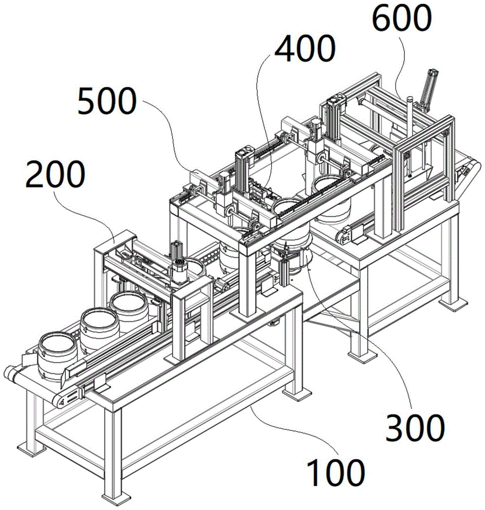
Fig. 1 to 5 show a first embodiment of an apparatus for automatically adjusting and detecting the resistance of an electrofusion pipe fitting according to the present invention.
An automatic adjusting and detecting device for electric smelting pipe fitting resistance comprises an operation table 100, a material distribution mechanism 200 which is connected to the operation table 100 and used for arranging a plurality of electric smelting pipe fittings in a line and conveying the electric smelting pipe fittings one by one, a longitudinal positioning mechanism 300 which is connected to the operation table 100 and used for fixing and rotating the electric smelting pipe fittings, a vertical resistance measuring mechanism 400 which is connected to the operation table 100 and used for matching the longitudinal positioning mechanism 300 to measure the electric smelting pipe fitting resistance, and a gantry feeding mechanism 500 which is connected to the operation table 100 and used for receiving the electric smelting pipe fittings conveyed by the material distribution mechanism 200 and conveying the electric smelting pipe fittings to the longitudinal positioning mechanism 300, wherein the gantry feeding mechanism 500 is arranged at the tail end of the material distribution mechanism 200, and the longitudinal positioning mechanism 300 and the vertical resistance measuring mechanism 400 are arranged at the tail end of the gantry feeding mechanism 500. The electric smelting pipe fittings of any size can be arranged in a line under the action of the material distribution mechanism 200 and are conveyed to the gantry feeding mechanism 500 arranged at the tail end of the material distribution mechanism 200 one by one, the gantry feeding mechanism 500 conveys the electric smelting pipe fittings of any size to the longitudinal positioning mechanism 300 arranged at the tail end of the gantry feeding mechanism 500, the longitudinal positioning mechanism 300 firstly fixes the electric smelting pipe fittings of any size in the axial direction and then rotates the binding posts of the electric smelting pipe fittings to the working surface of the vertical resistance measuring mechanism 400, and the vertical resistance measuring mechanism 400 can measure the resistance of the electric smelting pipe fittings of any size, so that the operation of automatically adjusting the detection resistance of the electric smelting pipe fittings of any size is completed; the automatic resistance detection device solves the technical problem that automatic resistance detection cannot be carried out on electric melting pipe fittings of different sizes in the prior art, is suitable for carrying out automatic resistance detection on electric melting pipe fittings of various sizes, and has the advantages of high automation, high intelligence and high integration and wide application prospect.
Wherein, feed mechanism 200 is including connecting in the first conveyer belt 210 that is used for conveying electric smelting pipe fitting of operation panel 100, the setting is in first conveyer belt 210 traffic direction both sides and be used for contacting and spacing electric smelting pipe fitting's striker plate 220, connect and be used for blockking electric smelting pipe fitting and be equipped with first cylinder 230 of first push rod 231 in striker plate 220, fixed connection is in operation panel 100 and be used for controlling striker plate 220 to draw close and divided first drive arrangement 240, first push rod 231 sets up in the one side that is close to electric smelting pipe fitting, striker plate 220 connects in first drive arrangement 240's output. The first conveyor belt 210 is used for conveying the electrofused pipe fittings, and is matched with the stop plates 220 on the two sides of the conveyor belt to limit the contact of the electrofused pipe fittings, the electrofused pipe fittings are arranged in a straight line in the stop plates 220 on the two sides for conveying, and the first driving device 240 can drive and adjust the distance between the stop plates 220 on the two sides according to the electrofused pipe fittings with different sizes; first cylinder 230 sets up and can follow striker plate 220 on striker plate 220 and adjust together and play the effect of blockking to electric smelting pipe fitting, block when first push rod 231 stretches out that electric smelting pipe fitting on first conveyer belt 210 advances, electric smelting pipe fitting on first conveyer belt 210 continues to advance when first push rod 231 retracts, after an electric smelting pipe fitting passes through first cylinder 230, first push rod 231 stretches out once more and blocks electric smelting pipe fitting thereafter, the conveying one by one of electric smelting pipe fitting has been realized, simple structure convenient to use's advantage has.
The first driving device 240 includes a first fixing frame 241 and a second fixing frame 242 fixed to the operating table 100 and respectively disposed at two sides of the first conveyor belt 210 in the moving direction, a first synchronizing wheel 243 rotatably connected to the first fixing frame 241, a first motor 244 connected to the first fixing frame 241 for driving the first synchronizing wheel 243 to rotate, a second synchronizing wheel 245 rotatably connected to the second fixing frame 242, a first synchronizing belt 246 surrounding outer walls of the first synchronizing wheel 243 and the second synchronizing wheel 245, a first fastening member 247 connected to one side of the first synchronizing belt 246 and close to one side of the first fixing frame 241, a second fastening member 248 connected to the other side of the first synchronizing belt 246 and close to one side of the second fixing frame 242, a first connecting frame 249 connected to the first fastening member 247, and a second connecting frame 250 connected to the second fastening member 248, wherein the first synchronizing wheel 243 is connected to an output shaft of the first motor 244, and the first connecting frame 249 and the second connecting frame 250 are respectively connected to one side of the striker plate 220, which is far away from the pipe. Because the first synchronizing wheel 243 and the second synchronizing wheel 245 are spaced apart from each other, when the first synchronizing belt 246 is driven to rotate, the first synchronizing belt 246 is divided into two average sections moving in opposite directions, because the first fastening member 247 is connected to one side of the first synchronizing belt 246 and close to one side of the first fixing frame 241, and the second fastening member 248 is connected to the other side of the first synchronizing belt 246 and close to one side of the second fixing frame 242, when the first synchronizing belt 246 is driven to rotate clockwise and counterclockwise, the first fastening member 247 and the second fastening member 248 both move in opposite directions, and the first fastening member 247 and the second fastening member 248 respectively drive the first connecting frame 249 and the second connecting frame 250 to simultaneously move closer to and away from each other by controlling the forward and backward rotation of the first synchronizing wheel 243 through the first motor 244, thereby achieving the mutual approaching and leaving of the striker plates 220.
Example two
Fig. 6 to 11 show a second embodiment of the apparatus for automatically adjusting and detecting the resistance of the electrofusion pipe fitting according to the present invention.
The present embodiment is similar to the embodiment, except that: the vertical resistance measuring mechanism 400 comprises a fixed seat 410 connected to the operating platform 100 in a sliding manner, a second driving device 420 used for driving the fixed seat 410 to slide, a testing device 430 provided with a probe 431 used for inserting a binding post, a telescopic device 440 used for controlling the telescopic motion of the testing device 430, a lifting device 450 fixedly connected to the fixed seat 410 and used for controlling the lifting of the telescopic device 440, and a testing baffle 460 fixedly connected to the fixed seat 410 and arranged between the testing device 430 and the longitudinal positioning mechanism 300 and used for abutting against the outer wall of the binding post, wherein the fixed seat 410 is connected to the output end of the second driving device 420, the sliding direction of the fixed seat 410 relative to the operating platform 100 is parallel to the telescopic direction of the testing device 430, the testing device 430 is connected to the output end of the telescopic device 440, the telescopic device 440 is connected to the output end of the lifting device 450, the telescopic direction of the testing device 430 is perpendicular to the lifting direction, and the horizontal distance from the axis of the probe 431 to one side of the testing baffle 460, which is used for abutting against the binding post, is the radius of the binding post. The distance between the vertical resistance measuring mechanism 400 and the electric smelting pipe fitting can be adjusted by controlling the second driving device 420 to drive the fixed seat 410 to slide on the operating platform 100 according to the electric smelting pipe fittings of different sizes, when the longitudinal positioning mechanism 300 fixes the electric smelting pipe fitting and rotates to the contact of the outer wall of the binding post on the test baffle 460, the electric smelting pipe fitting stops rotating under the blocking effect of the test baffle 460 on the binding post, because the horizontal distance from the axis of the probe 431 to one side of the test baffle 460, which is used for abutting against the binding post, is the radius of the binding post, the test device 430 provided with the probe 431 for inserting the binding post can move to the position where the axis of the probe 431 is overlapped with the axis of the binding post under the driving of the lifting device 450, the telescopic device 440 drives the test device 430 to extend, the probe 431 is inserted into the binding post to test the resistance, the telescopic device 440 drives the test device 430 to retract after the test, the resistance detection operation is completed, and the advantage of high automation and intelligence degree is achieved.
The fixed seat 410 is connected with a first sliding block 411, the operating platform 100 is connected with a first sliding rail 412 parallel to the axis of the probe 431, and the first sliding block 411 is connected with the first sliding rail 412 in a sliding manner; the second driving device 420 includes a second motor 421 connected to the fixing base 410, a first gear 422 connected to an output end of the second motor 421, and a first rack 423 disposed parallel to an axis of the probe 431 and connected to the console 100, wherein the first gear 422 is engaged with the first rack 423.
The lifting device 450 includes a third motor 451 fixed to the fixing base 410, a third synchronous wheel 452 connected to an output shaft of the third motor 451, a screw 453 rotatably connected to the fixing base 410, a fourth synchronous wheel 454 connected to an end of the screw 453, a second synchronous belt 455 wrapped around outer walls of the third synchronous wheel 452 and the fourth synchronous wheel 454, a second slide rail 456 fixed to the fixing base 410 and disposed parallel to the screw 453, and a second slide block 457 slidably connected to the second slide rail 456 and threadedly connected to the screw 453, wherein the telescopic device 440 is connected to the second slide block 457. An output shaft of the third motor 451 rotates to drive the third synchronous wheel 452 to rotate to drive the second synchronous belt 455, the second synchronous belt 455 drives the fourth synchronous wheel 454 to rotate, the fourth synchronous wheel 454 rotates to drive the lead screw 453 to rotate, because the second slider 457 is connected to the second slide rail 456 in a sliding manner and is in threaded connection with the lead screw 453, the lead screw 453 rotates to make the second slider 457 slide up and down on the second slide rail 456, because the expansion device 440 is connected to the second slider 457, the independent lifting function of the expansion device 440 can be realized by controlling the sliding of the independent slider through an independent motor.
The telescopic device 440 includes a fourth motor 442 connected to the slider and provided with a fifth push rod 441, a telescopic direction of the fifth push rod 441 is perpendicular to a sliding direction of the second slider 457, and the testing device 430 is connected to an end of the fifth push rod 441. The lifting device 450 cooperates with the fourth motor 442 of the telescoping device 440 to control the extension and retraction of the fifth push rod 441, so that the testing device 430 can freely move in a plane.
The testing device 430 comprises a shaft seat 432 connected to the output end of the telescopic device 440, a limiting sleeve 433 connected to the shaft seat 432 in a sliding mode and used for contacting the outer wall of the binding post, and a spring 434 arranged between the limiting sleeve 433 and the shaft seat 432, wherein the probe 431 is connected to the shaft seat 432 and arranged right below the limiting sleeve 433, a sensor 435 used for contacting the outer wall of the binding post is arranged on one side, close to the probe 431, of the limiting sleeve 433, and the distance from the sensor 435 to the axis of the probe 431 is the radius of the binding post. The sensor 435 arranged on one side of the limiting sleeve 433 close to the probe 431 is used for sensing whether the outer wall of the binding post is contacted or not; because stop collar 433 sets up and just above probe 431 and sliding connection in axle bed 432 again, when probe 431 inserts the terminal the stop collar 433 can support electric smelting pipe fitting outer wall, when probe 431 contracts, and stop collar 433 restores to the normal position under the effect of spring 434, accomplishes the detection resistance action.
The longitudinal positioning mechanism 300 comprises a clamping device 310 which is rotatably connected to the operating platform 100 and used for axially fixing the electrofusion pipe fitting, and a third driving device 320 used for driving the clamping device 310 to rotate, wherein the clamping device 310 is connected to an output end of the third driving device 320, and a rotating shaft of the clamping device 310 coincides with a motion plane where the probe 431 is located and is perpendicular to an axis of the probe 431. Because the rotating shaft of the clamping device 310 coincides with the movement plane where the probe 431 is located and is perpendicular to the axis of the probe 431, after the electric smelting pipe fitting is axially fixed by the clamping device 310, the axis of the terminal can coincide with the movement plane where the probe 431 is located and is parallel to the axis of the probe 431 after the electric smelting pipe fitting is rotated for a certain angle, so that the probe 431 can be inserted into the terminal after performing simple planar movement in the movement plane of the probe 431.
The clamping device 310 comprises a rotating shaft 311 connected to the output end of a third driving device 320, a clamping table 313 axially connected to the rotating shaft 311 and radially and uniformly provided with a plurality of sliding grooves 312, a clamping arm 314 slidably connected to the sliding grooves 312 and used for contacting the inner wall of the electric melting pipe fitting, a roller 315 rotatably connected to one side of the clamping arm 314 away from the electric melting pipe fitting, a wheel groove 316 arranged below the sliding grooves 312 and used for limiting the roller 315 to move up and down, a rotating arm 317 axially connected to one side of the roller 315 away from the clamping arm 314, a partition disc 319 axially rotatably connected to the rotating shaft 311 and radially distributed with a plurality of arc-shaped guide grooves 318 and arranged between the roller 315 and the third driving device 320, and a rotating cylinder 330 used for driving the partition disc 319 to rotate, wherein the roller 315 is slidably connected to the wheel groove 316, the rotating arm is slidably connected to the guide groove 318, one end of the sliding grooves 312 is close to the center of the clamping table 313 and the other end of the sliding grooves 312 is far away from the center of the clamping table 313, one end of the guide groove 318 is close to the center of the partition disc 319 and the other end of the partition disc 319 is connected to the output shaft 319 of the rotating cylinder 330. The rotating shaft 311 drives the electric melting pipe fittings placed on the clamping table 313 to rotate, and the clamping arm 314 plays a role in fixing by applying acting force to the inner walls of the electric melting pipe fittings; because one end of the arc-shaped guide grooves 318 distributed in the radial direction of the split disc 319 is close to the center of the split disc 319 and the other end of the guide grooves 318 is far away from the center of the split disc 319, when the rotary cylinder 330 drives the split disc 319 to rotate, the rotating arm 317 slidably connected in the guide grooves 318 can slide in the guide grooves 318 under the rotating action of the split disc 319, and because the rotating arm 317 is connected to the roller 315 slidably connected in the roller groove 316, the rotating arm 317 radially displaces in the guide grooves 318 to drive the roller 315 to radially slide in the roller groove 316, so as to drive the clamping arm 314 connected with the roller 315 to slide in the sliding groove 312, thereby playing a role of tightening and loosening electric melting pipe fittings.
The third driving unit 320 includes a fifth motor 321 fixed to the operation table 100, and a second gear 322 connected to an output shaft of the fifth motor 321, and the rotating shaft 311 is connected to a third gear 323 engaged with the second gear 322. The fifth motor 321 is used for providing power and transmitting torque in a gear engagement mode.
EXAMPLE III
Fig. 12 to 13 show a third embodiment of the apparatus for automatically adjusting and detecting the resistance of the electrofusion pipe fitting according to the present invention.
This embodiment is similar to the first or second embodiment, except that: the gantry feeding mechanism 500 includes a gantry frame 510 fixed on the operating platform 100, a first feeding arm 520 slidably connected to the gantry frame 510 and disposed between the end of the first conveyor belt 210 and the longitudinal positioning mechanism 300, a fourth driving device 530 connected to the first feeding arm 520 and used for driving the first feeding arm 520 to slide, a second cylinder 540 connected to the first feeding arm 520 and provided with a second push rod 541, and a first clamping jaw cylinder 550 connected to the end of the second push rod 541 and used for grabbing the electric smelting pipe fitting, the first feeding arm 520 is connected to an output shaft of the fourth driving device 530, and the second push rod 541 is disposed at one side close to the electric smelting pipe fitting. The first feeding arm 520 can slide relative to the portal frame 510 between the tail end of the first conveyor belt 210 and the longitudinal positioning mechanism 300 under the driving action of the fourth driving device 530, the second cylinder 540 connected to the first feeding arm 520 enables the first clamping jaw cylinder 550 connected to the end part of the second push rod 541 to be close to the electric smelting pipe fitting at the tail end of the first conveyor belt 210 by extending out the second push rod 541, and the first clamping jaw cylinder 550 can grab the electric smelting pipe fitting by clamping and contacting the outer wall of the electric smelting pipe fitting.
The two sides of the portal frame 510 are provided with third slide rails 511, the first feeding arm 520 is connected with a third slide block 521, and the third slide block 521 is slidably connected with the third slide rails 511; two sides of the portal frame 510 are also provided with second racks 512 parallel to the third sliding rails 511, the first feeding arm 520 is rotatably connected with a first feeding rod 513, and the end part of the first feeding rod 513 is connected with a fourth gear 514 meshed with the second racks 512; the fourth driving means 530 includes a sixth motor 531 connected to the first loading arm 520, a drive bevel gear connected to an output shaft of the sixth motor 531, and a driven bevel gear connected to the first loading arm 513 and engaged with the drive bevel gear, wherein the sixth motor 531 drives the first loading arm 513 to rotate by vertically transmitting torque in a bevel gear engagement manner, thereby driving the fourth gear 514 to roll on the second rack 512.
Example four
Fig. 13 to 14 show a fourth embodiment of the apparatus for automatically adjusting and detecting the resistance of the electrofused pipe according to the present invention.
The present embodiment is similar to any one of the first to third embodiments, except that: the automatic discharging device further comprises a discharging mechanism 600 which is arranged at the tail end of the gantry feeding mechanism 500 and used for discharging unqualified electric melting pipe fittings, the gantry feeding mechanism 500 further comprises a second feeding arm 560 which is connected to the gantry 510 in a sliding mode and arranged between the longitudinal positioning mechanism 300 and the discharging mechanism 600, a fifth driving device 570 which is connected to the second feeding arm 560 and used for driving the second feeding arm 560 to slide, a third air cylinder 580 which is connected to the second feeding arm 560 and provided with a third push rod 581, and a second clamping jaw air cylinder 590 which is connected to the end portion of the third push rod 581 and used for grabbing the electric melting pipe fittings, the second feeding arm 560 is connected to an output shaft of the fifth driving device 570, and the third push rod 581 is arranged on one side close to the electric melting pipe fittings. The removing mechanism 600 is used for receiving the electric melting pipe fittings transmitted by the gantry feeding mechanism 500 and removing unqualified products; the second feeding arm 560 is driven by the fifth driving device 570 to slide between the longitudinal positioning mechanism 300 and the removing mechanism 600 relative to the gantry 510, the third cylinder 580 connected to the second feeding arm 560 extends the third push rod 581 to enable the second clamping jaw cylinder 590 connected to the end of the third push rod 581 to be close to the electrofusion pipe fitting of the longitudinal positioning mechanism 300, and the second clamping jaw cylinder 590 can grasp the electrofusion pipe fitting by clamping and contacting the outer wall of the electrofusion pipe fitting.
The second feeding arm 560 is rotatably connected with a second feeding rod 561, and the end of the second feeding rod 561 is connected with a fifth gear 562 meshed with the second rack 512; the fifth driving device 570 includes a seventh motor 571 connected to the second loading arm 560, a driving bevel gear connected to an output shaft of the seventh motor 571, and a driven bevel gear connected to the first loading rod 513 and engaged with the first bevel gear, wherein the seventh motor 571 drives the second loading rod 561 to rotate by vertically transmitting torque in a manner of engaging with the bevel gear, thereby driving the fifth gear 562 to roll on the second rack 512.
The removing mechanism 600 includes a second conveyor belt 610 connected to the operating table 100 and configured to receive the electrofused pipe fittings conveyed by the second clamping jaw 590, a removing frame 611 disposed above the second conveyor belt 610, a removing plate 620 slidably connected to the removing frame 611 and configured to abut against the electrofused pipe fittings, a sixth driving device 630 connected to the removing plate 620 and configured to drive the removing plate 620 to slide, a fourth cylinder 640 rotatably connected to the removing frame 611 and configured with a fourth push rod 641, and a fitting plate 650 rotatably connected to the removing frame 611 and an end of the fourth push rod 641, wherein a sliding direction of the removing plate 620 relative to the removing frame 611 is perpendicular to a running direction of the second conveyor belt 610, and rotating shafts between the fourth cylinder 640 and the removing frame 611, between the fourth push rod 641 and the fitting plate 650, and between the fitting plate 650 and the removing frame 611 are perpendicular to the running direction of the conveyor belt. The electric melting pipe fittings conveyed by the second clamping jaw cylinder 590 are firstly placed on the second conveying belt 610, qualified electric melting pipe fittings pass through the qualified plate 650, and the sixth driving device 630 drives the discharging plate 620 to slide in a direction perpendicular to the running direction of the second conveying belt 610 relative to the discharging frame 611, so that the unqualified electric melting pipe fittings are pushed by the discharging plate 620 to move in a direction perpendicular to the running direction of the second conveying belt 610; since the rotation axes between the fourth cylinder 640 and the excluding frame 611, the fourth push rod 641 and the qualified plate 650, and the qualified plate 650 and the excluding frame 611 are perpendicular to the running direction of the conveyor belt, when the fourth cylinder 640 controls to retract the fourth push rod 641, the qualified plate 650 is lifted, and the electric melting pipe can pass through smoothly.
In the detailed description of the embodiments, various technical features may be arbitrarily combined, and for the sake of brevity, all possible combinations of the technical features are not described, but should be considered as being within the scope of the present specification as long as there is no contradiction between the combinations of the technical features.
It should be understood that the above-described embodiments of the present invention are merely examples for clearly illustrating the present invention, and are not intended to limit the embodiments of the present invention. Other variations and modifications will be apparent to persons skilled in the art in light of the above description. This need not be, nor should it be exhaustive of all embodiments. Any modification, equivalent replacement, and improvement made within the spirit and principle of the present invention should be included in the protection scope of the claims of the present invention.