CN115166319A - Insert test fixture in fact - Google Patents
Insert test fixture in fact Download PDFInfo
- Publication number
- CN115166319A CN115166319A CN202211092431.6A CN202211092431A CN115166319A CN 115166319 A CN115166319 A CN 115166319A CN 202211092431 A CN202211092431 A CN 202211092431A CN 115166319 A CN115166319 A CN 115166319A
- Authority
- CN
- China
- Prior art keywords
- block
- rotating shaft
- locking
- hole
- push
- Prior art date
- Legal status (The legal status is an assumption and is not a legal conclusion. Google has not performed a legal analysis and makes no representation as to the accuracy of the status listed.)
- Granted
Links
- 238000012360 testing method Methods 0.000 title claims abstract description 89
- 238000003780 insertion Methods 0.000 claims abstract description 64
- 230000037431 insertion Effects 0.000 claims abstract description 61
- 239000000523 sample Substances 0.000 claims abstract description 26
- 238000005096 rolling process Methods 0.000 claims description 2
- 238000000034 method Methods 0.000 description 8
- 238000004891 communication Methods 0.000 description 7
- 230000007246 mechanism Effects 0.000 description 7
- 230000009471 action Effects 0.000 description 6
- 230000008569 process Effects 0.000 description 6
- 230000006835 compression Effects 0.000 description 4
- 238000007906 compression Methods 0.000 description 4
- 238000012986 modification Methods 0.000 description 2
- 230000004048 modification Effects 0.000 description 2
- 230000001174 ascending effect Effects 0.000 description 1
- 230000009286 beneficial effect Effects 0.000 description 1
- 230000005611 electricity Effects 0.000 description 1
- 230000005484 gravity Effects 0.000 description 1
- 230000006872 improvement Effects 0.000 description 1
- 238000002347 injection Methods 0.000 description 1
- 239000007924 injection Substances 0.000 description 1
- 238000009434 installation Methods 0.000 description 1
- 210000001503 joint Anatomy 0.000 description 1
- 230000007774 longterm Effects 0.000 description 1
- 239000000463 material Substances 0.000 description 1
- 238000011056 performance test Methods 0.000 description 1
- 230000002035 prolonged effect Effects 0.000 description 1
- 239000011435 rock Substances 0.000 description 1
- 239000011800 void material Substances 0.000 description 1
Images


Classifications
-
- G—PHYSICS
- G01—MEASURING; TESTING
- G01R—MEASURING ELECTRIC VARIABLES; MEASURING MAGNETIC VARIABLES
- G01R1/00—Details of instruments or arrangements of the types included in groups G01R5/00 - G01R13/00 and G01R31/00
- G01R1/02—General constructional details
- G01R1/06—Measuring leads; Measuring probes
- G01R1/067—Measuring probes
- G01R1/073—Multiple probes
- G01R1/07307—Multiple probes with individual probe elements, e.g. needles, cantilever beams or bump contacts, fixed in relation to each other, e.g. bed of nails fixture or probe card
-
- G—PHYSICS
- G01—MEASURING; TESTING
- G01R—MEASURING ELECTRIC VARIABLES; MEASURING MAGNETIC VARIABLES
- G01R1/00—Details of instruments or arrangements of the types included in groups G01R5/00 - G01R13/00 and G01R31/00
- G01R1/02—General constructional details
- G01R1/04—Housings; Supporting members; Arrangements of terminals
- G01R1/0408—Test fixtures or contact fields; Connectors or connecting adaptors; Test clips; Test sockets
- G01R1/0416—Connectors, terminals
-
- G—PHYSICS
- G01—MEASURING; TESTING
- G01R—MEASURING ELECTRIC VARIABLES; MEASURING MAGNETIC VARIABLES
- G01R1/00—Details of instruments or arrangements of the types included in groups G01R5/00 - G01R13/00 and G01R31/00
- G01R1/02—General constructional details
- G01R1/04—Housings; Supporting members; Arrangements of terminals
- G01R1/0408—Test fixtures or contact fields; Connectors or connecting adaptors; Test clips; Test sockets
- G01R1/0425—Test clips, e.g. for IC's
-
- H—ELECTRICITY
- H04—ELECTRIC COMMUNICATION TECHNIQUE
- H04L—TRANSMISSION OF DIGITAL INFORMATION, e.g. TELEGRAPHIC COMMUNICATION
- H04L43/00—Arrangements for monitoring or testing data switching networks
- H04L43/50—Testing arrangements
Landscapes
- Physics & Mathematics (AREA)
- General Physics & Mathematics (AREA)
- Engineering & Computer Science (AREA)
- Computer Networks & Wireless Communication (AREA)
- Signal Processing (AREA)
- Measuring Leads Or Probes (AREA)
Abstract
The invention belongs to the technical field of jigs, in particular to a real insertion test jig which comprises a test board, a needle plate and a real insertion module, wherein a product to be tested is positioned on the test board and is electrically connected with an interface of the test board through the real insertion module; the needle plate is provided with a probe, and the needle plate moves relative to the measuring plate to make the probe in on-off connection with a product to be measured; an inserting column is arranged on the needle plate and locked on the workbench through a locking module, so that the probe is pressed against a product to be detected; the locking module comprises a rotating shaft, a top block, a clamping block and an auxiliary locking block, wherein the top block and the clamping block are fixed on the rotating shaft, and the auxiliary locking block and the clamping block are arranged oppositely; the top block inclines towards the oblique upper direction, and when the inserted column presses down the top block, the rotating shaft rotates to enable the clamping block and the auxiliary locking block to be matched with each other to clamp the inserted column; the locking module further comprises a locking shaft assembly used for radially positioning the rotating shaft and preventing the rotating shaft from freely rotating, the locking shaft assembly comprises an insertion block, a slot is formed in the rotating shaft, and the insertion block is inserted into the slot. The probe is reliably and electrically connected with a product to be tested, and the testing beat is fast.
Description
Technical Field
The invention belongs to the technical field of test jigs, and particularly relates to a real insertion test jig.
Background
The real insertion test fixture is used for testing the electrical performance and the communication performance of the real insertion port of the circuit board. During testing, a plurality of air cylinders are usually used for pushing the real insertion module to be inserted tightly on the port and for pressing the needle pressing plate down to press the probe on a product to be tested.
For example, utility model discloses a notice number is CN211741338U discloses a BCU-BDU all-in-one test equipment and test system, and test equipment includes industrial control computer, test system and test fixture, the industrial control computer passes through test system and is connected with test fixture, test fixture including the workstation that is used for placing the test product, set up at workstation one end and be used for with test product communication interface connection insert the module, set up at workstation one end and be used for the test panel who is connected with test product test point, insert the module in fact by drive arrangement drive and interface butt joint, the test panel is by the test point connection of upper and lower movable cylinder drive removal and test product down.
In order to reduce the equipment cost, generally, a driving device adopts an air cylinder, after the air cylinder drives a test panel to move downwards, when the air pressure is unstable, the test panel may shake, and because the probes are in point contact with the test points, the shaking of the test panel causes that the probes cannot be continuously and reliably connected with the test points of a product, thereby affecting the accuracy of the test result. In order to solve the problem, if a group of cylinders and a pressing plate are simply added to be matched to press a test panel or a probe, an operation procedure is added, the test beat is prolonged, and the test efficiency is influenced.
Disclosure of Invention
The invention aims to provide a real-insertion test fixture, which aims to solve the problems that when a test board of the real-insertion test fixture is pressed by an air cylinder, a probe cannot be reliably connected with a test point of a product, the test result is influenced, and the test efficiency is low.
The specific scheme of the invention is as follows:
a real insertion test fixture comprises a test board, a needle plate and a real insertion module, wherein a product to be tested is positioned on the test board and is electrically connected with an interface of the test board through the real insertion module;
the needle plate is provided with a probe, and the needle plate moves relative to the measuring plate to make the probe in on-off connection with the product to be measured; an inserting column is arranged on the needle plate, and during testing, the inserting column is locked on the workbench through a locking module, so that the probe compresses the product to be tested;
the locking module comprises a rotating shaft, a top block, a clamping block and an auxiliary locking block, wherein the top block and the clamping block are fixed in the same circumference of the shaft wall of the rotating shaft, and the auxiliary locking block is fixed on the workbench and arranged opposite to the clamping block; the top block inclines towards the upper oblique direction, and when the inserted column presses down the top block, the rotating shaft rotates to enable the clamping block and the auxiliary locking block to be matched with each other to clamp the inserted column;
the locking module further comprises a locking shaft assembly used for positioning the rotating shaft in the radial direction and preventing the rotating shaft from rotating freely, the locking shaft assembly comprises an insertion block, the rotating shaft is provided with a slot matched with the insertion block, and the insertion block is inserted into the slot.
Preferably, the top block is provided with a compression surface tightly attached to the inserted column, and an included angle between the compression surface and the clamping block is not more than 90 degrees.
Preferably, the top end of the ejector block is provided with a ball groove, a ball is installed in the ball groove, the ball partially protrudes out of the ball groove, and rolling friction is formed between the ball and the bottom surface of the inserted column.
Furthermore, the lock shaft assembly further comprises a socket and an elastic piece, the socket is fixed on the workbench, a sliding cavity for the insertion block to move up and down is formed in the socket, the insertion block and the elastic piece are located in the sliding cavity, and the upper end and the lower end of the elastic piece are respectively abutted against the socket and the insertion block, so that the insertion block is inserted into the insertion slot.
Preferably, a horizontal hole I is arranged in the insertion block; a push-pull electromagnet is arranged on the workbench, a push rod of the push-pull electromagnet is fixed with a push block, and the upper side of the front end of the push block is a wedge-shaped surface;
when the rotating shaft is locked by the locking shaft assembly, the push block is separated from the first hole, and the height of at least one part of the wedge-shaped surface is higher than that of the first hole;
when the rotating shaft needs to be unlocked, the push-pull type electromagnet pushes the push block out, the wedge-shaped surface is inserted into the first hole and jacks up the insertion block, and the insertion block is separated from the slot.
Preferably, the top of the socket is provided with a second hole vertically communicated with the sliding cavity, the top of the insertion block is fixedly provided with a guide rod matched with the second hole, and the guide rod slides up and down along the second hole.
Furthermore, a first pressing block is fixed on the rotating shaft, and a second pressing block is fixed on the workbench;
and the rotating shaft is further sleeved with a torsional spring, the torsional spring comprises a first force application end and a second force application end, the first force application end is abutted against the first pressing block, and the second force application end is abutted against the upper part of the second pressing block.
Preferably, when the rotating shaft is locked, the pressing block is positioned at the top of the rotating shaft;
the first force application end is connected with two groups of spring coils, and each group of spring coils is provided with a second force application end;
the first force application end is of an inverted U shape, and the first force application end is obliquely sleeved on the first pressing block; during testing, the first force application end extrudes the first pressing block to enable the rotating shaft to have a resetting trend.
Preferably, the bottom of the auxiliary locking block is provided with a clearance groove, and the top block passes through the clearance groove when rotating along with the rotating shaft.
Preferably, the workbench is provided with a strip-shaped shaft hole, the rotating shaft is positioned in the shaft hole, and two ends of the rotating shaft are supported by bearings in the shaft hole; two groups of locking modules are arranged on the left side and the right side of the rotating shaft and used for locking two inserting columns on the needle plate; and the two inserting columns are fixedly connected by a handle and used for lifting the needle plate when the needle plate is turned over.
The beneficial effects of the invention are:
before testing, the pin plate is opened or lifted, so that the probe is not in electric contact with a product to be tested. During testing, the needle plate is pressed down, and the inserted columns on the needle plate are locked on the workbench through the locking module, so that the probe reliably compresses a product to be tested, and the electrical performance test is completed. The locking module is characterized in that a rotating shaft, a top block, a clamping block and an auxiliary locking block are matched with each other, the inclined top block is extruded by the aid of gravity of a needle plate and an insertion column, the rotating shaft is automatically pushed to rotate, the clamping block on the rotating shaft is matched with the auxiliary locking block to automatically clamp the insertion column, the insertion column is prevented from shaking, stable electrical connection between a probe and a test point of a product to be tested is realized, and the phenomenon that the needle plate shakes due to unstable air pressure of an air cylinder is avoided; and an external driving device is not required to be added in the locking process of the inserted column, and meanwhile, as the falling of the needle plate and the locking action are synchronously carried out, the driving device is not required to be started to act to press the needle plate after the inserted column falls, so that the working procedure beat is shortened, and the testing efficiency is improved.
The lock shaft assembly further locks the rotating shaft, and the phenomenon that the clamping block clamps the inserted column unstably due to slight rotation of the rotating shaft is avoided. When the inserting column is clamped by the clamping block, the inserting block of the locking shaft assembly is automatically inserted into the slot on the rotating shaft to radially position the rotating shaft.
The elastic part and the plug block of the lock shaft assembly are both located in the sliding cavity of the socket, and the elastic part extrudes the plug block into the slot to realize automatic locking of the shaft. The plug-in block is internally provided with a horizontal hole I, a push block with a wedge-shaped surface is arranged on a push rod of the push-pull electromagnet, and one part of the wedge-shaped surface is higher than the hole I, so that when the rotating shaft needs to be unlocked, the push-pull electromagnet extends out of the push block, the wedge-shaped surface is inserted into the hole I and jacks up the plug block, the plug block is automatically separated from the slot, and the rotating shaft can rotate freely at the moment. The push-pull electromagnet is quick in action, the stretching action is about 0.10 second, the returning action is about 0.05 second or less, the operation frequency is 3800 times/hour or more, the push-pull electromagnet can be frequently started to work, and the push-pull electromagnet can be electrified and attracted for a long time.
Drawings
The accompanying drawings, which are included to provide a further understanding of the invention and are incorporated in and constitute a part of this specification, illustrate embodiments of the invention and together with the description serve to explain the principles of the invention and not to limit the invention. In the drawings:
fig. 1 is a schematic perspective view of embodiment 1 of the present invention;
fig. 2 is a schematic front view of embodiment 2 of the present invention;
FIG. 3 is a schematic top view of the structure of embodiment 2 of the present invention;
FIG. 4 is a schematic cross-sectional view of a top block and a clamping block on a rotating shaft in an initial state according to embodiment 2 of the present invention;
FIG. 5 is an enlarged view of the portion A in FIG. 4;
fig. 6 is a schematic sectional view showing the insert post clamped by the clamping block according to embodiment 2 of the present invention;
FIG. 7 is a cross-sectional view showing the lock shaft assembly of embodiment 3 of the present invention locking a rotary shaft;
FIG. 8 is a schematic cross-sectional view of portion B-B of FIG. 7 in accordance with the present invention;
FIG. 9 is a schematic sectional view showing the lock shaft assembly of embodiment 3 of the present invention unlocking the rotational shaft;
FIG. 10 is a schematic cross-sectional view of portion C-C of FIG. 9 of the present invention;
fig. 11 is a schematic structural view of a return mechanism according to embodiment 4 of the present invention;
fig. 12 is an enlarged structural view of a reset mechanism of a portion D in fig. 3;
FIG. 13 is a schematic cross-sectional view of the return mechanism on the rotary shaft when the plug post of embodiment 4 of the present invention is locked;
fig. 14 is a schematic cross-sectional view of the reset mechanism on the rotating shaft when the plug post of embodiment 4 of the invention is unlocked.
The reference signs are: 1. a work table; 2. measuring a plate; 3. a cylinder; 4. a real insertion module; 5. a positioning column; 6. a needle plate; 7. a probe; 8. inserting a column; 9. a handle; 10. a hook; 11. buckling; 12. a rotating shaft; 13. a top block; 14. a clamping block; 15. an auxiliary locking block; 16. a shaft hole; 17. a pressure receiving surface; 18. a ball groove; 19. a ball bearing; 20. avoiding a void groove; 21. a lock shaft assembly; 22. inserting a block; 23. a socket; 24. an elastic member; 25. a slide chamber; 26. inserting slots; 27. a first hole; 28. a push-pull electromagnet; 29. a push block; 30. a wedge-shaped surface; 31. a second hole; 32. a guide bar; 33. a reset mechanism; 34. pressing a first block; 35. pressing a second block; 36. a torsion spring; 37. a first force application end; 38. a second force application end; 39. and a spring coil.
Detailed Description
Example 1
The embodiment provides a real-insertion test fixture for testing electrical performance and communication performance of a product to be tested.
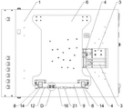
Referring to fig. 1, the present embodiment includes a workbench 1, and a program-controlled computer, a power supply, and a touch screen are installed on the workbench 1. The program-controlled computer is used for controlling the starting of the detection program, collecting the test signal and operating the internal detection program; the power supply provides required test voltage for the product to be tested.
The horizontal measuring plate 2 is arranged on the workbench 1, and a plurality of interfaces are arranged on the measuring plate 2. A plurality of air cylinders 3 are further installed in the workbench 1, the air cylinders 3 drive the real insertion module 4 to move horizontally, so that the real insertion module is electrically connected or in communication connection with corresponding interfaces, and tests such as resistance, voltage and communication signals of a product to be tested are completed according to programs in the program-controlled computer. The real insertion module 4 stores the test result in the program control computer and displays the test result through the touch screen. The plug-in module 4 is a known product.
The measuring plate 2 is provided with a plurality of positioning columns 5, the product to be measured is provided with a plurality of positioning holes, and the positioning columns 5 are matched with the positioning holes to position the product to be measured on the measuring plate 2.
Install faller 6 on the workstation 1, a plurality of probes 7 of bottom surface installation of faller 6 remove faller 6 to the direction of survey board 2 during the test, make probe 7 and the product electricity that awaits measuring be connected for carry out the heavy current injection test to the product that awaits measuring. The mounting means of faller can reciprocate by the cylinder drive, perhaps overturns the action through pneumatics or manual mode, and in this embodiment, faller 6 articulates on workstation 1, opens faller 6 earlier during the test, and the product that will await measuring is conveniently placed fast on surveying board 2, then overturns faller 6, makes probe 7 press on the product that awaits measuring.
Two inserting columns 8 are arranged on the needle plate 6, the two inserting columns 8 are fixedly connected through a handle 9, and the needle plate 6 can be lifted by using the handle 9 when the needle plate 6 is overturned.
The bottom of inserting the post 8 is equipped with pothook 10, installs on the workstation 1 with pothook 10 complex buckle 11, during the test, presses down the faller 6, makes pothook 10 slightly warp when buckle 11, until hooking buckle 11, makes inserting post 8 and workstation 1 fixed connection to compress tightly probe 7 on the product that awaits measuring.
Example 2
Since the hook 10 of embodiment 1 is locked with the buckle 11 by the limited deformation of its material itself, the hook 10 may be deformed and hard to recover after long-term use, so that the needle plate still becomes loose, resulting in the probe 7 not being able to reliably press the product to be tested.
As shown in fig. 2 to 6, the present embodiment is different from embodiment 1 in that the locking structure of the plug post 8 is changed, the hook 10 is not provided at the bottom of the plug post 8, and the buckle 11 is not provided on the workbench 1. During the test, insert post 8 and lock on workstation 1 by the locking module, make probe 7 compress tightly the product that awaits measuring reliably, accomplish the heavy current and pour into the test into, because insert post 8 is locked, consequently faller 6 can not rock, can not take place virtual connecing and lead to contact resistance steep increase phenomenon between probe 7 and the product that awaits measuring.
Referring to fig. 4 to 6, the locking module includes a rotating shaft 12, a top block 13, a clamping block 14 and an auxiliary locking block 15, a long-strip-shaped shaft hole 16 is formed in the workbench 1, bearings are mounted at two ends of the shaft hole, two ends of the rotating shaft 12 are mounted in the shaft hole 16 through the bearings, the top block 13 and the clamping block 14 are arranged on the left side and the right side of the rotating shaft 12 and used for simultaneously locking the left inserting column 8 and the right inserting column 8, and the top block 13 and the clamping block 14 are welded and fixed in the same circumference on the shaft wall of the rotating shaft 12. The auxiliary locking piece 15 is welded or screwed on the workbench 1 and is arranged opposite to the clamping piece 14 when the rotating shaft 12 is locked.
The cross section of the top block 13 is similar to a triangle, the top block is provided with a smooth pressure receiving surface 17, the top of the pressure receiving surface 17 inclines towards one side of the auxiliary locking block 15, when the inserted column 8 is pressed on the top block 13, the top block 13 is extruded towards one side of the auxiliary locking block 15, the rotating shaft 12 rotates clockwise, the rotation is stopped until the pressure receiving surface 17 clings to the inserted column 8, and at the moment, the clamping block 14 just rotates to abut against the inserted column 8, so that the inserted column 8 is clamped and clamped by matching with the auxiliary locking block 15. The angle a between the pressure receiving surface 17 and the clamping block 14 is not more than 90 °, preferably 85-90 °, so that the clamping block 14 can reliably clamp the plug 8.
Referring to fig. 5, a ball groove 18 is formed at the top end of the top block 13, a ball 19 is installed in the ball groove 18, the top of the ball 19 slightly protrudes out of the top block 13, and when the plug 8 downwardly presses the top block 13, the ball 19 and the bottom surface of the plug 8 roll and rub, so that the plug 8 and the top block 13 are prevented from being worn due to excessive friction between the plug 8 and the top block 13.
Referring to fig. 6, a clearance groove 20 is formed at the bottom of the auxiliary locking piece 15, and when the top piece 13 rotates along with the rotating shaft 12, the top piece does not interfere with the auxiliary locking piece 15 through the clearance groove 20.
The other structure of this embodiment is the same as embodiment 1.
Example 3
As shown in fig. 7 to 10, this embodiment further provides a shaft locking assembly 21 on the basis of embodiment 2, for radially positioning the rotating shaft 12, so as to prevent the rotating shaft 12 from slightly rotating back and forth due to vibration during the test, which results in that the plug 8 cannot be locked continuously, thereby ensuring that the test process is performed reliably.
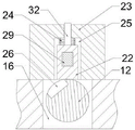
The lock shaft assembly 21 comprises an insertion block 22, a socket 23 and an elastic piece 24, the socket 23 is fixed on the workbench 1, a sliding cavity 25 for the insertion block 22 to move up and down is arranged in the socket 23, and the insertion block 22 and the elastic piece 24 are both located in the sliding cavity 25. The rotating shaft 12 is provided with a slot 26 matched with the plug block 22, and the upper end and the lower end of the elastic piece 24 are respectively abutted against the socket 23 and the plug block 22, so that the plug block 22 is plugged in the slot 26, and the rotating shaft 12 is radially positioned and prevented from freely rotating. The resilient member 24 is preferably a compression spring.
A first horizontal hole 27 is provided in the insert block 22. A push-pull electromagnet 28 is arranged on the workbench 1, a push rod of the push-pull electromagnet 28 is fixed with a push block 29, and the upper side of the front end of the push block 29 is a wedge-shaped surface 30. The push-pull electromagnet 28 is powered by a power source.
Referring to fig. 7 and 8, when the shaft 12 is locked by the shaft locking assembly 21, the insertion block 22 is pressed into the insertion slot 26 by the elastic member 24, the pushing block 29 is separated from the first hole 27, and at least a portion of the height of the wedge surface 30 is higher than the height of the first hole 27;
referring to fig. 9 and 10, when the spindle 12 needs to be unlocked, the push-pull electromagnet 28 is energized to push the push block 29 forward, the wedge surface 30 thereof is inserted into the first hole 27, and the plug block 22 is jacked up by using the height difference between the wedge surface 30 and the first hole 27, so that the plug block 22 is separated from the slot 26, and the spindle 12 can rotate freely.
In the process of jacking the first hole 27 by the wedge-shaped surface 30, in order to enable the plug block 22 to stably rise, a second hole 31 which is vertically communicated with the sliding cavity 25 is formed in the top of the socket 23, a guide rod 32 which is matched with the second hole 31 is welded to the top of the plug block 22, and in the unlocking process, the guide rod 32 slides up and down along the second hole 31, so that the plug block 22 is always kept in a vertical state in the ascending process and cannot deflect.
The other structure of this embodiment is the same as embodiment 2.
Example 4
In this embodiment, a reset mechanism 33 is further provided on the basis of embodiment 3, so that the rotating shaft 12 automatically rotates in the reverse direction to an initial state to wait for the next test.
The specific structure of the return mechanism 33 is as follows:
as shown in fig. 11 to 14, the first pressing block 34 is fixed on the rotating shaft 12, and the second pressing block 35 is fixed on the working table 1. The rotating shaft 12 is further sleeved with a torsion spring 36, and the torsion spring 36 includes a first force application end 37, two sets of coils 39 and a second force application end 38. The first force application end 37 is in an inverted U shape, the first force application end 37 is connected with two groups of spring coils 39, each group of spring coils 39 is provided with a second force application end 38, and the second force application ends 38 are always abutted to the upper side of the second pressing block 35. The first force application end 37 is obliquely sleeved on the first pressing block 34, and during testing, the first force application end 37 outwards presses the first pressing block 34, so that the rotating shaft 12 has a resetting trend of reverse rotation.
Referring to fig. 12 and 13, when the shaft 12 is locked, the first pressing piece 34 is located at the top of the shaft 12. Referring to fig. 14, when the rotating shaft 12 is unlocked, the torsion spring 36 releases the pressure, and the first force applying end 37 pulls the first pressing block 34 outward to drive the rotating shaft 12 to rotate reversely until the first pressing block 34 is limited by the shaft hole 16 and cannot rotate continuously, so that the rotating shaft 12 automatically resets.
The other structure of this embodiment is the same as embodiment 3.
The working process of the embodiment is as follows:
opening the needle plate 6, placing a product to be detected on the measuring plate 2, and accurately positioning by the positioning hole;
covering the needle plate 6, enabling the inserted column 8 to downwards extrude the ejector block 13, enabling the ejector block 13 to rotate towards one side of the auxiliary locking block 15, driving the rotating shaft 12 to rotate clockwise, and enabling the rotating shaft 12 not to rotate continuously until the compression surface 17 of the ejector block 13 is tightly attached to the inserted column 8, and enabling the clamping block 14 to be automatically abutted against the inserted column 8 and to be matched with the auxiliary locking block 15 to clamp the inserted column 8;
before the rotating shaft 12 rotates, the push block 29 of the lock shaft assembly 21 is pushed out by the push-pull electromagnet 28, and the wedge surface 30 of the push block jacks up the insert block 22, so that the rotating shaft 12 can rotate freely; during testing, the slot 26 on the rotating shaft 12 just rotates to the position right below the insert block 22, then the push-pull type electromagnet 28 is controlled to strain the push block 29, the push block 29 slides out of the first hole 27 to release the insert block 22, and the insert block 22 is extruded into the slot 26 by the elastic piece 24, so that the rotating shaft 12 is radially positioned, free rotation of the rotating shaft is prevented, and the insert block 14 is reliably locked to the insert column 8;
the air cylinder 3 drives the real insertion module 4 to move towards the product to be tested until the real insertion module is electrically connected or in communication connection with the interface on the test board 2, and sends current, voltage and communication signals to the program-controlled computer; after the program-controlled computer finishes testing according to the set program, sending the test result to the touch screen for displaying;
the push-pull electromagnet 28 of the lock shaft assembly 21 pushes out the push block 29 again to unlock the rotating shaft 12; the rotating shaft 12 automatically rotates reversely under the pressure of the first force application end 37 of the torsion spring 36, so that the clamping block 14 is reset to the initial angle, and the inserting column 8 is automatically unlocked;
the cylinder 3 withdraws the real insertion module 4, opens the needle plate 6 and takes away the product to be tested;
and repeating the above actions to finish the test of other products.
Although the present invention has been described in detail with reference to the foregoing embodiments, it will be apparent to those skilled in the art that modifications may be made to the embodiments described above, or equivalents may be substituted for elements thereof. Any modification, equivalent replacement, or improvement made within the spirit and principle of the present invention should be included in the protection scope of the present invention.
Claims (10)
1. The utility model provides a real test fixture of inserting, includes survey board, faller and real module of inserting, its characterized in that:
the product to be tested is positioned on the testing plate and is electrically connected with the interface of the testing plate through the real insertion module;
the needle plate is provided with a probe, and the needle plate moves relative to the measuring plate to make the probe in on-off connection with the product to be measured; an inserting column is arranged on the needle plate, and during testing, the inserting column is locked on the workbench through a locking module, so that the probe tightly presses the product to be tested;
the locking module comprises a rotating shaft, a top block, a clamping block and an auxiliary locking block, wherein the top block and the clamping block are fixed in the same circumference of the shaft wall of the rotating shaft, and the auxiliary locking block is fixed on the workbench and arranged opposite to the clamping block; the top of the top block inclines towards one side of the auxiliary locking block, and when the inserted column presses down the top block, the rotating shaft rotates to enable the clamping block and the auxiliary locking block to be matched with each other to clamp the inserted column;
the locking module further comprises a locking shaft assembly, the locking shaft assembly is used for positioning the rotating shaft in the radial direction and preventing the rotating shaft from rotating freely, the locking shaft assembly comprises an insertion block, the rotating shaft is provided with a slot matched with the insertion block, and the insertion block is inserted into the slot.
2. The practical insertion test fixture according to claim 1, wherein the top block is provided with a pressed surface clinging to the insertion column, and an included angle between the pressed surface and the clamping block is not more than 90 °.
3. The practical insertion test fixture according to claim 1, wherein a ball groove is formed at a top end of the top block, a ball is mounted in the ball groove, the ball partially protrudes out of the ball groove, and the ball and the bottom surface of the insertion column are in rolling friction.
4. The practical insertion test fixture according to any one of claims 1 to 3, wherein the lock shaft assembly further comprises a socket and an elastic member, the socket is fixed on the workbench, a sliding cavity for the insertion block to move up and down is arranged in the socket, the insertion block and the elastic member are both located in the sliding cavity, and the upper end and the lower end of the elastic member are respectively abutted against the socket and the insertion block, so that the insertion block is inserted into the insertion slot.
5. The practical insertion test fixture according to claim 4, wherein a first horizontal hole is formed in the insertion block; a push-pull electromagnet is arranged on the workbench, a push rod of the push-pull electromagnet is fixed with a push block, and the upper side of the front end of the push block is a wedge-shaped surface;
when the rotating shaft is locked by the locking shaft assembly, the push block is separated from the first hole, and the height of at least one part of the wedge-shaped surface is higher than that of the first hole;
when the rotating shaft needs to be unlocked, the push-pull type electromagnet pushes the push block out, the wedge-shaped surface is inserted into the first hole and jacks up the insert block, and the insert block is separated from the slot.
6. The practical insertion test fixture according to claim 5, wherein a second hole vertically communicating with the sliding cavity is formed in the top of the socket, a guide rod adapted to the second hole is fixed to the top of the insertion block, and the guide rod slides up and down along the second hole.
7. The practical insertion test fixture according to any one of claims 1 to 3,
a first pressing block is fixed on the rotating shaft, and a second pressing block is fixed on the workbench;
and the rotating shaft is further sleeved with a torsional spring, the torsional spring comprises a first force application end and a second force application end, the first force application end is abutted against the first pressing block, and the second force application end is abutted against the upper part of the second pressing block.
8. The practical insertion test fixture according to claim 7,
the first force application end is connected with two groups of spring coils, and each group of spring coils is provided with a second force application end;
the first force application end is in an inverted U shape and is obliquely sleeved on the first pressing block;
during testing, the rotating shaft is locked, the first pressing block is located at the top of the rotating shaft, and the first force application end extrudes the first pressing block, so that the rotating shaft has a resetting trend.
9. The practical insertion test fixture according to any one of claims 1 to 3, wherein a clearance groove is formed at the bottom of the auxiliary lock block, and the top block passes through the clearance groove when rotating along with the rotating shaft.
10. The practical insertion test fixture according to any one of claims 1 to 3, wherein the workbench is provided with an elongated shaft hole, the rotating shaft is located in the shaft hole, and two ends of the rotating shaft are supported by bearings in the shaft hole; two sets of locking modules are installed on the left side and the right side of the rotating shaft and used for locking the two inserting columns on the needle plate.
Priority Applications (1)
| Application Number | Priority Date | Filing Date | Title |
|---|---|---|---|
| CN202211092431.6A CN115166319B (en) | 2022-09-08 | 2022-09-08 | Real test fixture of inserting |
Applications Claiming Priority (1)
| Application Number | Priority Date | Filing Date | Title |
|---|---|---|---|
| CN202211092431.6A CN115166319B (en) | 2022-09-08 | 2022-09-08 | Real test fixture of inserting |
Publications (2)
| Publication Number | Publication Date |
|---|---|
| CN115166319A true CN115166319A (en) | 2022-10-11 |
| CN115166319B CN115166319B (en) | 2022-12-02 |
Family
ID=83480739
Family Applications (1)
| Application Number | Title | Priority Date | Filing Date |
|---|---|---|---|
| CN202211092431.6A Active CN115166319B (en) | 2022-09-08 | 2022-09-08 | Real test fixture of inserting |
Country Status (1)
| Country | Link |
|---|---|
| CN (1) | CN115166319B (en) |
Citations (12)
| Publication number | Priority date | Publication date | Assignee | Title |
|---|---|---|---|---|
| EP0822417A2 (en) * | 1996-08-01 | 1998-02-04 | AXIS S.p.A. | Probe positioning assembly for armature tester |
| CN2898837Y (en) * | 2006-01-06 | 2007-05-09 | 中兴通讯股份有限公司 | Interface device of testing clamp |
| WO2007057990A1 (en) * | 2005-11-15 | 2007-05-24 | Advantest Corporation | Electronic component test equipment and method for loading performance board on the electronic component test equipment |
| CN209878944U (en) * | 2019-01-16 | 2019-12-31 | 昆山明创电子科技有限公司 | FCT and ICT two-in-one test fixture for real insertion test |
| CN211741338U (en) * | 2019-10-30 | 2020-10-23 | 安徽贵博新能科技有限公司 | BCU-BDU all-in-one test equipment and test system |
| CN212334103U (en) * | 2020-05-09 | 2021-01-12 | 绍兴兴明染整有限公司 | Cloth rolling device convenient to loading and unloading |
| CN212693957U (en) * | 2020-06-22 | 2021-03-12 | 昆山嘉海龙电子有限公司 | Circuit board overvoltage test fixture |
| CN215180673U (en) * | 2021-04-20 | 2021-12-14 | 上海明波通信技术股份有限公司 | Double-channel PCBA test platform |
| CN215575287U (en) * | 2021-09-18 | 2022-01-18 | 深圳市浦洛电子科技有限公司 | Accurate needle bed tool counterpoints |
| CN215932073U (en) * | 2021-01-20 | 2022-03-01 | 汕头职业技术学院 | Intelligent closestool control circuit board testing arrangement |
| CN114411323A (en) * | 2021-12-24 | 2022-04-29 | 石狮市成鑫针织机械有限公司 | Circular knitting machine with adjustable pressing plate |
| CN216526164U (en) * | 2021-12-07 | 2022-05-13 | 深圳市视景达科技有限公司 | Function testing device for liquid crystal television PCBA board |
-
2022
- 2022-09-08 CN CN202211092431.6A patent/CN115166319B/en active Active
Patent Citations (12)
| Publication number | Priority date | Publication date | Assignee | Title |
|---|---|---|---|---|
| EP0822417A2 (en) * | 1996-08-01 | 1998-02-04 | AXIS S.p.A. | Probe positioning assembly for armature tester |
| WO2007057990A1 (en) * | 2005-11-15 | 2007-05-24 | Advantest Corporation | Electronic component test equipment and method for loading performance board on the electronic component test equipment |
| CN2898837Y (en) * | 2006-01-06 | 2007-05-09 | 中兴通讯股份有限公司 | Interface device of testing clamp |
| CN209878944U (en) * | 2019-01-16 | 2019-12-31 | 昆山明创电子科技有限公司 | FCT and ICT two-in-one test fixture for real insertion test |
| CN211741338U (en) * | 2019-10-30 | 2020-10-23 | 安徽贵博新能科技有限公司 | BCU-BDU all-in-one test equipment and test system |
| CN212334103U (en) * | 2020-05-09 | 2021-01-12 | 绍兴兴明染整有限公司 | Cloth rolling device convenient to loading and unloading |
| CN212693957U (en) * | 2020-06-22 | 2021-03-12 | 昆山嘉海龙电子有限公司 | Circuit board overvoltage test fixture |
| CN215932073U (en) * | 2021-01-20 | 2022-03-01 | 汕头职业技术学院 | Intelligent closestool control circuit board testing arrangement |
| CN215180673U (en) * | 2021-04-20 | 2021-12-14 | 上海明波通信技术股份有限公司 | Double-channel PCBA test platform |
| CN215575287U (en) * | 2021-09-18 | 2022-01-18 | 深圳市浦洛电子科技有限公司 | Accurate needle bed tool counterpoints |
| CN216526164U (en) * | 2021-12-07 | 2022-05-13 | 深圳市视景达科技有限公司 | Function testing device for liquid crystal television PCBA board |
| CN114411323A (en) * | 2021-12-24 | 2022-04-29 | 石狮市成鑫针织机械有限公司 | Circular knitting machine with adjustable pressing plate |
Non-Patent Citations (2)
| Title |
|---|
| 宋巧莲等: "新型模块化结构的ICT测试治具设计", 《工具技术》 * |
| 顾吉等: "一种微型探针台的设计和应用", 《电子与封装》 * |
Also Published As
| Publication number | Publication date |
|---|---|
| CN115166319B (en) | 2022-12-02 |
Similar Documents
| Publication | Publication Date | Title |
|---|---|---|
| CN216816869U (en) | Test fixture for detecting PCB and display function thereof | |
| CN108226686A (en) | Mobile phone charger test equipment | |
| CN115166319B (en) | Real test fixture of inserting | |
| CN111879978A (en) | Test fixture and test device | |
| CN222866209U (en) | Automatic press detection device for computer keyboard | |
| CN207992345U (en) | Mobile phone charger test equipment | |
| CN117526615B (en) | Wet friction braking high-torque permanent magnet motor | |
| CN207992346U (en) | Mobile phone charger testing device | |
| CN112461531A (en) | Reliability test device for elastic chuck of numerical control machine tool | |
| CN118150996A (en) | Life testing device for ajar and push button | |
| CN217133223U (en) | Universal measuring clamp | |
| CN213023451U (en) | BMS module circuit board detection device and its test fixture | |
| CN214013670U (en) | Positioning mechanism for drawer on low-voltage electric appliance cabinet | |
| CN212060485U (en) | Positioner of fisheye camera lens PCB board | |
| CN115656566A (en) | Discharge socket detection positioning device | |
| CN112421464A (en) | A positioning mechanism for a drawer on a low-voltage electrical cabinet | |
| CN222979745U (en) | Battery testing device | |
| CN223611562U (en) | A needle plate adjustment mechanism on a needle bed base | |
| CN222379739U (en) | Clamping mechanism for pressure-resistant detection device of radio frequency coaxial connector | |
| CN219456286U (en) | Three-phase copper bar quick butt joint module | |
| CN216116695U (en) | Spring fatigue testing machine | |
| CN221378201U (en) | Battery current testing machine | |
| CN218674206U (en) | Wire spring jack insertion resistance detection device | |
| CN219533244U (en) | Double-station circuit board detection tool | |
| CN118091383B (en) | Fingerprint lock circuit board function test subassembly |
Legal Events
| Date | Code | Title | Description |
|---|---|---|---|
| PB01 | Publication | ||
| PB01 | Publication | ||
| SE01 | Entry into force of request for substantive examination | ||
| SE01 | Entry into force of request for substantive examination | ||
| GR01 | Patent grant | ||
| GR01 | Patent grant |