CN115159643B - A disinfection powder is thrown and is added equipment for sewage treatment - Google Patents
A disinfection powder is thrown and is added equipment for sewage treatment Download PDFInfo
- Publication number
- CN115159643B CN115159643B CN202211095488.1A CN202211095488A CN115159643B CN 115159643 B CN115159643 B CN 115159643B CN 202211095488 A CN202211095488 A CN 202211095488A CN 115159643 B CN115159643 B CN 115159643B
- Authority
- CN
- China
- Prior art keywords
- wall
- tank body
- spiral conveying
- fixed mounting
- sewage treatment
- Prior art date
- Legal status (The legal status is an assumption and is not a legal conclusion. Google has not performed a legal analysis and makes no representation as to the accuracy of the status listed.)
- Active
Links
Images


Classifications
-
- C—CHEMISTRY; METALLURGY
- C02—TREATMENT OF WATER, WASTE WATER, SEWAGE, OR SLUDGE
- C02F—TREATMENT OF WATER, WASTE WATER, SEWAGE, OR SLUDGE
- C02F1/00—Treatment of water, waste water, or sewage
- C02F1/50—Treatment of water, waste water, or sewage by addition or application of a germicide or by oligodynamic treatment
-
- B—PERFORMING OPERATIONS; TRANSPORTING
- B01—PHYSICAL OR CHEMICAL PROCESSES OR APPARATUS IN GENERAL
- B01F—MIXING, e.g. DISSOLVING, EMULSIFYING OR DISPERSING
- B01F27/00—Mixers with rotary stirring devices in fixed receptacles; Kneaders
- B01F27/55—Mixers with rotary stirring devices in fixed receptacles; Kneaders with stirrers driven by the moving material
-
- B—PERFORMING OPERATIONS; TRANSPORTING
- B01—PHYSICAL OR CHEMICAL PROCESSES OR APPARATUS IN GENERAL
- B01F—MIXING, e.g. DISSOLVING, EMULSIFYING OR DISPERSING
- B01F35/00—Accessories for mixers; Auxiliary operations or auxiliary devices; Parts or details of general application
- B01F35/10—Maintenance of mixers
- B01F35/12—Maintenance of mixers using mechanical means
-
- B—PERFORMING OPERATIONS; TRANSPORTING
- B01—PHYSICAL OR CHEMICAL PROCESSES OR APPARATUS IN GENERAL
- B01F—MIXING, e.g. DISSOLVING, EMULSIFYING OR DISPERSING
- B01F35/00—Accessories for mixers; Auxiliary operations or auxiliary devices; Parts or details of general application
- B01F35/71—Feed mechanisms
-
- C—CHEMISTRY; METALLURGY
- C02—TREATMENT OF WATER, WASTE WATER, SEWAGE, OR SLUDGE
- C02F—TREATMENT OF WATER, WASTE WATER, SEWAGE, OR SLUDGE
- C02F2303/00—Specific treatment goals
- C02F2303/04—Disinfection
Abstract
The invention relates to the technical field of sewage treatment, in particular to disinfection powder feeding equipment for sewage treatment, which comprises a tank body, a tank cover hinged at the top end of the tank body, a water inlet pipe and a water outlet pipe fixedly arranged on the side wall of the tank body, and a feeding port fixedly arranged at the upper end of the tank cover, wherein a collecting groove is fixedly arranged on the inner wall of the tank body, a driving rod is rotatably arranged between the bottom wall of the tank body and the bottom of the collecting groove, and two second spiral conveying blades which are symmetrically arranged are rotatably arranged on the inner wall of the collecting groove. According to the invention, through arranging the first spiral conveying blade, the second spiral conveying blade, the adding pipe and other mechanisms, an operator inputs sewage into the tank body from the water inlet pipe, and adds the disinfection powder from the material inlet, the sewage drives the driving assembly to generate power when flowing in the tank body, the driving assembly drives the driving rod to rotate, the driving rod indirectly drives the first spiral conveying blade and the second spiral conveying blade to rotate, and the disinfection powder is conveyed to the top end of the adding pipe and is added into the tank body.
Description
Technical Field
The invention relates to the technical field of sewage treatment, in particular to a disinfectant powder adding device for sewage treatment.
Background
With the development of economy and the increasing improvement of living standard in China, the requirement of people on environmental protection is higher and higher. Nowadays, relatively perfect sewage treatment systems are established in cities in China, however, in some remote areas and vast rural areas, pollution sources are numerous and dispersed, and sewage cannot be effectively treated.
In recent years, with the increasing demand of dispersed sewage treatment field including rural domestic sewage, the construction amount of small sewage treatment devices is greatly increased, the sewage treatment devices of various processes face the demand of automatically adding disinfection powder in many cases, and domestic sewage treatment equipment mainly effectively treats production wastewater, production sewage and the like, thereby preventing sewage and pollutants from directly flowing into water areas and improving ecological environment.
However, due to the defects of over-dispersion of dispersed sewage places, large sewage quantity change coefficient and the like, the disinfection powder is mostly manually put in at present or put in by means of other power equipment, the economic cost of the disinfection powder putting mode is high, and the limitation on equipment type selection, equipment manufacturing cost and maintenance cost is large.
Have a large amount of silt and stone among the domestic sewage, silt wraps up multiple pollutant easily and flows along with sewage wantonly, if do not scatter silt, does not separate silt and sewage, and the pollutant that contains in the silt is sneak into in the sewage once more, influences the disinfection effect.
Therefore, a disinfectant powder adding device for sewage treatment is provided.
Disclosure of Invention
In order to overcome the defects of the prior art, the invention provides a disinfectant powder adding device for sewage treatment, and the technical problem to be solved by the invention is as follows: 1. the disinfection powder is manually put in or put in by other power equipment, so that the economic cost is high and the influence of human factors is large;
2. a large amount of sludge and stones exist in the domestic sewage, the sludge is easy to wrap various pollutants and flows along with the sewage randomly, if the sludge and the sewage are not separated, the pollutants contained in the sludge can be mixed into the sewage again, and the disinfection effect is influenced.
In order to achieve the purpose, the invention provides the following technical scheme: a disinfection powder adding device for sewage treatment comprises a tank body, a tank cover hinged to the top end of the tank body, a water inlet pipe and a water outlet pipe fixedly mounted on the side wall of the tank body, and a feeding port fixedly mounted at the upper end of the tank cover, wherein a collecting groove is fixedly mounted on the inner wall of the tank body, a driving rod is rotatably mounted between the bottom wall of the tank body and the bottom of the collecting groove, two second spiral conveying blades which are symmetrically arranged are rotatably mounted on the inner wall of the collecting groove, the other ends of the two second spiral conveying blades are fixedly connected with a first spiral conveying blade, an adding mechanism for adding disinfection powder is arranged between the tank body and the collecting groove, and a driving assembly for driving the first spiral conveying blades is arranged inside the tank body;
the adding mechanism comprises two symmetrically arranged adding pipes which are fixedly arranged at the bottom of the collecting tank, bearings are fixedly arranged at the bottom ends of the two adding pipes, a collecting tank is fixedly arranged on the bearings, a plurality of discharging ports are formed in the bottom of the collecting tank, and a plurality of discharging pipes are fixedly arranged on the side wall of the collecting tank;
the feeding pipe is fixedly provided with a first fixing plate, the feeding pipe is sleeved with a coil spring, and two ends of the coil spring are fixedly connected to the side walls of the collecting box and the first fixing plate respectively.
In a preferred embodiment, the driving assembly comprises a connecting block fixedly mounted on the driving rod, a plurality of impellers are fixedly mounted on the connecting block, a first conical gear is fixedly mounted at the upper end of the driving rod, a second conical gear is fixedly mounted at the other ends of the two first spiral conveying blades, a guide block is sleeved on the driving rod, and the other ends of the two first spiral conveying blades are rotatably mounted on the side wall of the guide block.
In a preferred embodiment, be equipped with the mechanism that turns that is used for turning impurity on the inner wall of the jar body, the mechanism that turns is including seting up the collecting vat that sets up at two symmetries of jar internal portion, collecting vat bottom and jar internal portion intercommunication department fixed mounting have the filter screen, fixed mounting has the second fixed plate that two symmetries set up on the inner wall of the jar body, two rotate on the second fixed plate and install the turnover board, the bar groove has been seted up on the turnover board, rotate on the inner wall in bar groove and install a plurality of baffles, reciprocal notch has been seted up on the actuating lever, the nut has been cup jointed on the actuating lever, it has a plurality of connecting rods, and is a plurality of to articulate on the lateral wall of nut the other end of connecting rod articulates the bottom at the turnover board.
In a preferred embodiment, the inside of collecting vat is equipped with the control mechanism who is used for controlling impurity and falls into, control mechanism is including seting up the recess between jar body and collecting vat, the inside of recess is rotated and is installed the baffle, fixed mounting has the guide bar between the inner wall of collecting vat and baffle, the first spring has been cup jointed on the guide bar, and the both ends of first spring fixed connection respectively on the inner wall of collecting vat and baffle, fixedly connected with second spring between board and the baffle turns over.
In a preferred embodiment, a sweeping mechanism for sweeping impurities on the bottom wall of the tank body is arranged at the bottom of the impeller and comprises a rotating rod rotatably mounted at the bottom of the impeller, a third fixing plate is fixedly mounted at the bottom of the rotating rod, bristles are fixedly mounted at the bottom of the third fixing plate, and the bristles are staggered with one another.
In a preferred embodiment, the material of the partition and the baffle is butadiene rubber.
Compared with the prior art, the invention has the following beneficial effects:
1. according to the invention, through arranging the first spiral conveying blade, the second spiral conveying blade, the adding pipe and other mechanisms, an operator inputs sewage into the tank body from the water inlet pipe, and throws disinfection powder into the tank body from the feeding port, the sewage drives the driving assembly to generate power when flowing in the tank body, the driving assembly drives the driving rod to rotate, the driving rod indirectly drives the first spiral conveying blade and the second spiral conveying blade to rotate, the disinfection powder is conveyed to the top end of the adding pipe and is thrown into the tank body, the collection box rotates under the self-rotation action of the bearing under the flow of water flow, meanwhile, the collection box drives the plurality of discharging pipes to stir the sewage, the disinfection powder is mixed into the sewage from the discharging pipes and the discharging port under the flow of the water flow, the collection box rotates under the action of the rotating force of the coil spring, so that the collection box rotates again, the disinfection powder is fully mixed in the sewage, and the disinfection efficiency of the sewage is accelerated.
2. According to the invention, through arranging the collecting tank, the second fixing plate, the turning plate and other mechanisms, the nut is driven by the rotation of the driving rod to move up and down in a reciprocating manner in the area provided with the reciprocating notch, when the nut moves down, the connecting rod is driven to pull the turning plate down, the water flow extrudes the partition plates to deflect upwards, the plurality of partition plates open the space at the strip-shaped groove, so that impurities in sewage rise to the upper side surface of the partition plates, when the nut moves up, the connecting rod is driven to push the turning plate upwards, the gravity of the water flow extrudes the partition plates to clamp again, the strip-shaped groove is sealed, and the impurities are overturned into the collecting tank when the turning plate deflects upwards, so that the impurities are treated.
3. According to the invention, through arranging the groove, the baffle plate, the first spring and other mechanisms, the second spring is pulled to stretch when the turnover plate moves downwards, so that the baffle plate seals the groove, the baffle plate is pushed to deflect towards the inside of the collecting tank along the guide rod when the turnover plate moves upwards, so that the groove is opened, impurities can smoothly enter the collecting tank, and then the baffle plate is pushed to seal the groove again under the action of the elastic force of the first spring.
Drawings
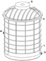
FIG. 1 is a schematic view of the overall structure of the present invention;
FIG. 2 is a front cross-sectional view of the present invention;
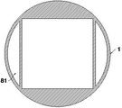
FIG. 3 is a cross-sectional top view of the present invention;
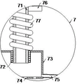
FIG. 4 is an enlarged view of the addition mechanism of the present invention;
FIG. 5 is an enlarged view of the flipping mechanism of the present invention;
FIG. 6 is an enlarged view of the control mechanism of the present invention;
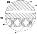
FIG. 7 is an enlarged view of the sweeping mechanism of the present invention;
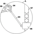
fig. 8 is an enlarged view of the structure at a in fig. 2 according to the present invention.
In the figure: 1. a tank body; 2. a can cover; 3. a water inlet pipe; 4. a water outlet pipe; 5. a feeding port; 61. a collecting groove; 62. a drive rod; 63. connecting blocks; 64. an impeller; 65. a first conical gear; 66. a guide block; 67. a second bevel gear; 68. a first spiral conveying leaf; 69. a second spiral conveying leaf; 7. an adding mechanism; 71. an addition pipe; 72. a bearing; 73. a collection box; 74. a feed opening; 75. a feeding pipe; 76. a first fixing plate; 77. a coil spring; 8. a turning mechanism; 81. collecting tank; 82. filtering with a screen; 83. a second fixing plate; 84. turning the plate; 85. a strip-shaped groove; 86. a partition plate; 87. a reciprocating notch; 88. a nut; 89. a connecting rod; 9. a control mechanism; 91. a groove; 92. a baffle plate; 93. a guide rod; 94. a first spring; 95. a second spring; 10. a sweeping mechanism; 101. a rotating rod; 102. a third fixing plate; 103. and (3) brush hairs.
Detailed Description
The technical solution of the present invention will be clearly and completely described below with reference to the accompanying drawings of the present invention, and the forms of the structures described in the following embodiments are merely examples, and the apparatus for adding disinfectant powder for wastewater treatment according to the present invention is not limited to the structures described in the following embodiments, and all other embodiments obtained by those skilled in the art without creative efforts belong to the protection scope of the present invention.
Referring to fig. 1-4, the invention provides a disinfectant powder feeding device for sewage treatment, which comprises a tank body 1, a tank cover 2 hinged at the top end of the tank body 1, a water inlet pipe 3 and a water outlet pipe 4 fixedly installed on the side wall of the tank body 1, and a feeding port 5 fixedly installed at the upper end of the tank cover 2, wherein a collecting groove 61 is fixedly installed on the inner wall of the tank body 1, a driving rod 62 is rotatably installed between the bottom wall of the tank body 1 and the bottom of the collecting groove 61, two second spiral conveying blades 69 which are symmetrically arranged are rotatably installed on the inner wall of the collecting groove 61, the other ends of the two second spiral conveying blades 69 are fixedly connected with a first spiral conveying blade 68, an adding mechanism 7 for feeding disinfectant powder is arranged between the tank body 1 and the collecting groove 61, and a driving component for driving the first spiral conveying blade 68 is arranged inside the tank body 1;
the adding mechanism 7 comprises two symmetrically arranged adding pipes 71 fixedly arranged at the bottom of the collecting groove 61, bearings 72 are fixedly arranged at the bottom ends of the two adding pipes 71, a collecting box 73 is fixedly arranged on the bearings 72, a plurality of discharging ports 74 are formed in the bottom of the collecting box 73, and a plurality of discharging pipes 75 are fixedly arranged on the side wall of the collecting box 73;
the first fixing plate 76 is fixedly installed on the adding pipe 71, a coil spring 77 is sleeved on the adding pipe 71, and two ends of the coil spring 77 are fixedly connected to the side walls of the collecting tank 73 and the first fixing plate 76 respectively.
Compared with the prior art, the invention has the advantages that through the arrangement of the first spiral conveying blade 68, the second spiral conveying blade 69, the adding pipe 71 and other mechanisms, an operator inputs sewage into the tank body 1 from the water inlet pipe 3, and adds the disinfectant powder from the feed opening 5, then the sewage is discharged from the water outlet pipe 4, the sewage drives the driving assembly to generate power when flowing inside the tank body 1, the driving assembly drives the driving rod 62 to rotate, the driving rod 62 indirectly drives the first spiral conveying blade 68 and the second spiral conveying blade 69 to rotate, the disinfectant powder is conveyed to the top end of the adding pipe 71 and is put into the tank body 1, the collecting box 73 rotates under the self-rotation action of the bearing 72 under the flowing of water, meanwhile, the collecting box 73 drives the plurality of discharging pipes 75 to stir the sewage, the disinfectant powder is mixed into the sewage from the discharging pipes 75 and the feed opening 74 under the flowing of the water, the collecting box 73 is driven to rotate reversely under the rotating force of the coil spring 77, so that the disinfectant powder is fully mixed in the sewage, and the disinfection efficiency of the sewage is accelerated.
Referring to fig. 2, the driving assembly includes a connecting block 63 fixedly mounted on the driving rod 62, a plurality of impellers 64 are fixedly mounted on the connecting block 63, a first conical gear 65 is fixedly mounted at the upper end of the driving rod 62, a second conical gear 67 is fixedly mounted at the other end of each of the two first spiral conveying blades 68, a guide block 66 is sleeved on the driving rod 62, and the other end of each of the two first spiral conveying blades 68 is rotatably mounted on a side wall of the guide block 66.
In the embodiment of the application, by arranging the connecting block 63, the first conical gear 65, the second conical gear 67 and other mechanisms, water flow drives the plurality of impellers 64 to rotate, so as to drive the driving rod 62, the driving rod 62 rotates to drive the first conical gear 65 to rotate, the first conical gear 65 drives the two second conical gears 67 to rotate, so as to drive the first spiral conveying blade 68 and the second spiral conveying blade 69 to rotate, and thus, the first spiral conveying blade 68 and the second spiral conveying blade 69 are driven without electric power.
Refer to fig. 2, fig. 3, fig. 5, fig. 6, fig. 8, be equipped with the mechanism 8 that turns over that is used for turning over impurity on the inner wall of the jar body 1, the mechanism 8 that turns over is including seting up the collecting vat 81 that sets up at jar internal two symmetries of 1 inside, collecting vat 81 bottom and jar internal portion intercommunication department fixed mounting have filter screen 82, fixed mounting has the second fixed plate 83 that two symmetries set up on the inner wall of the jar body 1, it installs turning plate 84 to rotate on two second fixed plates 83, the strip groove 85 has been seted up on the turning plate 84, it installs a plurality of baffles 86 to rotate on the inner wall of strip groove 85, reciprocal notch 87 has been seted up on the actuating lever 62, the nut 88 has been cup jointed on the actuating lever 62, it has a plurality of connecting rods 89 to articulate on the lateral wall of nut 88, the other end of a plurality of connecting rods 89 articulates the bottom at turning plate 84.
In the embodiment of the application, by arranging mechanisms such as the collecting tank 81, the second fixing plate 83 and the turning plate 84, the driving rod 62 rotates to drive the nut 88 to reciprocate up and down in the area where the reciprocating notch 87 is formed, when the nut 88 moves down, the connecting rod 89 is driven to pull the turning plate 84 downwards, the water flow extrudes the partition plates 86 to deflect upwards, the partition plates 86 open the space at the strip-shaped groove 85, so that impurities in sewage rise to the upper side surface of the partition plates 86, when the nut 88 moves up, the connecting rod 89 is driven to push the turning plate 84 upwards, the partition plates 86 are extruded by the gravity of the water flow to be clamped again, the strip-shaped groove 85 is sealed, and the impurities are overturned into the collecting tank 81 when the turning plate 84 deflects upwards, so that the impurities are treated.
Referring to fig. 2 and 6, a control mechanism 9 for controlling impurities to fall into is arranged inside the collecting tank 81, the control mechanism 9 includes a groove 91 formed between the tank body 1 and the collecting tank 81, a baffle 92 is installed inside the groove 91 in a rotating manner, a guide rod 93 is fixedly installed between the inner walls of the collecting tank 81 and the baffle 92, a first spring 94 is sleeved on the guide rod 93, two ends of the first spring 94 are respectively and fixedly connected to the inner walls of the collecting tank 81 and the baffle 92, and a second spring 95 is fixedly connected between the turning plate 84 and the baffle 92.
In the embodiment of the application, through the arrangement of the groove 91, the baffle 92, the first spring 94 and other mechanisms, the flipping board 84 pulls the second spring 95 to stretch when moving downwards, so that the baffle 92 seals the groove 91, the flipping board 84 pushes the baffle 92 to deflect towards the inside of the collecting tank 81 along the guide rod 93 when moving upwards, the groove 91 is opened, impurities can enter the collecting tank 81 smoothly, and then the baffle 92 is pushed to close the groove 91 again under the elastic force action of the first spring 94.
Referring to fig. 2 and 7, a sweeping mechanism 10 for sweeping impurities on the bottom wall of the tank body 1 is arranged at the bottom of the impeller 64, the sweeping mechanism 10 comprises a rotating rod 101 rotatably mounted at the bottom of the impeller 64, a third fixing plate 102 is fixedly mounted at the bottom of the rotating rod 101, bristles 103 are fixedly mounted at the bottom of the third fixing plate 102, and the bristles 103 are staggered with each other.
In the embodiment of the application, the rotating rod 101, the third fixing plate 102, the bristles 103 and other mechanisms are arranged, so that the impeller 64 rotates to drive the third fixing plate 102 to rotate in the tank body 1, the third fixing plate 102 is driven by water flow to rotate, and the bristles 103 are further driven to scrub the bottom wall of the tank body 1, impurities are prevented from being adhered to the bottom wall of the tank body 1, and the influence on the disinfection effect is avoided.
Referring to fig. 5 and 6, the material of the partition 86 and the baffle 92 is butadiene rubber.
In the embodiment of the present application, the butadiene rubber has characteristics of corrosion resistance, oxidation resistance, high strength, etc., so that the partition plate 86 and the baffle plate 92 will not easily corrode and oxidize due to the immersion of the sewage in the tank 1, and the service life of the components is prolonged.
The working principle is as follows:
an operator inputs sewage into the tank body 1 from the water inlet pipe 3, disinfection powder is added from the material adding port 5, then the sewage is discharged from the water outlet pipe 4, the water flow drives the impellers 64 to rotate, further the driving rod 62 is driven, the driving rod 62 rotates to drive the first conical gear 65 to rotate, the first conical gear 65 drives the two second conical gears 67 to rotate, further the first spiral conveying blade 68 and the second spiral conveying blade 69 are driven to rotate, the disinfection powder is conveyed to the top end of the adding pipe 71 and is added into the tank body 1, the collecting box 73 rotates under the self-rotation action of the bearing 72 under the flow of the water flow, meanwhile, the collecting box 73 drives the plurality of discharging pipes 75 to stir the sewage, the disinfection powder is mixed into the sewage from the discharging pipe 75 and the discharging port 74 under the flow of the water flow, the collecting box 73 is driven to rotate under the rotary force of the coil spring 77, the collecting tank 73 is rotated again, the nut 88 is driven by the rotation of the driving rod 62 to move up and down in a reciprocating manner in the area where the reciprocating notch 87 is formed, when the nut 88 moves down, the connecting rod 89 is driven to pull the turning plate 84 downwards, the water flow extrudes the partition plates 86 to deflect upwards, the partition plates 86 open the space of the strip-shaped groove 85, so that impurities in the sewage rise to the upper side surface of the partition plates 86, when the nut 88 moves upwards, the connecting rod 89 is driven to push the turning plate 84 upwards, the gravity of the water flow extrudes the partition plates 86 to clamp the partition plates again, the strip-shaped groove 85 is sealed, when the turning plate 84 moves downwards, the second spring 95 is pulled to stretch, so that the baffle 92 forms a seal for the groove 91, when the turning plate 84 moves upwards, the baffle 92 is pushed to deflect towards the inside of the collecting tank 81 along the guide rod 93, the groove 91 is opened, so that the impurities smoothly enter the collecting tank 81, when the impeller 64 rotates, the third fixing plate 102 is driven to rotate in the tank 1, and the third fixing plate 102 is driven by water flow to rotate, so as to drive the bristles 103 to brush the bottom wall of the tank 1.
The points to be finally explained are: first, in the description of the present application, it should be noted that, unless otherwise specified and limited, the terms "mounted," "connected," and "connected" should be understood broadly, and may be a mechanical connection or an electrical connection, or a communication between two elements, and may be a direct connection, and "upper," "lower," "left," and "right" are only used to indicate a relative positional relationship, and when the absolute position of the object to be described is changed, the relative positional relationship may be changed;
secondly, the method comprises the following steps: in the drawings of the disclosed embodiment of the invention, only the structures related to the disclosed embodiment are related, other structures can refer to common design, and the same embodiment and different embodiments of the invention can be combined mutually under the condition of no conflict;
and finally: the above description is only for the purpose of illustrating the preferred embodiments of the present invention and is not to be construed as limiting the present invention, and any modifications, equivalents, improvements and the like made within the spirit and principle of the present invention should be included in the scope of the present invention.
Claims (5)
1. The utility model provides a throwing equipment of disinfection powder for sewage treatment, includes jar body (1), articulates cover (2) on jar body (1) top, inlet tube (3) and outlet pipe (4) on jar body (1) lateral wall, fixed mounting feed opening (5) in cover (2) upper end, its characterized in that: a gathering groove (61) is fixedly installed on the inner wall of the tank body (1), a driving rod (62) is rotatably installed between the bottom wall of the tank body (1) and the bottom of the gathering groove (61), two second spiral conveying leaves (69) which are symmetrically arranged are rotatably installed on the inner wall of the gathering groove (61), the other ends of the two second spiral conveying leaves (69) are fixedly connected with a first spiral conveying leaf (68), an adding mechanism (7) for adding disinfection powder is arranged between the tank body (1) and the gathering groove (61), and a driving assembly for driving the first spiral conveying leaves (68) is arranged in the tank body (1);
the adding mechanism (7) comprises two symmetrically-arranged adding pipes (71) fixedly mounted at the bottom of the collecting groove (61), bearings (72) are fixedly mounted at the bottom ends of the two adding pipes (71), a collecting box (73) is fixedly mounted on the bearings (72), a plurality of discharging ports (74) are formed in the bottom of the collecting box (73), and a plurality of discharging pipes (75) are fixedly mounted on the side wall of the collecting box (73);
a first fixing plate (76) is fixedly mounted on the adding pipe (71), a coil spring (77) is sleeved on the adding pipe (71), and two ends of the coil spring (77) are respectively and fixedly connected to the side walls of the collecting box (73) and the first fixing plate (76);
drive assembly includes connecting block (63) of fixed mounting on drive lever (62), fixed mounting has a plurality of impellers (64) on connecting block (63), the upper end fixed mounting of drive lever (62) has first conical gear (65), and the equal fixed mounting of the other end of two first spiral delivery leaves (68) has second conical gear (67), guide block (66), two have been cup jointed on drive lever (62) the other end of first spiral delivery leaves (68) is rotated and is installed on the lateral wall of guide block (66).
2. The disinfectant powder adding apparatus for sewage treatment according to claim 1, wherein: be equipped with on the inner wall of the jar body (1) and be used for the mechanism (8) that turn over of turning over impurity, turn over mechanism (8) including seting up at collecting vat (81) that two inside symmetries of the jar body (1) set up, fixed mounting has filter screen (82) with the inside intercommunication department of the jar body (1), fixed mounting has second fixed plate (83) that two symmetries set up on the inner wall of the jar body (1), two rotate on second fixed plate (83) and install turning plate (84), bar groove (85) have been seted up on turning plate (84), rotate on the inner wall of bar groove (85) and install a plurality of baffles (86), reciprocal notch (87) have been seted up on actuating lever (62), nut (88) have been cup jointed on actuating lever (62), it has a plurality of connecting rods (89) to articulate on the lateral wall of nut (88), and is a plurality of the other end of connecting rod (89) articulates the bottom at turning plate (84).
3. The disinfectant powder adding apparatus for sewage treatment according to claim 2, wherein: the inside of collecting vat (81) is equipped with control mechanism (9) that are used for controlling impurity and fall into, control mechanism (9) are including seting up recess (91) between the jar body (1) and collecting vat (81), baffle (92) are installed in the inside rotation of recess (91), fixed mounting has guide bar (93) between the inner wall of collecting vat (81) and baffle (92), first spring (94) have been cup jointed on guide bar (93), and the both ends of first spring (94) are fixed connection respectively on the inner wall of collecting vat (81) and baffle (92), fixedly connected with second spring (95) between upset board (84) and baffle (92).
4. The disinfectant powder adding apparatus for sewage treatment according to claim 1, wherein: the bottom of impeller (64) is equipped with sweeping mechanism (10) that is used for sweeping impurity on jar body (1) diapire, sweeping mechanism (10) is including rotating bull stick (101) of installing in impeller (64) bottom, the bottom fixed mounting of bull stick (101) has third fixed plate (102), the bottom fixed mounting of third fixed plate (102) has brush hair (103), and a plurality of brush hair (103) crisscross each other.
5. The disinfectant powder adding apparatus for sewage treatment according to claim 3, wherein: the partition plate (86) and the baffle plate (92) are made of butadiene rubber.
Priority Applications (1)
| Application Number | Priority Date | Filing Date | Title |
|---|---|---|---|
| CN202211095488.1A CN115159643B (en) | 2022-09-08 | 2022-09-08 | A disinfection powder is thrown and is added equipment for sewage treatment |
Applications Claiming Priority (1)
| Application Number | Priority Date | Filing Date | Title |
|---|---|---|---|
| CN202211095488.1A CN115159643B (en) | 2022-09-08 | 2022-09-08 | A disinfection powder is thrown and is added equipment for sewage treatment |
Publications (2)
| Publication Number | Publication Date |
|---|---|
| CN115159643A CN115159643A (en) | 2022-10-11 |
| CN115159643B true CN115159643B (en) | 2022-11-25 |
Family
ID=83482455
Family Applications (1)
| Application Number | Title | Priority Date | Filing Date |
|---|---|---|---|
| CN202211095488.1A Active CN115159643B (en) | 2022-09-08 | 2022-09-08 | A disinfection powder is thrown and is added equipment for sewage treatment |
Country Status (1)
| Country | Link |
|---|---|
| CN (1) | CN115159643B (en) |
Citations (9)
| Publication number | Priority date | Publication date | Assignee | Title |
|---|---|---|---|---|
| US5350511A (en) * | 1990-01-29 | 1994-09-27 | Yasuyuki Sakurada | Sewage purification apparatus |
| KR100963489B1 (en) * | 2010-01-07 | 2010-06-17 | 덕 용 김 | Supply system of inorganic cohesive agents for cleaning water |
| CN207986771U (en) * | 2017-11-27 | 2018-10-19 | 浙江宏宇环保工程设备有限公司 | A kind of mobile chemicals dosing plant of flocculation aid |
| CN208022759U (en) * | 2017-12-21 | 2018-10-30 | 武汉益恒晟华环保科技有限公司 | A kind of device for handling black and odorous water |
| CN108772017A (en) * | 2018-06-27 | 2018-11-09 | 郑州仁宏医药科技有限公司 | A kind of uniformly mixed agitating device of medical science exploitation |
| CN210313661U (en) * | 2019-02-23 | 2020-04-14 | 新乡市鸣祥线业制造有限公司 | Purifier for printing and dyeing industry |
| CN111517437A (en) * | 2020-05-28 | 2020-08-11 | 葛忠伟 | Energy-saving emission-reducing sewage treatment equipment |
| CN212102138U (en) * | 2020-02-26 | 2020-12-08 | 河南立多可节能科技有限公司 | Sewage treatment ware with disinfectant adds device |
| CN112919600A (en) * | 2021-01-20 | 2021-06-08 | 温州竹魅环保科技有限公司 | Multifunctional sewer sewage treatment device |
-
2022
- 2022-09-08 CN CN202211095488.1A patent/CN115159643B/en active Active
Patent Citations (9)
| Publication number | Priority date | Publication date | Assignee | Title |
|---|---|---|---|---|
| US5350511A (en) * | 1990-01-29 | 1994-09-27 | Yasuyuki Sakurada | Sewage purification apparatus |
| KR100963489B1 (en) * | 2010-01-07 | 2010-06-17 | 덕 용 김 | Supply system of inorganic cohesive agents for cleaning water |
| CN207986771U (en) * | 2017-11-27 | 2018-10-19 | 浙江宏宇环保工程设备有限公司 | A kind of mobile chemicals dosing plant of flocculation aid |
| CN208022759U (en) * | 2017-12-21 | 2018-10-30 | 武汉益恒晟华环保科技有限公司 | A kind of device for handling black and odorous water |
| CN108772017A (en) * | 2018-06-27 | 2018-11-09 | 郑州仁宏医药科技有限公司 | A kind of uniformly mixed agitating device of medical science exploitation |
| CN210313661U (en) * | 2019-02-23 | 2020-04-14 | 新乡市鸣祥线业制造有限公司 | Purifier for printing and dyeing industry |
| CN212102138U (en) * | 2020-02-26 | 2020-12-08 | 河南立多可节能科技有限公司 | Sewage treatment ware with disinfectant adds device |
| CN111517437A (en) * | 2020-05-28 | 2020-08-11 | 葛忠伟 | Energy-saving emission-reducing sewage treatment equipment |
| CN112919600A (en) * | 2021-01-20 | 2021-06-08 | 温州竹魅环保科技有限公司 | Multifunctional sewer sewage treatment device |
Also Published As
| Publication number | Publication date |
|---|---|
| CN115159643A (en) | 2022-10-11 |
Similar Documents
| Publication | Publication Date | Title |
|---|---|---|
| KR101804111B1 (en) | a Water treatment system including pump | |
| CN108773987B (en) | Domestic sewage filter material device | |
| CN211706044U (en) | High efficiency reduces sewage treatment plant that first filter screen blockked up | |
| CN210012692U (en) | Sewage treatment plant for municipal works | |
| CN213112924U (en) | Circulated formula supermagnetic coagulating separator | |
| CN209411911U (en) | Multi-stage aeration pond | |
| CN111617543A (en) | Energy-saving rotary drum type grating machine for sewage treatment | |
| CN112807856B (en) | Algae dross processing apparatus based on special ceramic microsphere | |
| CN115159643B (en) | A disinfection powder is thrown and is added equipment for sewage treatment | |
| KR102251486B1 (en) | A multi-functional air purifying device and air conditioning system including the same | |
| CN211688710U (en) | Water body purification device for removing heavy metals | |
| CN210683261U (en) | Integrated sewage treatment device with solar micro-power | |
| CN209392846U (en) | A kind of filter of easy cleaning | |
| CN111530141A (en) | Automatic sewage treatment filter equipment of clearance | |
| CN209791075U (en) | Gardens sewage treatment plant | |
| CN213537525U (en) | Printing and dyeing sewage filtering device | |
| CN108383314A (en) | A kind of sewage separating device | |
| CN211251435U (en) | Kitchen waste treatment device | |
| CN211676531U (en) | Long-acting water purifier | |
| CN209636012U (en) | A kind of multistage fast sewage treatment device | |
| CN114084970A (en) | Ecological base pan-oxidation pond sewage treatment system | |
| CN112897736A (en) | Sewage treatment device | |
| CN207412873U (en) | Effluent filter | |
| CN110877951A (en) | High-efficient type disinfection pond with filtering capability | |
| CN218988846U (en) | Mountain spring water active carbon filter equipment |
Legal Events
| Date | Code | Title | Description |
|---|---|---|---|
| PB01 | Publication | ||
| PB01 | Publication | ||
| SE01 | Entry into force of request for substantive examination | ||
| SE01 | Entry into force of request for substantive examination | ||
| GR01 | Patent grant | ||
| GR01 | Patent grant |