CN115139028A - Photovoltaic trade welds takes two clamps of area to hold transport mechanism - Google Patents
Photovoltaic trade welds takes two clamps of area to hold transport mechanism Download PDFInfo
- Publication number
- CN115139028A CN115139028A CN202211078716.4A CN202211078716A CN115139028A CN 115139028 A CN115139028 A CN 115139028A CN 202211078716 A CN202211078716 A CN 202211078716A CN 115139028 A CN115139028 A CN 115139028A
- Authority
- CN
- China
- Prior art keywords
- clamp
- clamping
- tail
- guide rail
- pull belt
- Prior art date
- Legal status (The legal status is an assumption and is not a legal conclusion. Google has not performed a legal analysis and makes no representation as to the accuracy of the status listed.)
- Granted
Links
Images


Classifications
-
- B—PERFORMING OPERATIONS; TRANSPORTING
- B23—MACHINE TOOLS; METAL-WORKING NOT OTHERWISE PROVIDED FOR
- B23K—SOLDERING OR UNSOLDERING; WELDING; CLADDING OR PLATING BY SOLDERING OR WELDING; CUTTING BY APPLYING HEAT LOCALLY, e.g. FLAME CUTTING; WORKING BY LASER BEAM
- B23K37/00—Auxiliary devices or processes, not specially adapted to a procedure covered by only one of the preceding main groups
-
- B—PERFORMING OPERATIONS; TRANSPORTING
- B23—MACHINE TOOLS; METAL-WORKING NOT OTHERWISE PROVIDED FOR
- B23K—SOLDERING OR UNSOLDERING; WELDING; CLADDING OR PLATING BY SOLDERING OR WELDING; CUTTING BY APPLYING HEAT LOCALLY, e.g. FLAME CUTTING; WORKING BY LASER BEAM
- B23K2101/00—Articles made by soldering, welding or cutting
- B23K2101/36—Electric or electronic devices
-
- Y—GENERAL TAGGING OF NEW TECHNOLOGICAL DEVELOPMENTS; GENERAL TAGGING OF CROSS-SECTIONAL TECHNOLOGIES SPANNING OVER SEVERAL SECTIONS OF THE IPC; TECHNICAL SUBJECTS COVERED BY FORMER USPC CROSS-REFERENCE ART COLLECTIONS [XRACs] AND DIGESTS
- Y02—TECHNOLOGIES OR APPLICATIONS FOR MITIGATION OR ADAPTATION AGAINST CLIMATE CHANGE
- Y02P—CLIMATE CHANGE MITIGATION TECHNOLOGIES IN THE PRODUCTION OR PROCESSING OF GOODS
- Y02P70/00—Climate change mitigation technologies in the production process for final industrial or consumer products
- Y02P70/50—Manufacturing or production processes characterised by the final manufactured product
Abstract
The invention discloses a welding strip double-clamping and carrying mechanism for a photovoltaic industry, belonging to the technical field of welding processes of superfine welding strips of photovoltaic battery pieces, and particularly relating to a welding strip double-clamping and carrying mechanism for a photovoltaic industry, which comprises a linear module, two lead screw lifting modules arranged on the linear module in a sliding manner, and an A side front carrying clamping mechanism and an A side tail carrying clamping mechanism respectively arranged on the lifting ends of the two lead screw lifting modules, wherein the two lead screw lifting modules are used for respectively driving the A side front carrying clamping mechanism and the A side tail carrying clamping mechanism to lift for height adjustment, and the linear module is used for driving the lead screw lifting modules to axially move.
Description
Technical Field
The invention relates to the technical field of welding processes of superfine welding strips of photovoltaic battery pieces, in particular to a double-clamping and carrying mechanism for welding strips in the photovoltaic industry.
Background
In the existing battery piece multi-main-grid series welding process, a welding strip is clamped from a cutter through a lever structure clamped up and down, the welding strip is horizontally driven by a servo module to be pulled to the position above a battery piece, a rear-end welding strip is flatly laid on a heating platform, and a four-axis robot places the battery piece subjected to vacuum adsorption on the rear-end welding strip and repeats the actions;
however, the welding strip is more and thinner when the series welding machine is required to work by a new process, the welding strip is more and more bent after being cut off more and more, and the circular welding strip with the diameter of less than 0.25MM is called as an ultra-fine welding strip in the photovoltaic industry.
Disclosure of Invention
The invention aims to provide a double-clamping and carrying mechanism for a solder strip in the photovoltaic industry, which aims to solve the problems that when the solder strip and a battery piece are laid due to the fact that an ultra-fine solder strip is bent after being cut by a cutter, the solder strip and a main grid line of the battery piece are not in the same straight line, grid deviation and overlapping are poor, excessive insufficient soldering and white exposure are caused after series welding, and the defective rate is too high to produce.
In order to achieve the purpose, the invention provides the following technical scheme: the utility model provides a two centre gripping transport mechanisms of photovoltaic trade solder strip, includes sharp module, slides and establishes two lead screw lift modules on sharp module, establishes transport fixture and A side tail transport fixture before the A side on two lead screw lift module lift ends respectively, two lead screw lift module is used for driving a side before transport fixture and A side tail transport fixture lift respectively and carries out the altitude mixture control, and sharp module is used for driving lead screw lift module and carries out axial displacement.
Preferably, the A-side front carrying and clamping mechanism comprises a pre-clamping cylinder and two stressing cylinders which are installed in the box body, a chuck main body and a linear guide rail III which are arranged on the outer wall of the box body, the chuck main body comprises a belt pulling clamp, a spring I, a short belt pulling clamp and a long belt pulling clamp, the chuck main body and the belt pulling clamp are both installed on the linear guide rail III, the telescopic end of the stressing cylinder is connected with the chuck main body, the short belt pulling clamp and the long belt pulling clamp are both installed in the chuck main body through movable shafts, and the spring I is used for pressing the short belt pulling clamp and the long belt pulling clamp.
Preferably, the A side tail carrying and clamping mechanism comprises a clamping cylinder, a first linear guide rail, a second linear guide rail, a tail clamp push plate and a pull clamp grab, wherein the clamping cylinder is arranged on the mounting frame, the tail clamp push plate is arranged on the first linear guide rail and the second linear guide rail in a sliding mode, the pull clamp grab is arranged on the tail clamp push plate, and the telescopic end of the clamping cylinder is connected with the tail clamp push plate.
Preferably, the number of the belt pulling clamps is not less than one, the two belt pulling clamps form a group, and a second spring is arranged between the two belt pulling clamps.
Preferably, the telescopic end of the pre-clamping cylinder is connected with the pull belt clamp.
Compared with the prior art, the invention has the beneficial effects that:
1) The welding strip double-clamping structure for the series welding machine ensures that the welding strip is always in a stretched state in the movement process, the welding strip is not deformed in the movement process, the welding precision of the welding strip relative to a battery piece is greatly improved, and meanwhile, the welding strip clamping structure can reduce defects of insufficient solder, white exposure and the like of the battery piece after series welding.
2) The invention can be applied to the cell with 24 grid lines, fills the gap in the current market, greatly improves the efficiency of the equipment and increases the compatibility of the equipment to the grid lines of the cell.
Drawings
FIG. 1 is a schematic structural view of the present invention;
FIG. 2 is a schematic view of a clamping solder strip structure according to the present invention;
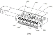
FIG. 3 is a schematic structural view of a side A front carrying and clamping mechanism of the present invention;
FIG. 4 is a schematic structural view of a side tail conveying and clamping mechanism of the invention A.
In the figure: 100. a linear module; 200. a screw rod lifting module; 300. a side A front carrying and clamping mechanism; 301. pre-clamping a cylinder; 302. a boosting cylinder; 303. a third linear guide rail; 304. a tension spring; 305. pulling the belt clip; 306. a first spring; 307. a short pull belt clip; 308. a long tension band clamp; 309. a chuck body; 400. a, carrying and clamping a mechanism at the tail of the side; 401. a clamping cylinder; 402. a first linear guide rail; 403. a second linear guide rail; 404. pulling the belt and clamping the belt; 405. a second spring; 406. a tail clip push plate.
Detailed Description
The technical solutions in the embodiments of the present invention will be clearly and completely described below with reference to the drawings in the embodiments of the present invention, and it is obvious that the described embodiments are only a part of the embodiments of the present invention, and not all of the embodiments. All other embodiments, which can be obtained by a person skilled in the art without making any creative effort based on the embodiments in the present invention, belong to the protection scope of the present invention.
In the description of the present invention, it is to be understood that the terms "upper", "lower", "front", "rear", "left", "right", "top", "bottom", "inner", "outer", and the like, indicate orientations or positional relationships based on the orientations or positional relationships shown in the drawings, are merely for convenience in describing the present invention and simplifying the description, and do not indicate or imply that the device or element being referred to must have a particular orientation, be constructed and operated in a particular orientation, and thus, should not be construed as limiting the present invention.
Example (b):
referring to fig. 1-4, the present invention provides a technical solution: the utility model provides a two centre gripping transport mechanisms of photovoltaic trade solder strip, includes sharp module 100, slides and establishes two lead screw lifting module 200 on sharp module 100, establishes respectively and carries fixture 300 and A side tail transport fixture 400 before the A side on two lead screw lifting module 200 lift ends, two lead screw lifting module 200 is used for carrying fixture 300 and A side tail transport fixture 400 lift before driving the A side respectively and carries out the altitude mixture control, and sharp module 100 is used for driving lead screw lifting module 200 and carries out axial displacement.
The a-side front carrying clamping mechanism 300 comprises a pre-clamping cylinder 301 and two force application cylinders 302 which are installed in a box body, a clamp body 309 and a linear guide rail III 303 which are arranged on the outer wall of the box body, the clamp body 309 comprises a pull belt clamp 305, a spring I306, a short pull belt clamp 307 and a long pull belt clamp 308, the clamp body 309 and the pull belt clamp 305 are both installed on the linear guide rail III 303, the telescopic end of the force application cylinder 302 is connected with the clamp body 309, the short pull belt clamp 307 and the long pull belt clamp 308 are both installed in the clamp body 309 through movable shafts, the spring I306 is used for pressing the short pull belt clamp 307 and the long pull belt clamp 308, when the cylinders do not work, the a-side front carrying clamping mechanism 300 is in an open state, when the a-side front carrying clamping mechanism 300 needs to clamp a welding belt, the pre-clamping cylinder 301 drives the pull belt clamp 305, the left-side force application cylinders 302 and the right-side force application cylinders 302 work simultaneously to drive the short clamp 307 and the long clamp 308 which are fixed on the clamp body 309 to clamp the welding belt, and 304 in fig. 3 is a tension spring 301 which is used for connecting the pull belt clamp 305 and playing a role of pulling the pull belt clamp 305.
The A-side tail carrying and clamping mechanism 400 comprises a clamping cylinder 401, a first linear guide rail 402, a second linear guide rail 403, a tail clamp push plate 406 and a belt pulling clamp grab 404, wherein the clamping cylinder 401, the first linear guide rail 402, the second linear guide rail 403, the tail clamp push plate 406 and the belt pulling clamp grab 404 are arranged on the first linear guide rail 402 and the second linear guide rail 403 respectively in a sliding mode, the telescopic end of the clamping cylinder 401 is connected with the tail clamp push plate 406, the number of the belt pulling clamp grabs 404 is not less than one, the two belt pulling clamp grabs 404 form a group, a second spring 405 is arranged between the two belt pulling clamp grabs 404, the telescopic end of the pre-clamping cylinder 301 is connected with the belt pulling clamp 305, when the tail carrying and clamping mechanism needs to clamp a welding belt, the clamping cylinder 401 pushes a connecting plate connected with the tail clamp push plate 406, the movement in the X-axis direction is converted into the movement in the Y-direction, and the two belt pulling clamp grabs 404 are pushed to clamp the welding belt at the same time.
The working principle is as follows: the A-side front carrying and clamping mechanism 300 moves to a cutting knife to clamp a welding strip (the pre-clamping cylinder 301 and the stressing cylinder 302 act respectively), the A-side linear module 100 pulls the welding strip to move forwards for a certain distance, the cutting knife (not shown in the figures, the mechanism does not belong to the technical scheme of the application, and only works in cooperation with the application) starts to cut off the welding strip, the A-side tail carrying and clamping mechanism 400 starts to descend to clamp the welding strip, the A-side front carrying and clamping mechanism 300 and the A-side tail carrying and clamping mechanism 400 simultaneously clamp the head end and the tail end of the welding strip, a double-acting-rotor driving double-clamping mechanism (referring to the A-side front carrying and clamping mechanism 300 and the A-side tail carrying and clamping mechanism 400) on the linear module 100 (equivalent to an X-axis workbench) carries the welding strip to reach an appointed position, and the double-clamping mechanism is always in a straight state in the carrying process of clamping the welding strip, deformation and deflection are guaranteed in the welding strip moving process and do not stretch until the welding strip is sent to the appointed position of a heating platform. At this moment, the a-side tail carrying clamping mechanism 400 loosens the welding strip and leaves, a module below the marble of the heating platform (not shown in the figure, the mechanism does not belong to the technical scheme of the application and only works in cooperation with the application) starts to ascend, one end of the welding strip is loosened by the a-side tail carrying clamping mechanism 400, the tail end of the welding strip is clamped, then the welding strip is straightened, and the action process is that the welding strip is always straightened to reach a straight line state. The double clamping mechanisms clamp the welding strip and move downwards to be close to the grid line of the battery piece, at the same time, the four-axis robot presses the pressure welding jig to position the welding strip, the welding strip is attached to the battery piece, the front carrying clamping mechanism 300 on the A side (the pre-clamping cylinder 301 and the stressing cylinder 302 move simultaneously to release the welding strip) and the tail clamp of the heating platform release the welding strip to fall to a specified position, the position avoiding platform moves, the lead screw lifting module 200 drives the clamping mechanisms to rise, and the linear module 100 mover sends the tail carrying clamping mechanism 400 on the A side back to the cutter to clamp the welding strip; the above actions are repeated. A. The two sides of B move reciprocally and alternately.
While there have been shown and described the fundamental principles and essential features of the invention and advantages thereof, it will be apparent to those skilled in the art that the invention is not limited to the details of the foregoing exemplary embodiments, but is capable of other specific forms without departing from the spirit or essential characteristics thereof; the present embodiments are therefore to be considered in all respects as illustrative and not restrictive, the scope of the invention being indicated by the appended claims rather than by the foregoing description, and all changes which come within the meaning and range of equivalency of the claims are therefore intended to be embraced therein, and any reference signs in the claims are not intended to be construed as limiting the claim concerned.
Although embodiments of the present invention have been shown and described, it will be appreciated by those skilled in the art that changes, modifications, substitutions and alterations can be made in these embodiments without departing from the principles and spirit of the invention, the scope of which is defined in the appended claims and their equivalents.
Claims (5)
1. The utility model provides a two centre gripping transport mechanisms of photovoltaic trade solder strip which characterized in that: including sharp module (100), slide two lead screw lifting module (200) of establishing on sharp module (100), establish respectively before A side transport fixture (300) and A side tail transport fixture (400) on two lead screw lifting module (200) lift ends lead screw lifting module (200) are used for driving respectively that transport fixture (300) and A side tail transport fixture (400) go up and down and carry out the altitude mixture control before A side carries fixture (300) and A side tail, and sharp module (100) are used for driving lead screw lifting module (200) and carry out axial displacement.
2. The photovoltaic industry solder strip double-clamping handling mechanism of claim 1, characterized in that: the A-side front carrying clamping mechanism (300) comprises a pre-clamping cylinder (301) and two force application cylinders (302) which are installed in a box body, a chuck main body (309) and a linear guide rail III (303) which are arranged on the outer wall of the box body, wherein the chuck main body (309) comprises a pull belt clamp (305), a first spring (306), a short pull belt clamp (307) and a long pull belt clamp (308), the chuck main body (309) and the pull belt clamp (305) are installed on the linear guide rail III (303), the telescopic end of the force application cylinder (302) is connected with the chuck main body (309), the short pull belt clamp (307) and the long pull belt clamp (308) are installed in the chuck main body (309) through movable shafts, and the first spring (306) is used for pressing the short pull belt clamp (307) and the long pull belt clamp (308).
3. The photovoltaic industry solder strip double-clamping handling mechanism of claim 1, characterized in that: the A-side tail carrying and clamping mechanism (400) comprises a clamping cylinder (401), a linear guide rail I (402), a linear guide rail II (403), a tail clamp push plate (406) and a pull belt clamp grab (404), wherein the clamping cylinder (401), the linear guide rail I (402), the linear guide rail II (403) are arranged on a mounting frame in a sliding mode, the pull belt clamp push plate (406) is arranged on the tail clamp push plate (406), and the telescopic end of the clamping cylinder (401) is connected with the tail clamp push plate (406).
4. The photovoltaic industry solder strip double-clamping handling mechanism of claim 3, characterized in that: the number of the belt pulling clamp claws (404) is not less than one, two belt pulling clamp claws (404) form a group, and a second spring (405) is arranged between the two belt pulling clamp claws (404).
5. The photovoltaic industry solder strip double-clamping handling mechanism of claim 2, characterized in that: the telescopic end of the pre-clamping cylinder (301) is connected with a draw belt clamp (305).
Priority Applications (1)
| Application Number | Priority Date | Filing Date | Title |
|---|---|---|---|
| CN202211078716.4A CN115139028B (en) | 2022-09-05 | 2022-09-05 | Photovoltaic trade welds takes two clamps of area to hold transport mechanism |
Applications Claiming Priority (1)
| Application Number | Priority Date | Filing Date | Title |
|---|---|---|---|
| CN202211078716.4A CN115139028B (en) | 2022-09-05 | 2022-09-05 | Photovoltaic trade welds takes two clamps of area to hold transport mechanism |
Publications (2)
| Publication Number | Publication Date |
|---|---|
| CN115139028A true CN115139028A (en) | 2022-10-04 |
| CN115139028B CN115139028B (en) | 2022-11-29 |
Family
ID=83415845
Family Applications (1)
| Application Number | Title | Priority Date | Filing Date |
|---|---|---|---|
| CN202211078716.4A Active CN115139028B (en) | 2022-09-05 | 2022-09-05 | Photovoltaic trade welds takes two clamps of area to hold transport mechanism |
Country Status (1)
| Country | Link |
|---|---|
| CN (1) | CN115139028B (en) |
Cited By (2)
| Publication number | Priority date | Publication date | Assignee | Title |
|---|---|---|---|---|
| CN116214063A (en) * | 2023-02-21 | 2023-06-06 | 连城凯克斯科技有限公司 | Welding strip stretching device of series welding machine |
| CN116525531A (en) * | 2023-07-05 | 2023-08-01 | 深圳光远智能装备股份有限公司 | Clamping mechanism and series welding device applied to high-density welding strip of battery piece |
Citations (5)
| Publication number | Priority date | Publication date | Assignee | Title |
|---|---|---|---|---|
| US20110147437A1 (en) * | 2009-12-22 | 2011-06-23 | Kioto Photovoltaics Gmbh | Device for fixing conductor tracks on a solar cell |
| CN104084730A (en) * | 2014-04-02 | 2014-10-08 | 太原风华信息装备股份有限公司 | Cell positioning mechanism of solar cell serial welding machine |
| CN110391316A (en) * | 2019-07-23 | 2019-10-29 | 杭州康奋威科技股份有限公司 | A kind of automatic preparation facilities of L-C shape busbar and its busbar preparation method |
| CN113471335A (en) * | 2021-07-19 | 2021-10-01 | 杭州康奋威科技股份有限公司 | Battery string production line |
| CN217122035U (en) * | 2022-01-29 | 2022-08-05 | 浙江隆基乐叶光伏科技有限公司 | Welding strip clamping jaw and series welding machine |
-
2022
- 2022-09-05 CN CN202211078716.4A patent/CN115139028B/en active Active
Patent Citations (5)
| Publication number | Priority date | Publication date | Assignee | Title |
|---|---|---|---|---|
| US20110147437A1 (en) * | 2009-12-22 | 2011-06-23 | Kioto Photovoltaics Gmbh | Device for fixing conductor tracks on a solar cell |
| CN104084730A (en) * | 2014-04-02 | 2014-10-08 | 太原风华信息装备股份有限公司 | Cell positioning mechanism of solar cell serial welding machine |
| CN110391316A (en) * | 2019-07-23 | 2019-10-29 | 杭州康奋威科技股份有限公司 | A kind of automatic preparation facilities of L-C shape busbar and its busbar preparation method |
| CN113471335A (en) * | 2021-07-19 | 2021-10-01 | 杭州康奋威科技股份有限公司 | Battery string production line |
| CN217122035U (en) * | 2022-01-29 | 2022-08-05 | 浙江隆基乐叶光伏科技有限公司 | Welding strip clamping jaw and series welding machine |
Cited By (4)
| Publication number | Priority date | Publication date | Assignee | Title |
|---|---|---|---|---|
| CN116214063A (en) * | 2023-02-21 | 2023-06-06 | 连城凯克斯科技有限公司 | Welding strip stretching device of series welding machine |
| CN116214063B (en) * | 2023-02-21 | 2024-02-23 | 连城凯克斯科技有限公司 | Welding strip stretching device of series welding machine |
| CN116525531A (en) * | 2023-07-05 | 2023-08-01 | 深圳光远智能装备股份有限公司 | Clamping mechanism and series welding device applied to high-density welding strip of battery piece |
| CN116525531B (en) * | 2023-07-05 | 2023-09-15 | 深圳光远智能装备股份有限公司 | Clamping mechanism and series welding device applied to high-density welding strip of battery piece |
Also Published As
| Publication number | Publication date |
|---|---|
| CN115139028B (en) | 2022-11-29 |
Similar Documents
| Publication | Publication Date | Title |
|---|---|---|
| CN115139028B (en) | Photovoltaic trade welds takes two clamps of area to hold transport mechanism | |
| WO2018171275A1 (en) | Busbar feeding mechanism and feeding method, and stringer having busbar feeding mechanism | |
| CN208054400U (en) | A kind of lithium battery electric core transplantation device | |
| CN113744998A (en) | Automatic foot winding machine | |
| CN111463324A (en) | Multi-main-grid photovoltaic cell and welding strip positioning equipment | |
| CN113838949A (en) | Solar panel lead-out wire placer | |
| CN113555756B (en) | Full-automatic wire stripping and welding production line equipment for electronic wire | |
| CN210589452U (en) | Insulating strip cutting equipment | |
| CN104416358A (en) | Wire drawing and cutting device | |
| CN219746809U (en) | Terminal connection wire harness welding machine | |
| CN209993582U (en) | Solar cell string bus bar pulling and steering device | |
| CN203621900U (en) | Wire drawing and cutting device | |
| CN217193145U (en) | Welding strip clamping device for series welding machine | |
| CN217529716U (en) | Heating belt mechanism with telescopic lamination for series welding machine | |
| CN110002071A (en) | Automatic labeling equipment | |
| CN110768490B (en) | Rapid transportation formula wire winding production line | |
| CN210403755U (en) | Solar cell series welding bus bar pulling device | |
| CN212823247U (en) | Automatic tin soldering machine | |
| CN115057285A (en) | Solder strip traction device and traction method | |
| CN209736513U (en) | Cylindrical capacitor double-pin synchronous bending and shaping equipment | |
| CN111055008A (en) | Feeding device and welding system | |
| CN220856656U (en) | Strip-shaped cell tab bending pre-welding transmission line | |
| CN219520785U (en) | Automatic chip welding machine | |
| CN210160553U (en) | Wire pulling structure of full-automatic lamp strip wire welding machine | |
| CN219601805U (en) | Single clamping jaw tears winding displacement membrane mechanism |
Legal Events
| Date | Code | Title | Description |
|---|---|---|---|
| PB01 | Publication | ||
| PB01 | Publication | ||
| SE01 | Entry into force of request for substantive examination | ||
| SE01 | Entry into force of request for substantive examination | ||
| GR01 | Patent grant | ||
| GR01 | Patent grant |