CN115095665A - Self-adaptive split type sealing device - Google Patents
Self-adaptive split type sealing device Download PDFInfo
- Publication number
- CN115095665A CN115095665A CN202210863070.4A CN202210863070A CN115095665A CN 115095665 A CN115095665 A CN 115095665A CN 202210863070 A CN202210863070 A CN 202210863070A CN 115095665 A CN115095665 A CN 115095665A
- Authority
- CN
- China
- Prior art keywords
- ring
- elastic sealing
- sides
- sealing ring
- self
- Prior art date
- Legal status (The legal status is an assumption and is not a legal conclusion. Google has not performed a legal analysis and makes no representation as to the accuracy of the status listed.)
- Pending
Links
Images


Classifications
-
- F—MECHANICAL ENGINEERING; LIGHTING; HEATING; WEAPONS; BLASTING
- F16—ENGINEERING ELEMENTS AND UNITS; GENERAL MEASURES FOR PRODUCING AND MAINTAINING EFFECTIVE FUNCTIONING OF MACHINES OR INSTALLATIONS; THERMAL INSULATION IN GENERAL
- F16J—PISTONS; CYLINDERS; SEALINGS
- F16J15/00—Sealings
- F16J15/16—Sealings between relatively-moving surfaces
- F16J15/34—Sealings between relatively-moving surfaces with slip-ring pressed against a more or less radial face on one member
- F16J15/3464—Mounting of the seal
-
- F—MECHANICAL ENGINEERING; LIGHTING; HEATING; WEAPONS; BLASTING
- F16—ENGINEERING ELEMENTS AND UNITS; GENERAL MEASURES FOR PRODUCING AND MAINTAINING EFFECTIVE FUNCTIONING OF MACHINES OR INSTALLATIONS; THERMAL INSULATION IN GENERAL
- F16J—PISTONS; CYLINDERS; SEALINGS
- F16J15/00—Sealings
- F16J15/16—Sealings between relatively-moving surfaces
- F16J15/32—Sealings between relatively-moving surfaces with elastic sealings, e.g. O-rings
- F16J15/3268—Mounting of sealing rings
-
- F—MECHANICAL ENGINEERING; LIGHTING; HEATING; WEAPONS; BLASTING
- F16—ENGINEERING ELEMENTS AND UNITS; GENERAL MEASURES FOR PRODUCING AND MAINTAINING EFFECTIVE FUNCTIONING OF MACHINES OR INSTALLATIONS; THERMAL INSULATION IN GENERAL
- F16J—PISTONS; CYLINDERS; SEALINGS
- F16J15/00—Sealings
- F16J15/16—Sealings between relatively-moving surfaces
- F16J15/32—Sealings between relatively-moving surfaces with elastic sealings, e.g. O-rings
- F16J15/3284—Sealings between relatively-moving surfaces with elastic sealings, e.g. O-rings characterised by their structure; Selection of materials
Landscapes
- Engineering & Computer Science (AREA)
- General Engineering & Computer Science (AREA)
- Mechanical Engineering (AREA)
- Sealing Devices (AREA)
Abstract
The invention relates to the field of sealing, in particular to a self-adaptive split type sealing device which comprises a movable ring and a static ring part, wherein the movable ring and the static ring part are connected in a sliding sealing manner, an elastic sealing ring is arranged on the movable ring, bulges are distributed on the outer side of the elastic sealing ring in a circumferential manner, the elastic sealing ring is positioned in the movable ring in an extrusion manner, abdicating grooves corresponding to the bulges one by one are formed in the movable ring, the static part is in a shell shape, the movable ring is positioned in the static part, and two sides of the movable ring are connected with the inner wall of the static part in a sliding sealing manner. Adopt elastic sealing ring can be on equipment main shaft freely adjust the position, do not need the distance to install, compare prior art, the simple structure of adopting in this scheme, easily dismantle the maintenance, be favorable to control cost.
Description
Technical Field
The invention relates to the field of sealing, in particular to a self-adaptive split type sealing device.
Background
In the production process of food, chemical industry, mineral products and pharmacy, a plurality of mixing, extruding and stirring devices are needed, and in order to avoid material leakage in the production process, a sealing device is generally adopted to solve the problem of sealing of the power rotating part and the bin connecting part on the device.
Chinese patent No. CN211951436U discloses a combined stationary ring type rotary shaft seal, which includes a hoop, a shaft sleeve, a moving ring, and a combined stationary ring set, wherein the hoop needs to be installed first with a main shaft of an apparatus in actual operation, which has the following disadvantages: need the clamp fixed back, just can be with the axle sleeve, the rotating ring, and quiet ring suit of combination formula and clamp adaptation installation, the position of clamp must be fixed in advance to sealing device's integral erection, on the contrary, finish when sealing device integral erection, if continue to change overall position then be difficult to realize the clamp adjustment, form the distance installation that has the limitation, in addition, because the device utilizes the clamp transmission, there is the driven structure of adaptation clamp, the structure is more complicated, further lead to that the position that later maintenance needs to be dismantled is more, be unfavorable for control cost.
In view of the above, we propose an adaptive split seal.
Disclosure of Invention
In order to solve the problems that the installation needs to be carried out at a fixed distance and the structure is complex and difficult to maintain in the prior art, the invention provides the self-adaptive split type sealing device.
Split type sealing device of self-adaptation, be sliding seal form including rotating ring and quiet portion and both and connect, the last elastic sealing ring of rotating ring, there is the arch of circumference distribution in the elastic sealing ring outside, elastic sealing ring is inside extrusion form is located the rotating ring, has the groove of stepping down with protruding one-to-one on the rotating ring, quiet portion is shell form and rotating ring and is located quiet portion, and the rotating ring both sides are sliding seal form with quiet portion inner wall and are connected.
Preferably, the rotating ring is of a split structure, and comprises a first ring and a second ring which are the same in shape and are positioned on two sides of the elastic sealing ring, wherein one side of the first ring and one side of the second ring, which are close to the elastic sealing ring, are provided with annular gaps for extruding the elastic sealing ring, the width of each gap is smaller than half of the width of the elastic sealing ring, and the abdicating grooves are distributed on the gaps and form an integral structure with the gaps.
Preferably, the static part comprises a cylindrical fixing seat and a cylindrical gland, the fixing seat and the gland are connected through a countersunk head bolt, static rings are arranged on the inner walls of the fixing seat and the gland, one opposite sides of the static rings are connected with the movable ring in a sliding sealing mode, and when the elastic sealing ring is in an extrusion state with the first ring and the second ring on the two sides, the distance between the first ring and the second ring is 0.5-1 mm.
Preferably, the surface of the static ring and the dynamic ring close to each other is a smooth finish surface.
Preferably, the fixing seat and the gland are fixedly connected through a bolt, an annular groove is formed between binding surfaces of the fixing seat and the gland, and a sealing ring is installed in the annular groove and used for sealing between the fixing seat and the gland.
Preferably, annular oil grooves are concentrically arranged on two sides of the movable ring, and lubricating oil is contained in the oil grooves so as to seep out of the oil grooves to reduce friction between the two.
Preferably, the fixing seat, the gland, the stationary ring, the first ring and the second ring are of a combined structure formed by splicing two semicircular ring pieces, through holes are formed in the two semicircular ring pieces along arc-shaped surfaces on two sides of the two semicircular ring pieces in the tangential direction, the through hole of one semicircular piece is a countersunk hole, a countersunk bolt penetrates into the countersunk hole, one end of the countersunk bolt penetrates into the through hole of the other semicircular ring piece and then is fastened and connected through a nut, and the countersunk bolt and the nut are fully embedded into the through hole.
Preferably, the cross-sectional shape of the elastic sealing ring is matched with the cross-sectional shapes of the notches on the movable rings at two sides, and elastic convex belts are further arranged at two sides of the inner wall of the elastic sealing ring, so that the main shaft can prop the elastic sealing ring to the two sides after pressing the elastic convex belts.
The invention has the beneficial effects that: above-mentioned scheme is equipped with elastic sealing ring, and the cover has the rotating ring on the elastic sealing ring, and the cover has quiet portion on the rotating ring, and when quiet portion and equipment rigid coupling and elastic sealing ring link to each other with the main shaft, this sealing device can be along the main shaft free position regulation, does not need the distance to install, compares prior art, and the structure of adopting in this scheme is more simple, and easy to detach maintains, only needs to change ageing elastic sealing ring, is favorable to control cost.
Drawings
FIG. 1 is a schematic view of the overall structure of the present invention;
FIG. 2 is a schematic diagram of the exploded structure of the various parts of the apparatus;
FIG. 3 is a schematic cross-sectional view of the present invention;
FIG. 4 is a schematic structural view of an elastic sealing ring;
FIG. 5 is a schematic structural view of the rotating ring;
FIG. 6 is a rear view of the structure of FIG. 5;
fig. 7 is a schematic structural view of a stationary ring.
Detailed Description
The technical solutions in the embodiments of the present invention will be clearly and completely described below with reference to the drawings in the embodiments of the present invention, and it is obvious that the described embodiments are only a part of the embodiments of the present invention, and not all of the embodiments.
Example 1: in this embodiment, split type sealing device of self-adaptation, including rotating ring 2 and quiet portion and both are sliding seal and describe the connection, elastic sealing ring 1 on the rotating ring 2, there is the arch 101 of circumference distribution outside elastic sealing ring 1, inside elastic sealing ring 1 was the extrusion and describes and is located rotating ring 2, have the groove 2001 of stepping down with protruding 101 one-to-one on the rotating ring 2, quiet portion is the shell form and rotating ring 2 is located quiet portion, and the rotating ring 2 both sides are sliding seal and describe with quiet portion inner wall and are connected. The movable ring 2 and the elastic sealing ring 1 are in a linkage structure through the protrusions 101 on the elastic sealing ring 1, the elastic sealing ring 1 does not need to be installed on the equipment main shaft firstly, and the movable ring can be directly sleeved and pressed on the equipment main shaft after a sealing device is installed in advance, so that the installation steps are simplified.
Specifically, four protrusions 101 are uniformly arranged on the elastic sealing ring 1 along the outer side of the ring wall, and correspondingly, the movable ring 2, namely the ring one 201 and the ring two 202, are respectively provided with an annular notch 2002 matched with the elastic sealing ring 1, and the annular notch 2002 is provided with four abdicating grooves 2001, when the ring one 201 and the ring two 202 compress the elastic sealing ring 1 from two sides, the elastic sealing ring 1 and the protrusions 101 extend into the notch 2002 and the abdicating grooves 2001 together, and at the moment, the elastic sealing ring 1 and the movable ring 2 are relatively fixed, so that positioning is realized.
Example 2: in this embodiment, as shown in fig. 1 to 5, the movable ring 2 is a split structure, and includes a first ring 201 and a second ring 202 that have the same shape and are located at two sides of the elastic sealing ring 1, and both sides of the first ring 201 and the second ring 202 close to the elastic sealing ring 1 are provided with an annular notch 2002 for extruding the elastic sealing ring 1, a width of the notch 2002 is less than a half of a width of the elastic sealing ring 1, the relief grooves 2001 are distributed on the notch 2002 and form an integrated structure with the notch 2002, and the notch 2002 is configured to fix the elastic sealing ring 1 and ensure a sealing effect by extruding the elastic sealing ring 1.
Furthermore, two sides of the inner wall of the elastic sealing ring 1 are further provided with elastic convex belts 102, so that the main shaft presses the elastic convex belts 102 to expand the elastic sealing ring 1 to two sides, and two sides of the elastic sealing ring 1 are pressed on the notch 2002 to form sealing.
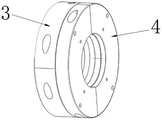
Example 3: in this embodiment, quiet portion is formed by fixing base 3 and gland 4 fixed connection, and fixing base 3 and gland 4 are the tube-shape, and its center has the adaptation hole that is used for the main shaft to penetrate, through the equal fixedly connected with quiet ring 5 of bolt on fixing base 3 and the 4 inner walls of gland, and quiet ring 5 opposite side is connected with rotating ring 2 and is the sliding seal form.
In this embodiment, the both sides of ring one 201 and ring two 202 are compressed tightly by quiet ring 5, and further, the one side that quiet ring 5 and rotating ring 2 are close to each other is smooth finish machining face for reduce frictional force between the two, and then increase of service life, and further, fixing base 3 and gland 4 link firmly through the bolt and are equipped with annular 301 that is used for installing the sealing washer between binding face between the two, are used for guaranteeing the sealed effect between fixing base 3 and the gland 4 behind the installation sealing washer.
After the sealing device is installed, the elastic sealing ring 1 is pressed by the first ring 201 and the second ring 202, and two sides of the first ring 201 and the second ring 202 are pressed by the static ring 5, at this time, the distance between the first ring 201 and the second ring 202 is 0.5-1mm, if the distance is too large, the connection of the sealing device is too loose, and if the distance is too small, the connection is too tight, and the transmission effect is deteriorated in both cases.
Example 3: as shown in fig. 2, 3 or 5, two sides of the moving ring 2 (ring one 201 and ring two 202 in the figure) are concentrically provided with annular oil grooves, and the oil grooves are used for quantitatively storing lubricating oil and ensuring the lubricating effect of the moving ring 2 and the stationary ring 5 in the relative movement process, so that the service life of parts is further prolonged.
In the invention, as shown in fig. 1-3 or fig. 5-7, the structures of the fixed seat 3, the gland 4, the stationary ring 5, the ring one 201 and the ring two 202 are all combined structures formed by splicing two semicircular ring pieces, and the two semicircular ring pieces are fixedly connected through bolts after being combined.
It should be noted that through holes are tangentially formed in the arc-shaped surfaces of the two sides of the two semicircular ring pieces, the through hole of one semicircular piece is a countersunk hole, a countersunk bolt penetrates into the countersunk hole, one end of the countersunk bolt penetrates into the through hole of the other semicircular ring piece and then is fastened and connected through a nut, and the countersunk bolt and the nut are completely embedded into the through hole, namely the countersunk bolt and the nut are hidden by the through hole.
Specifically, the cross-sectional shape of the elastic sealing ring 1 is matched with the cross-sectional shape of the notches 2002 on the two side moving rings 2, so that the elastic sealing ring 1 is approximately attached to the notches 2002 when being pressed.
In the invention, the static ring 5 is provided with the countersunk holes and is in threaded connection with the inner wall of the fixed seat 3 through the countersunk bolts, similarly, the static ring 5 is also fixedly connected with the gland 4 through the countersunk bolts, the structures of the fixed seat 3, the gland 4, the static ring 5, the ring I201 and the ring II 202 are combined structures formed by splicing two semicircular ring pieces, and two countersunk holes are respectively arranged on two semicircular ring pieces in each static ring 5, the fixed seat 3 and the gland 4, so that the connection effect is ensured.
The working principle of the invention is as follows: the movable ring 2 comprises a first ring 201 and a second ring 202, the first ring 201 and the second ring 202 are positioned at two sides of the elastic sealing ring 1, when the first ring 201 and the second ring 202 are fixedly connected through bolts, annular gaps 2002 on the first ring 201 and the second ring 202 are adapted to the elastic sealing ring 1, because the width of the gaps 2002 is less than half of the width of the elastic sealing ring 1, the first ring 201 and the second ring 202 can extrude the elastic sealing ring 1 in the approaching process, so that the elastic sealing ring 1 is fixed between the first ring 201 and the second ring 202, secondly, the static part comprises a fixed seat 3 and a gland 4, the fixed seat 3 and the gland 4 are both connected with a static ring 5 through bolts on the inner surfaces, when the fixed seat 3 and the gland 4 are fixedly connected through bolts, the fixed seat 3 and the gland 4 approach each other, so that the first ring 201 and the second ring 202 are respectively pressed on the static rings 5 at two sides to form sliding sealing contact, and because a ring groove 301 for installing the sealing ring is arranged between the fixed seat 3 and the gland 4, therefore can guarantee sealed effect between fixing base 3 and gland 4, the one side that is close to each other with quiet ring 5 and rotating ring 2 is glossy finish machining face, thereby form the contact seal, when this device utilizes elastic sealing ring 1 to install on the main shaft of equipment, can form effectual sealed, simultaneously because what form between rotating ring 2 and the quiet ring 5 is the contact seal, consequently link to each other with equipment when quiet portion, and the main shaft is located when this device centering, rotating ring 2 floats from top to bottom along quiet ring 5 surfaces, do not influence by the main shaft centering, still can guarantee the basic function of this device.
It should be noted that, compare prior art, this sealing device can be along main shaft length direction free adjustment position when the installation, does not need the distance to install, and the structure of adopting in this scheme is simpler, and easy to detach maintains, only need change ageing elastic seal ring 1, is favorable to control cost.
The components of the present invention are all standard components or components known to those skilled in the art, and the structure and principle thereof can be known to those skilled in the art through technical manuals or through routine experimentation.
The above description is only for the preferred embodiment of the present invention, but the scope of the present invention is not limited thereto, and any person skilled in the art should be considered to be within the technical scope of the present invention, and the technical solutions and the inventive concepts thereof according to the present invention should be equivalent or changed within the scope of the present invention.
Claims (8)
1. Split type sealing device of self-adaptation, be sliding seal form including rotating ring and quiet portion and both and connect, its characterized in that, the last elastic sealing ring of rotating ring, there is the arch that the circumference distributes in the elastic sealing ring outside, elastic sealing ring is inside extrusion form is located the rotating ring, has the groove of stepping down with protruding one-to-one on the rotating ring, quiet portion is shell form and rotating ring and is located quiet portion, and the rotating ring both sides are sliding seal form with quiet portion inner wall and are connected.
2. The self-adaptive split-type sealing device according to claim 1, wherein the movable ring is of a split structure and comprises a first ring and a second ring which are identical in shape and located on two sides of the elastic sealing ring, annular notches for extruding the elastic sealing ring are formed in one sides, close to the elastic sealing ring, of the first ring and the second ring, the width of each notch is smaller than half of the width of the elastic sealing ring, and the abdicating grooves are distributed in the notches and form an integrated structure with the notches.
3. The self-adaptive split-type sealing device according to claim 1, wherein the stationary portion comprises a cylindrical fixing seat and a cylindrical pressing cover, the fixing seat and the pressing cover are connected through countersunk bolts, stationary rings are arranged on the inner walls of the fixing seat and the pressing cover, one opposite sides of the stationary rings are connected with the movable ring in a sliding sealing manner, and when the elastic sealing ring is in a squeezing state with the first ring and the second ring on the two sides, the distance between the first ring and the second ring is 0.5-1 mm.
4. The adaptive split-type sealing device according to claim 3, wherein the surfaces of the static ring and the dynamic ring, which are close to each other, are smooth finish surfaces.
5. The self-adaptive split-type sealing device according to claim 3, wherein the fixed seat and the gland are fixedly connected through bolts, an annular groove is arranged between abutting surfaces of the fixed seat and the gland, and a sealing ring is arranged in the annular groove and used for sealing between the fixed seat and the gland.
6. The adaptive split seal according to any one of claims 1 to 5, wherein the rotating ring is concentrically provided with annular oil grooves on both sides thereof, and the oil grooves are filled with lubricating oil so as to reduce friction between the oil grooves by bleeding from the oil grooves.
7. The self-adaptive split-type sealing device according to claim 2, wherein the fixing seat, the gland, the stationary ring, and the first and second rings are all assembled together by splicing two semicircular ring members, the two semicircular ring members are tangentially provided with through holes along arc surfaces at two sides thereof, the through hole of one semicircular member is a countersunk hole, a countersunk bolt penetrates into the countersunk hole, one end of the countersunk bolt penetrates into the through hole of the other circular ring member and then is fastened and connected by a nut, and the countersunk bolt and the nut are fully embedded into the through hole.
8. The self-adaptive split-type sealing device according to claim 7, wherein the cross-sectional shape of the elastic sealing ring is matched with the cross-sectional shape of the notches of the two side moving rings, and elastic convex belts are further arranged on two sides of the inner wall of the elastic sealing ring, so that the main shaft can press the elastic convex belts tightly to stretch the elastic sealing ring to the two sides.
Priority Applications (1)
| Application Number | Priority Date | Filing Date | Title |
|---|---|---|---|
| CN202210863070.4A CN115095665A (en) | 2022-07-21 | 2022-07-21 | Self-adaptive split type sealing device |
Applications Claiming Priority (1)
| Application Number | Priority Date | Filing Date | Title |
|---|---|---|---|
| CN202210863070.4A CN115095665A (en) | 2022-07-21 | 2022-07-21 | Self-adaptive split type sealing device |
Publications (1)
| Publication Number | Publication Date |
|---|---|
| CN115095665A true CN115095665A (en) | 2022-09-23 |
Family
ID=83298857
Family Applications (1)
| Application Number | Title | Priority Date | Filing Date |
|---|---|---|---|
| CN202210863070.4A Pending CN115095665A (en) | 2022-07-21 | 2022-07-21 | Self-adaptive split type sealing device |
Country Status (1)
| Country | Link |
|---|---|
| CN (1) | CN115095665A (en) |
Cited By (3)
| Publication number | Priority date | Publication date | Assignee | Title |
|---|---|---|---|---|
| CN115264074A (en) * | 2022-09-28 | 2022-11-01 | 中密控股股份有限公司 | Combined sealing ring applied to large-scale extrusion granulator |
| CN116100782A (en) * | 2022-12-13 | 2023-05-12 | 安徽国友管业科技有限公司 | Plastic tubing extrusion sealing equipment with dynamic seal function |
| US20230258266A1 (en) * | 2022-02-14 | 2023-08-17 | Woodex Bearing Company, Inc. | Shaft seal system |
-
2022
- 2022-07-21 CN CN202210863070.4A patent/CN115095665A/en active Pending
Cited By (3)
| Publication number | Priority date | Publication date | Assignee | Title |
|---|---|---|---|---|
| US20230258266A1 (en) * | 2022-02-14 | 2023-08-17 | Woodex Bearing Company, Inc. | Shaft seal system |
| CN115264074A (en) * | 2022-09-28 | 2022-11-01 | 中密控股股份有限公司 | Combined sealing ring applied to large-scale extrusion granulator |
| CN116100782A (en) * | 2022-12-13 | 2023-05-12 | 安徽国友管业科技有限公司 | Plastic tubing extrusion sealing equipment with dynamic seal function |
Similar Documents
| Publication | Publication Date | Title |
|---|---|---|
| CN115095665A (en) | Self-adaptive split type sealing device | |
| US5865070A (en) | Adjustable stroke connection | |
| EP0992720B1 (en) | Shaft seal device using gland packing | |
| EP0777070B1 (en) | Pulley | |
| CN217977364U (en) | Self-adaptive split type sealing device | |
| EP0274090A3 (en) | Seal | |
| CN105402412A (en) | Detachable type sealing ring assembly applied to rotating shaft | |
| CN87101792A (en) | Seal arrangement | |
| US5605338A (en) | Liquid pump seal | |
| US4095510A (en) | Radial piston pump | |
| US6168530B1 (en) | Device for coaxially coupling two shafts, especially for a helicopter | |
| JPS5842390B2 (en) | variable speed belt drive | |
| ES8601421A1 (en) | An improved disc brake. | |
| CN203023325U (en) | Expansion sleeve | |
| KR100768373B1 (en) | Centering device for mutually centring two shaft ends | |
| CA2190208C (en) | Adjustable stoke connection | |
| US4294164A (en) | Piston for use in pneumatically operated piston-cylinder apparatus | |
| CN208221594U (en) | Sealing device applied to animal solid waste reaction kettle | |
| KR101376121B1 (en) | Rotational reciprocation driven device | |
| US3407627A (en) | Elastic coupling for high dynamic stresses | |
| US4022562A (en) | Press having torque responsive drive | |
| US4417881A (en) | Drive shaft seal | |
| US2908176A (en) | Lubricant seal | |
| CN210318497U (en) | High-performance punch press | |
| CN220505623U (en) | Connection structure for transmitting tensile force |
Legal Events
| Date | Code | Title | Description |
|---|---|---|---|
| PB01 | Publication | ||
| PB01 | Publication | ||
| SE01 | Entry into force of request for substantive examination | ||
| SE01 | Entry into force of request for substantive examination |