CN115093831A - Heat transfer compositions, methods, and systems - Google Patents
Heat transfer compositions, methods, and systems Download PDFInfo
- Publication number
- CN115093831A CN115093831A CN202210929964.9A CN202210929964A CN115093831A CN 115093831 A CN115093831 A CN 115093831A CN 202210929964 A CN202210929964 A CN 202210929964A CN 115093831 A CN115093831 A CN 115093831A
- Authority
- CN
- China
- Prior art keywords
- refrigerant
- heat transfer
- present
- lubricant
- stabilizer
- Prior art date
- Legal status (The legal status is an assumption and is not a legal conclusion. Google has not performed a legal analysis and makes no representation as to the accuracy of the status listed.)
- Pending
Links
Images

Classifications
-
- C—CHEMISTRY; METALLURGY
- C09—DYES; PAINTS; POLISHES; NATURAL RESINS; ADHESIVES; COMPOSITIONS NOT OTHERWISE PROVIDED FOR; APPLICATIONS OF MATERIALS NOT OTHERWISE PROVIDED FOR
- C09K—MATERIALS FOR MISCELLANEOUS APPLICATIONS, NOT PROVIDED FOR ELSEWHERE
- C09K5/00—Heat-transfer, heat-exchange or heat-storage materials, e.g. refrigerants; Materials for the production of heat or cold by chemical reactions other than by combustion
- C09K5/02—Materials undergoing a change of physical state when used
- C09K5/04—Materials undergoing a change of physical state when used the change of state being from liquid to vapour or vice versa
- C09K5/041—Materials undergoing a change of physical state when used the change of state being from liquid to vapour or vice versa for compression-type refrigeration systems
- C09K5/044—Materials undergoing a change of physical state when used the change of state being from liquid to vapour or vice versa for compression-type refrigeration systems comprising halogenated compounds
- C09K5/045—Materials undergoing a change of physical state when used the change of state being from liquid to vapour or vice versa for compression-type refrigeration systems comprising halogenated compounds containing only fluorine as halogen
-
- C—CHEMISTRY; METALLURGY
- C10—PETROLEUM, GAS OR COKE INDUSTRIES; TECHNICAL GASES CONTAINING CARBON MONOXIDE; FUELS; LUBRICANTS; PEAT
- C10M—LUBRICATING COMPOSITIONS; USE OF CHEMICAL SUBSTANCES EITHER ALONE OR AS LUBRICATING INGREDIENTS IN A LUBRICATING COMPOSITION
- C10M171/00—Lubricating compositions characterised by purely physical criteria, e.g. containing as base-material, thickener or additive, ingredients which are characterised exclusively by their numerically specified physical properties, i.e. containing ingredients which are physically well-defined but for which the chemical nature is either unspecified or only very vaguely indicated
- C10M171/008—Lubricant compositions compatible with refrigerants
-
- F—MECHANICAL ENGINEERING; LIGHTING; HEATING; WEAPONS; BLASTING
- F25—REFRIGERATION OR COOLING; COMBINED HEATING AND REFRIGERATION SYSTEMS; HEAT PUMP SYSTEMS; MANUFACTURE OR STORAGE OF ICE; LIQUEFACTION SOLIDIFICATION OF GASES
- F25B—REFRIGERATION MACHINES, PLANTS OR SYSTEMS; COMBINED HEATING AND REFRIGERATION SYSTEMS; HEAT PUMP SYSTEMS
- F25B1/00—Compression machines, plants or systems with non-reversible cycle
- F25B1/02—Compression machines, plants or systems with non-reversible cycle with compressor of reciprocating-piston type
-
- F—MECHANICAL ENGINEERING; LIGHTING; HEATING; WEAPONS; BLASTING
- F25—REFRIGERATION OR COOLING; COMBINED HEATING AND REFRIGERATION SYSTEMS; HEAT PUMP SYSTEMS; MANUFACTURE OR STORAGE OF ICE; LIQUEFACTION SOLIDIFICATION OF GASES
- F25B—REFRIGERATION MACHINES, PLANTS OR SYSTEMS; COMBINED HEATING AND REFRIGERATION SYSTEMS; HEAT PUMP SYSTEMS
- F25B1/00—Compression machines, plants or systems with non-reversible cycle
- F25B1/04—Compression machines, plants or systems with non-reversible cycle with compressor of rotary type
- F25B1/047—Compression machines, plants or systems with non-reversible cycle with compressor of rotary type of screw type
-
- F—MECHANICAL ENGINEERING; LIGHTING; HEATING; WEAPONS; BLASTING
- F25—REFRIGERATION OR COOLING; COMBINED HEATING AND REFRIGERATION SYSTEMS; HEAT PUMP SYSTEMS; MANUFACTURE OR STORAGE OF ICE; LIQUEFACTION SOLIDIFICATION OF GASES
- F25B—REFRIGERATION MACHINES, PLANTS OR SYSTEMS; COMBINED HEATING AND REFRIGERATION SYSTEMS; HEAT PUMP SYSTEMS
- F25B39/00—Evaporators; Condensers
- F25B39/02—Evaporators
- F25B39/022—Evaporators with plate-like or laminated elements
-
- F—MECHANICAL ENGINEERING; LIGHTING; HEATING; WEAPONS; BLASTING
- F25—REFRIGERATION OR COOLING; COMBINED HEATING AND REFRIGERATION SYSTEMS; HEAT PUMP SYSTEMS; MANUFACTURE OR STORAGE OF ICE; LIQUEFACTION SOLIDIFICATION OF GASES
- F25B—REFRIGERATION MACHINES, PLANTS OR SYSTEMS; COMBINED HEATING AND REFRIGERATION SYSTEMS; HEAT PUMP SYSTEMS
- F25B39/00—Evaporators; Condensers
- F25B39/04—Condensers
-
- F—MECHANICAL ENGINEERING; LIGHTING; HEATING; WEAPONS; BLASTING
- F25—REFRIGERATION OR COOLING; COMBINED HEATING AND REFRIGERATION SYSTEMS; HEAT PUMP SYSTEMS; MANUFACTURE OR STORAGE OF ICE; LIQUEFACTION SOLIDIFICATION OF GASES
- F25B—REFRIGERATION MACHINES, PLANTS OR SYSTEMS; COMBINED HEATING AND REFRIGERATION SYSTEMS; HEAT PUMP SYSTEMS
- F25B40/00—Subcoolers, desuperheaters or superheaters
-
- F—MECHANICAL ENGINEERING; LIGHTING; HEATING; WEAPONS; BLASTING
- F25—REFRIGERATION OR COOLING; COMBINED HEATING AND REFRIGERATION SYSTEMS; HEAT PUMP SYSTEMS; MANUFACTURE OR STORAGE OF ICE; LIQUEFACTION SOLIDIFICATION OF GASES
- F25B—REFRIGERATION MACHINES, PLANTS OR SYSTEMS; COMBINED HEATING AND REFRIGERATION SYSTEMS; HEAT PUMP SYSTEMS
- F25B9/00—Compression machines, plants or systems, in which the refrigerant is air or other gas of low boiling point
- F25B9/002—Compression machines, plants or systems, in which the refrigerant is air or other gas of low boiling point characterised by the refrigerant
-
- C—CHEMISTRY; METALLURGY
- C09—DYES; PAINTS; POLISHES; NATURAL RESINS; ADHESIVES; COMPOSITIONS NOT OTHERWISE PROVIDED FOR; APPLICATIONS OF MATERIALS NOT OTHERWISE PROVIDED FOR
- C09K—MATERIALS FOR MISCELLANEOUS APPLICATIONS, NOT PROVIDED FOR ELSEWHERE
- C09K2205/00—Aspects relating to compounds used in compression type refrigeration systems
- C09K2205/10—Components
- C09K2205/12—Hydrocarbons
- C09K2205/122—Halogenated hydrocarbons
-
- C—CHEMISTRY; METALLURGY
- C09—DYES; PAINTS; POLISHES; NATURAL RESINS; ADHESIVES; COMPOSITIONS NOT OTHERWISE PROVIDED FOR; APPLICATIONS OF MATERIALS NOT OTHERWISE PROVIDED FOR
- C09K—MATERIALS FOR MISCELLANEOUS APPLICATIONS, NOT PROVIDED FOR ELSEWHERE
- C09K2205/00—Aspects relating to compounds used in compression type refrigeration systems
- C09K2205/10—Components
- C09K2205/12—Hydrocarbons
- C09K2205/124—Fluorinated cyclic hydrocarbons
-
- C—CHEMISTRY; METALLURGY
- C09—DYES; PAINTS; POLISHES; NATURAL RESINS; ADHESIVES; COMPOSITIONS NOT OTHERWISE PROVIDED FOR; APPLICATIONS OF MATERIALS NOT OTHERWISE PROVIDED FOR
- C09K—MATERIALS FOR MISCELLANEOUS APPLICATIONS, NOT PROVIDED FOR ELSEWHERE
- C09K2205/00—Aspects relating to compounds used in compression type refrigeration systems
- C09K2205/10—Components
- C09K2205/12—Hydrocarbons
- C09K2205/126—Unsaturated fluorinated hydrocarbons
-
- C—CHEMISTRY; METALLURGY
- C09—DYES; PAINTS; POLISHES; NATURAL RESINS; ADHESIVES; COMPOSITIONS NOT OTHERWISE PROVIDED FOR; APPLICATIONS OF MATERIALS NOT OTHERWISE PROVIDED FOR
- C09K—MATERIALS FOR MISCELLANEOUS APPLICATIONS, NOT PROVIDED FOR ELSEWHERE
- C09K2205/00—Aspects relating to compounds used in compression type refrigeration systems
- C09K2205/22—All components of a mixture being fluoro compounds
-
- C—CHEMISTRY; METALLURGY
- C09—DYES; PAINTS; POLISHES; NATURAL RESINS; ADHESIVES; COMPOSITIONS NOT OTHERWISE PROVIDED FOR; APPLICATIONS OF MATERIALS NOT OTHERWISE PROVIDED FOR
- C09K—MATERIALS FOR MISCELLANEOUS APPLICATIONS, NOT PROVIDED FOR ELSEWHERE
- C09K2205/00—Aspects relating to compounds used in compression type refrigeration systems
- C09K2205/40—Replacement mixtures
-
- C—CHEMISTRY; METALLURGY
- C10—PETROLEUM, GAS OR COKE INDUSTRIES; TECHNICAL GASES CONTAINING CARBON MONOXIDE; FUELS; LUBRICANTS; PEAT
- C10M—LUBRICATING COMPOSITIONS; USE OF CHEMICAL SUBSTANCES EITHER ALONE OR AS LUBRICATING INGREDIENTS IN A LUBRICATING COMPOSITION
- C10M2203/00—Organic non-macromolecular hydrocarbon compounds and hydrocarbon fractions as ingredients in lubricant compositions
- C10M2203/06—Well-defined aromatic compounds
-
- C—CHEMISTRY; METALLURGY
- C10—PETROLEUM, GAS OR COKE INDUSTRIES; TECHNICAL GASES CONTAINING CARBON MONOXIDE; FUELS; LUBRICANTS; PEAT
- C10M—LUBRICATING COMPOSITIONS; USE OF CHEMICAL SUBSTANCES EITHER ALONE OR AS LUBRICATING INGREDIENTS IN A LUBRICATING COMPOSITION
- C10M2207/00—Organic non-macromolecular hydrocarbon compounds containing hydrogen, carbon and oxygen as ingredients in lubricant compositions
- C10M2207/28—Esters
- C10M2207/283—Esters of polyhydroxy compounds
- C10M2207/2835—Esters of polyhydroxy compounds used as base material
-
- C—CHEMISTRY; METALLURGY
- C10—PETROLEUM, GAS OR COKE INDUSTRIES; TECHNICAL GASES CONTAINING CARBON MONOXIDE; FUELS; LUBRICANTS; PEAT
- C10M—LUBRICATING COMPOSITIONS; USE OF CHEMICAL SUBSTANCES EITHER ALONE OR AS LUBRICATING INGREDIENTS IN A LUBRICATING COMPOSITION
- C10M2211/00—Organic non-macromolecular compounds containing halogen as ingredients in lubricant compositions
- C10M2211/02—Organic non-macromolecular compounds containing halogen as ingredients in lubricant compositions containing carbon, hydrogen and halogen only
- C10M2211/022—Organic non-macromolecular compounds containing halogen as ingredients in lubricant compositions containing carbon, hydrogen and halogen only aliphatic
-
- C—CHEMISTRY; METALLURGY
- C10—PETROLEUM, GAS OR COKE INDUSTRIES; TECHNICAL GASES CONTAINING CARBON MONOXIDE; FUELS; LUBRICANTS; PEAT
- C10N—INDEXING SCHEME ASSOCIATED WITH SUBCLASS C10M RELATING TO LUBRICATING COMPOSITIONS
- C10N2020/00—Specified physical or chemical properties or characteristics, i.e. function, of component of lubricating compositions
- C10N2020/09—Characteristics associated with water
- C10N2020/097—Refrigerants
- C10N2020/101—Containing Hydrofluorocarbons
-
- C—CHEMISTRY; METALLURGY
- C10—PETROLEUM, GAS OR COKE INDUSTRIES; TECHNICAL GASES CONTAINING CARBON MONOXIDE; FUELS; LUBRICANTS; PEAT
- C10N—INDEXING SCHEME ASSOCIATED WITH SUBCLASS C10M RELATING TO LUBRICATING COMPOSITIONS
- C10N2040/00—Specified use or application for which the lubricating composition is intended
- C10N2040/30—Refrigerators lubricants or compressors lubricants
-
- F—MECHANICAL ENGINEERING; LIGHTING; HEATING; WEAPONS; BLASTING
- F25—REFRIGERATION OR COOLING; COMBINED HEATING AND REFRIGERATION SYSTEMS; HEAT PUMP SYSTEMS; MANUFACTURE OR STORAGE OF ICE; LIQUEFACTION SOLIDIFICATION OF GASES
- F25B—REFRIGERATION MACHINES, PLANTS OR SYSTEMS; COMBINED HEATING AND REFRIGERATION SYSTEMS; HEAT PUMP SYSTEMS
- F25B2400/00—General features or devices for refrigeration machines, plants or systems, combined heating and refrigeration systems or heat-pump systems, i.e. not limited to a particular subgroup of F25B
- F25B2400/13—Economisers
Landscapes
- Engineering & Computer Science (AREA)
- Chemical & Material Sciences (AREA)
- Physics & Mathematics (AREA)
- Thermal Sciences (AREA)
- Mechanical Engineering (AREA)
- General Engineering & Computer Science (AREA)
- Chemical Kinetics & Catalysis (AREA)
- Organic Chemistry (AREA)
- Combustion & Propulsion (AREA)
- Materials Engineering (AREA)
- General Chemical & Material Sciences (AREA)
- Oil, Petroleum & Natural Gas (AREA)
- Lubricants (AREA)
Abstract
The present application relates to heat transfer compositions, methods, and systems. The invention includes use ofRefrigerant compositions for heat exchange systems, including refrigeration applications, comprising trifluoroiodomethane (CF) 3 I) (ii) a 1,1,1, 2-tetrafluoropropene (HFO-1234 yf); difluoromethane (HFC-32); and pentafluoroethane (HFC-125); and in particular aspects the use of such compositions as a replacement for refrigerant R-404A for heating and cooling applications; and retrofit heat exchange systems, including systems designed for use with R-404A.
Description
Cross Reference to Related Applications
The present application is a divisional application of an invention patent application having a filing date of 2018, 11/17, and having application number "201880085496.3," entitled "heat transfer compositions, methods, and systems.
This patent application claims priority to pending U.S. patent serial No. 62/587,677, filed on 17.11.2017, which is incorporated herein in its entirety.
This patent application claims priority to pending U.S. patent serial No. 62/592,518, filed on 30/11/2017, which is incorporated herein in its entirety.
This patent application claims priority to U.S. provisional application 62/593,393 filed on 1/12/2017, which is incorporated herein by reference.
Technical Field
The present invention relates to compositions, methods and systems having utility in refrigeration applications and having particular benefits in medium and low temperature refrigeration applications, and in particular aspects, to refrigerant compositions that replace refrigerant R-404A used for heating and cooling applications in medium and low temperature refrigerant systems, including systems designed for use with R-404A in medium and low temperature refrigerant systems.
Background
Mechanical refrigeration systems employing refrigerant liquids and related heat transfer devices, such as heat pumps and air conditioners, are well known in the art for industrial, commercial and domestic use. Several fluorocarbon based fluids have found widespread use in many residential, commercial and industrial applications, including as working fluids in systems such as air conditioning, heat pump and refrigeration systems. Due to certain suspected environmental problems, including the relatively high global warming potentials associated with the use of certain hydrofluorocarbon ("HFC") based compositions that have heretofore been used in these applications, it has become increasingly desirable to use fluids having lower global warming potentials ("GWPs") in addition to lower or zero ozone depletion potentials, such as hydrofluoroolefins (hereinafter "HFOs"). For example, many governments have signed the kyoto protocol to protect the global environment and proposed reducing CO2 emissions (global warming). Therefore, alternatives to high global warming HFCs are needed.
One important type of refrigeration system is known as a "cryogenic refrigeration system". Such systems are particularly important to the food manufacturing, distribution and retail industries because they play an important role in ensuring that food delivered to the consumer is both fresh and ready for consumption. In such cryogenic refrigeration systems, the refrigerant typically used is HFC-404A or R404A (HFC-125: HFC-143 a: HFC134A combination, about 44: 52: 4 weight percent). R-404A has an estimated GWP of 3922.
However, for heat transfer fluids, it is generally considered important that any potential substitute must also possess those characteristics found in many of the most widely used HFC-based fluids, such as excellent heat transfer characteristics, chemical stability, low or no toxicity, non-flammability, and lubricant compatibility, among others. Furthermore, to avoid retrofitting or redesigning the system, it is desirable that any replacement for R-404A be well matched to the operating conditions of R-404A in such a system.
With respect to usage efficiency, it is important to note that the loss of refrigerant thermodynamic performance or energy efficiency can have a secondary environmental impact through the increased use of fossil fuels caused by increased demand for electrical energy. In other words, if another characteristic of the proposed new fluid, such as efficiency of use, results in an indirect increase in environmental emissions, such as by requiring higher fuel combustion to achieve the same level of refrigeration, the proposed new refrigerant with improved GWP and/or ODP relative to existing fluids may still not be as environmentally friendly as the fluid that the new fluid replaces. Thus, it can be seen that the selection of alternative or improved fluids is a complex and challenging endeavor that may not have predictable results.
Furthermore, it is generally considered desirable that HFC refrigerant substitutes be effective without significant engineering changes to conventional vapor compression technology currently used with HFC refrigerants.
For many applications, flammability is another important property. In other words, in some applications, including particularly in certain heat transfer applications, it is considered important or necessary to use a non-flammable composition. One advantage of using a non-flammable refrigerant in a heat transfer system is that no flame suppression devices are required in such systems, thereby mitigating potential risks associated with refrigerant leakage from the system. This advantage is particularly important in systems that would suffer from the secondary disadvantage of increased system weight associated with, for example, transport refrigeration systems.
As used herein, the term "non-flammable" refers to a compound or composition that is determined to be non-flammable, as determined in accordance with ASTM Standard E-681-2009 "Standard Test Method for Flammability Limits of Chemicals (Vapors and Gases)", which is incorporated herein by reference and referred to herein for convenience as the "non-Flammability Test", under the conditions described in ASHRAE Standard 34-2016 "nomenclature and Safety Classification of Refrigerants (signatures and Safety Classification of references)" and in appendix B1 of ASHRAE Standard 34-2016. Unfortunately, many materials that may otherwise be desirable for use in refrigerant compositions are not non-flammable (as that term is used herein). For example, the fluoroalkane difluoroethane (HFC-152a) and the fluoroalkene 1, 1, 1-trifluoropropene (HFO-1243zf) have flammability characteristics that make their use less preferred in certain applications.
It is critical to maintain system efficiency and proper and reliable operation of the compressor that the lubricant circulating in the vapor compression heat transfer system be returned to the compressor to perform its intended lubrication function. Otherwise, lubricant may accumulate and reside in the coils and tubes of the system, including the heat transfer components. In addition, when lubricant accumulates on the inner surfaces of the evaporator, it reduces the heat exchange efficiency of the evaporator, thereby reducing the efficiency of the system. For these reasons, it is desirable for many systems that the refrigerant be miscible with the lubricant used in the system, at least over the operating temperature range of the system. Because R-404A is currently commonly used with polyol ester (POE) lubricants, the proposed alternative refrigerant is advantageously miscible with POE lubricants over the temperature range of the system and with respect to the concentration of lubricant present in the system, especially over the operating temperature range of the condenser and evaporator. Accordingly, applicants have recognized a need for highly advantageous compositions, particularly heat transfer compositions, in heating and cooling systems and methods, particularly medium and low temperature refrigeration systems, and even more particularly medium and low temperature refrigeration systems including medium and low temperature transport refrigeration systems, which systems have been designed for use with R-404A or are suitable for use with R-404A.
Disclosure of Invention
Applicants have found that the compositions of the present invention satisfy the need for alternatives and/or replacements for refrigerants commonly used in heat transfer applications in an advantageous and unexpected manner. In particular, the present invention provides heat transfer fluids, heat transfer methods, and heat transfer systems that in preferred embodiments exhibit a desirable combination of excellent heat transfer characteristics, including cooling efficiency and capacity that are highly matched to R-404A in such systems, chemical stability, low or no toxicity, non-flammability, lubricant miscibility, and lubricant compatibility in combination with low Global Warming Potential (GWP) and near zero ODP.
The present invention includes a refrigerant comprising at least about 98.5% by weight of the following four compounds, wherein each compound is present in the following relative percentages:
32.8 to 42.8% by weight of trifluoroiodomethane (CF) 3 I);
48 to 58 weight percent 1, 1, 1, 2-tetrafluoropropene (HFO-1234 yf);
2 to 6% by weight of difluoromethane (HFC-32); and
1 + -0.2 wt.% to 3.2 + -0.2 wt.% pentafluoroethane (HFC-125). The refrigerant as described in this paragraph is sometimes referred to as refrigerant 1 for convenience.
The present invention includes a refrigerant comprising at least about 99.5% by weight of the following four compounds, wherein each compound is present in the following relative percentages:
32.8 to 42.8% by weight of trifluoroiodomethane (CF) 3 I);
48 to 58 weight percent 1, 1, 1, 2-tetrafluoropropene (HFO-1234 yf);
2 to 6% by weight of difluoromethane (HFC-32); and
1 + -0.2 wt.% to 3.2 + -0.2 wt.% pentafluoroethane (HFC-125). The refrigerant as described in this paragraph is sometimes referred to as refrigerant 2 for convenience.
The present invention includes a refrigerant consisting essentially of the following four compounds, wherein each compound is present in the following relative percentages:
32.8 to 42.8% by weight of trifluoroiodomethane (CF) 3 I);
48 to 58 weight percent 1, 1, 1, 2-tetrafluoropropene (HFO-1234 yf);
2 to 6% by weight of difluoromethane (HFC-32); and
1 + -0.2 wt.% to 3.2 + -0.2 wt.% pentafluoroethane (HFC-125). The refrigerant as described in this paragraph is sometimes referred to as refrigerant 3 for convenience.
The present invention includes a refrigerant consisting of the following four compounds, wherein each compound is present in the following relative percentages:
32.8 to 42.8% by weight of trifluoroiodomethane (CF) 3 I);
48 to 58 weight percent 1, 1, 1, 2-tetrafluoropropene (HFO-1234 yf);
2 to 6% by weight of difluoromethane (HFC-32); and
1 to 3.2 ± 0.2% by weight of pentafluoroethane (HFC-125). The refrigerant as described in this paragraph is sometimes referred to as refrigerant 4 for convenience.
The invention includes a refrigerant comprising at least about 99.5% by weight of the following four compounds, wherein each compound is present in the following relative percentages:
about 38 weight percent trifluoroiodomethane (CF 3I);
about 54 weight percent 1, 1, 1, 2-tetrafluoropropene (HFO-1234 yf);
5% ± 0.5% by weight difluoromethane (HFC-32); and
1 + -0.2 wt.% to 3.2 + -0.2 wt.% pentafluoroethane (HFC-125). The refrigerant as described in this paragraph is sometimes referred to as refrigerant 5 for convenience.
The present invention includes a refrigerant consisting essentially of the following four compounds, wherein each compound is present in the following relative percentages:
about 38% by weight trifluoroiodomethane (CF 3I);
about 54 weight percent 1, 1, 1, 2-tetrafluoropropene (HFO-1234 yf);
5% ± 0.5% by weight difluoromethane (HFC-32); and
1 + -0.2 wt.% to 3.2 + -0.2 wt.% pentafluoroethane (HFC-125). The refrigerant as described in this paragraph is sometimes referred to as refrigerant 6 for convenience.
The present invention includes a refrigerant consisting of the following four compounds, wherein each compound is present in the following relative percentages:
about 38 weight percent trifluoroiodomethane (CF 3I);
about 54 weight percent 1, 1, 1, 2-tetrafluoropropene (HFO-1234 yf);
5% ± 0.5% by weight difluoromethane (HFC-32); and
1 + -0.2 wt.% to 3.2 + -0.2 wt.% pentafluoroethane (HFC-125). The refrigerant as described in this paragraph is sometimes referred to as refrigerant 7 for convenience.
The invention includes a refrigerant comprising at least about 98.5% by weight of the following four compounds, wherein each compound is present in the following relative percentages:
32.8 to 42.8% by weight of trifluoroiodomethane (CF) 3 I);
48 to 58 weight percent 1, 1, 1, 2-tetrafluoropropene (HFO-1234 yf);
2 to 6% by weight of difluoromethane (HFC-32); and
1 + 0.2 wt% to 3.2 + 0.2 wt% pentafluoroethane (HFC-125), wherein the refrigerant is non-flammable as determined according to the non-flammability test, and wherein the refrigerant has a GWP of less than 150. The refrigerant as described in this paragraph is sometimes referred to as refrigerant 8 for convenience.
The invention includes a refrigerant comprising at least about 99.5% by weight of the following four compounds, wherein each compound is present in the following relative percentages:
32.8 to 42.8% by weight of trifluoroiodomethane (CF) 3 I);
48 to 58 weight percent 1, 1, 1, 2-tetrafluoropropene (HFO-1234 yf);
2 to 6% by weight of difluoromethane (HFC-32); and
1 + 0.2 wt% to 3.2 + 0.2 wt% pentafluoroethane (HFC-125), wherein the refrigerant is non-flammable as determined according to the non-flammability test, and wherein the refrigerant has a GWP of less than 150. The refrigerant as described in this paragraph is sometimes referred to as refrigerant 9 for convenience.
The present invention includes a refrigerant comprising at least about 98.5% by weight of the following four compounds, wherein each compound is present in the following relative percentages:
about 38% by weight of trifluoroiodomethane (CF) 3 I);
About 54 weight percent 1, 1, 1, 2-tetrafluoropropene (HFO-1234 yf);
5% ± 0.5% by weight difluoromethane (HFC-32); and
1 + 0.2 wt% to 3.2 + 0.2 wt% pentafluoroethane (HFC-125), wherein the refrigerant is non-flammable as determined according to the non-flammability test, and wherein the refrigerant has a GWP of less than 150. The refrigerant as described in this paragraph is sometimes referred to as refrigerant 10 for convenience.
The present invention includes a refrigerant consisting essentially of the following four compounds, wherein each compound is present in the following relative percentages:
36 to 39% by weight of trifluoroiodomethane (CF) 3 I);
51 to 55 weight percent 1, 1, 1, 2-tetrafluoropropene (HFO-1234 yf);
2 to 6% by weight of difluoromethane (HFC-32); and
1 + -0.2 wt.% to 3.2 + -0.2 wt.% pentafluoroethane (HFC-125). The refrigerant as described in this paragraph is sometimes referred to as refrigerant 11 for convenience.
The present invention includes a refrigerant consisting of the following four compounds, wherein each compound is present in the following relative percentages:
36 to 39% by weight of trifluoroiodomethane (CF) 3 I);
51 to 55 weight percent 1, 1, 1, 2-tetrafluoropropene (HFO-1234 yf);
2 to 6% by weight of difluoromethane (HFC-32); and
1 + -0.2 wt.% to 3.2 + -0.2 wt.% pentafluoroethane (HFC-125). The refrigerant as described in this paragraph is sometimes referred to as refrigerant 12 for convenience.
The present invention includes a refrigerant consisting essentially of the following four compounds, wherein each compound is present in the following relative percentages:
38. + -.1% by weight of trifluoroiodomethane (CF) 3 I);
54 + -1 wt% 1, 1, 1, 2-tetrafluoropropene (HFO-1234 yf);
5 ± 1% by weight difluoromethane (HFC-32); and
3% ± 0.2% by weight pentafluoroethane (HFC-125). The refrigerant as described in this paragraph is sometimes referred to as refrigerant 13 for convenience.
Drawings
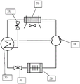
FIG. 1 is a schematic diagram of an exemplary heat transfer system that may be used for low and medium temperature refrigeration, and which includes a vapor injector.
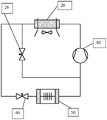
FIG. 2 is a schematic diagram of an exemplary heat transfer system that may be used for low and medium temperature refrigeration, and which includes a liquid ejector.
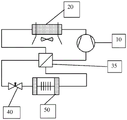
FIG. 3 is a schematic diagram of an exemplary heat transfer system that may be used for both low and moderate temperature refrigeration, and which includes a suction line/liquid line heat exchanger.
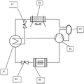
FIG. 4 is a schematic diagram of another exemplary heat transfer system that may be used for low and medium temperature refrigeration.
FIG. 5 is a schematic view of another exemplary heat transfer system that may be used for both low and moderate temperature refrigeration.
Detailed Description
Definition of:
For the purposes of the present invention, the term "about" with respect to amounts expressed as weight percentages means amounts in which the amounts of the components can vary by +/-2 weight%.
For the purposes of this invention, the term "about" with respect to temperature in degrees Celsius (C.) means that the temperature can vary by an amount of +/-5℃.
The term "capacity" is the amount of cooling (in BTUs per hour) provided by the refrigerant in the refrigeration system. This is determined experimentally by multiplying the change in enthalpy (in BTU/lb) of the refrigerant as it passes through the evaporator by the mass flow rate of the refrigerant. Enthalpy can be determined from measurements of the pressure and temperature of the refrigerant. The capacity of a refrigeration system relates to the ability to keep a zone cool to a particular temperature. The capacity of a refrigerant represents the amount of cooling or heating it provides and provides some measure of the compressor's ability to pump heat for a given volumetric flow of refrigerant. In other words, a refrigerant with a higher capacity will deliver more cooling or heating power given a particular compressor.
The phrase "coefficient of performance" (hereinafter "COP") is a generally accepted measure of refrigerant performance, and is particularly useful in expressing the relative thermodynamic efficiency of a refrigerant in a particular heating or cooling cycle involving evaporation or condensation of the refrigerant. In refrigeration engineering, the term denotes the ratio of available refrigeration or cooling capacity to the energy applied by the compressor in compressing a vapor, and thus the capacity of a given compressor to pump heat for a given volumetric flow of heat transfer fluid (such as a refrigerant). In other words, a refrigerant with a higher COP will deliver more cooling or heating power given a particular compressor. One method for estimating the COP of a refrigerant under specific operating conditions is from the thermodynamic properties of the refrigerant using standard refrigeration cycle analysis techniques (see, e.g., r.c. downing, fluor corpon REFRIGERANTS HANDBOOK, chapter 3, prentic-Hall, 1988, which is incorporated herein by reference in its entirety).
The phrase "discharge temperature" refers to the temperature of the refrigerant at the compressor outlet. The advantage of a low discharge temperature is that it allows the use of existing equipment without activating the thermal protection aspect of the system, which is preferably designed to protect the compressor components and avoid the use of expensive control measures (such as injection of liquid) to reduce the discharge temperature.
The phrase "global warming potential" (hereinafter "GWP") was established to allow comparison of the global warming effect of different gases. In particular, it is a measure of how much energy one ton of gas emitted will absorb in a given period of time relative to one ton of carbon dioxide emitted. The greater the GWP, the warmer the given gas will be in the earth over that time period as compared to CO 2. The time period typically used for GWP is 100 years. GWP provides a general metric-allowing analysts to accumulate estimates of emissions for different gases. See http:// www.protocolodemontreal.org.br/site/images/publications/servers _ manufature _ equalisation _ referagecaco _ radiocationado/com _ calcu _ el _ potential _ de _ calcium _ atomicity _ en _ las _ mecclas _ de _ referagesis
The term "occupational contact Limit (OEL)" is determined in accordance with ASHRAE Standard 34-2016 "nomenclature and Safety Classification of Refrigerants (signatures and Safety Classification of reflagers)".
As used herein, the term "alternative" means the composition of the present invention used in a heat transfer system designed for use with, or generally with, another refrigerant, or adapted for use with another refrigerant. By way of example, when the refrigerant or heat transfer composition of the present invention is used in a heat transfer system designed for use with R-404A, then the refrigerant or heat transfer composition of the present invention is an alternative to R-404A in such a system. Thus, it should be understood that the term "alternative" includes the refrigerant and heat transfer compositions of the present invention used in both new and existing systems designed for use with R-404A, typically R-404A, or suitable for use with R-404A.
The phrase "thermodynamic slip" applies to a zeotropic refrigerant mixture having a changing temperature during a phase change process in an evaporator or condenser at a constant pressure.
The term "cryogenic refrigeration system" refers to a heat transfer system operating at a condensing temperature of about 20 ℃ to about 60 ℃ and an evaporating temperature of about-45 ℃ up to and including-12 ℃.
The term "medium temperature refrigeration system" refers to a heat transfer system that operates at a condensing temperature of about 20 ℃ to about 60 ℃ and an evaporating temperature of-12 ℃ to about 0 ℃.
As used herein, the term "supermarket refrigeration" refers to a commercial refrigeration system for maintaining refrigerated or frozen food products in both product display cases and storage refrigerators.
As used herein, the term "transport refrigeration" refers to refrigeration systems used to transport refrigerated or frozen products by means of trucks, trailers, vans, intermodal containers, and cargo boxes. The term also includes the use of refrigeration and air conditioning on commercial, military and fishing vessels of greater than about 100 total tons (GT) (greater than about 24m in length).
Refrigerant and heat transfer compositions
Applicants have found that refrigerants of the present invention, including each of refrigerants 1 through 13 as described herein, can provide particularly advantageous properties, including: heat transfer characteristics; low or no toxicity; non-flammability; near zero ozone depletion potential ("ODP"); and lubricant compatibility, including miscibility with POE lubricants over the operating temperature and concentration ranges used in low and medium temperature refrigeration systems; and low GWP; particularly as a replacement for R-404A in low and medium temperature refrigeration systems including existing R-404A transport refrigeration systems, existing 404A commercial refrigeration systems, existing 404A supermarket refrigeration systems, existing 404A self-contained refrigeration systems, existing R-404A industrial refrigeration systems, existing R-404A plug-in vending machines, existing R-404A vapor injection refrigeration systems, and existing R-404A liquid injection refrigeration systems.
A particular advantage of the refrigerants of the present invention is that they are non-flammable when tested according to the non-flammability test defined herein. The skilled artisan will appreciate that flammability of the refrigerant is an important feature for certain important heat transfer applications. Accordingly, it would be desirable in the art to provide such a refrigerant composition: it is useful as an alternative to R-404A, which has excellent heat transfer characteristics, low or no toxicity, near zero ODP, and lubricant compatibility, including miscibility with POE lubricants over the operating temperature and concentration ranges used in low and medium temperature refrigeration systems, and which remains non-flammable in use. This desired advantage is met by the refrigerant of the present invention.
Applicants have found that the refrigerant compositions of the present invention are capable of achieving a combination of properties that are difficult to achieve, including a particularly low GWP. Thus, the compositions of the present invention have a GWP of less than 150, and preferably less than 100.
In addition, the refrigerant compositions of the present invention have a low ODP. Thus, the compositions of the present invention have an ODP of no greater than 0.05, preferably no greater than 0.02, and more preferably about zero.
In addition, the refrigerant compositions of the present invention show acceptable toxicity, and preferably have an OEL greater than about 400. As known to those skilled in the art, a non-flammable refrigerant having an OEL greater than about 400 is advantageous because it results in the refrigerant being classified as class a as desired in ASHRAE standard 34.
Applicants have found that heat transfer compositions of the present invention, including heat transfer compositions comprising each of refrigerants 1 through 13 as described herein, can provide particularly advantageous properties, including: heat transfer characteristics; chemical stability under conditions of use; low or no toxicity; non-flammability; near zero ozone depletion potential ("ODP"); and lubricant compatibility, including miscibility with POE lubricants over the operating temperature and concentration ranges used in low and medium temperature refrigeration systems; and low GWP; particularly as a replacement for R-404A in low and medium temperature refrigeration systems including existing R-404A transport refrigeration systems, existing 404A commercial refrigeration systems, existing 404A supermarket refrigeration systems, existing 404A self-contained refrigeration systems, existing R-404A industrial refrigeration systems, existing R-404A plug-in vending machines, existing R-404A vapor injection refrigeration systems, and existing R-404A liquid injection refrigeration systems.
The heat transfer composition can consist essentially of any refrigerant of the present invention, including each of refrigerants 1 through 13.
The heat transfer composition of the present invention can be comprised of any of the refrigerants of the present invention, including each of refrigerants 1 through 13.
The heat transfer compositions of the present invention may include other components to enhance or provide specific functions to these compositions. Such other components may include one or more of lubricants, dyes, solubilizers, compatibilizers, stabilizers, antioxidants, corrosion inhibitors, extreme pressure additives, and anti-wear additives.
Lubricant agent
The heat transfer compositions of the present invention specifically comprise a refrigerant (including each of refrigerants 1 through 13) and a lubricant as discussed herein. Applicants have found that heat transfer compositions of the present invention, including those comprising a lubricant (particularly a POE lubricant) and each of refrigerants 1 through 13 as described herein, are capable of providing particularly advantageous properties, including excellent refrigerant/lubricant compatibility, including miscibility with POE lubricant over the operating temperature and concentration ranges used in low and medium temperature refrigeration systems, including low and medium temperature transport refrigeration systems, commercial refrigeration systems, supermarket refrigeration systems, self-contained refrigeration systems, industrial refrigeration systems, and plug-in vending machines, in addition to the advantageous properties identified herein for refrigerants, particularly as a substitute for R-404A in low and medium temperature refrigeration systems.
Generally, the heat transfer compositions of the present invention comprising a lubricant comprise a lubricant, preferably in an amount of from about 0.1 wt.% to about 5 wt.%, or from 0.1 wt.% to about 1 wt.%, or from 0.1 wt.% to about 0.5 wt.%, based on the weight of the heat transfer composition.
Common refrigerant lubricants used in refrigeration machinery such as polyol esters (POE), polyalkylene glycols (PAG), silicone oils, mineral oils, Alkylbenzenes (AB), polyvinyl ethers (PVE), Polyethers (PE), and poly (alpha-olefins) (PAO) may be used in the refrigerant composition of the present invention.
Preferably, the lubricant is selected from POE, mineral oil, AB, PVE, and PE.
Preferably, the lubricant is POE.
Generally, the heat transfer compositions of the present invention comprising a POE lubricant comprise a POE lubricant, preferably in an amount of from about 0.1 wt.% to about 5 wt.%, or from 0.1 wt.% to about 1 wt.%, or from 0.1 wt.% to about 0.5 wt.%, based on the weight of the heat transfer composition.
Commercially available POEs that are preferred for use in the heat transfer compositions of the present invention include neopentyl glycol dipelargonate, which is available as Emery 2917 (registered trademark) and Hatcol 2370 (registered trademark), and pentaerythritol derivatives, including those sold by CPI Fluid Engineering under the tradenames Emkarate RL32-3MAF and Emkarate RL 68H. Emkarate RL32-3MAF and Emkarate RL68H are preferred POE lubricants with the properties identified below:

Commercially available polyvinyl ethers preferred for use in the heat transfer compositions of the present invention include those lubricants sold under the trade names FVC32D and FVC68D by Idemitsu (Idemitsu).
Commercially available mineral oils that are preferred for use in the heat transfer compositions of the present invention include Witco LP 250 (registered trademark) from Witco, from Winteridae, Suniso 3GS from Winteridae, and Calumet R015 from Calumet. Commercially available alkylbenzene lubricants include Zerol 150 (registered trademark) and Zerol available from Mobil Chemical industry (Shrieve Chemical)
A preferred heat transfer composition comprises refrigerant 1 and POE lubricant.
A preferred heat transfer composition comprises refrigerant 2 and POE lubricant.
A preferred heat transfer composition comprises refrigerant 3 and POE lubricant.
A preferred heat transfer composition comprises refrigerant 4 and POE lubricant.
A preferred heat transfer composition comprises refrigerant 5 and POE lubricant.
A preferred heat transfer composition comprises refrigerant 6 and POE lubricant.
A preferred heat transfer composition comprises refrigerant 7 and POE lubricant.
A preferred heat transfer composition comprises refrigerant 8 and POE lubricant.
A preferred heat transfer composition comprises refrigerant 9 and POE lubricant.
A preferred heat transfer composition comprises refrigerant 10 and POE lubricant.
A preferred heat transfer composition comprises refrigerant 11 and POE lubricant.
A preferred heat transfer composition comprises refrigerant 12 and a POE lubricant.
A preferred heat transfer composition comprises refrigerant 13 and POE lubricant.
A lubricant consisting essentially of POE having a viscosity of about 30 to about 70 at 40 ℃ as measured according to ASTM D445 is referred to herein as lubricant 1.
A preferred heat transfer composition comprises refrigerant 1 and lubricant 1.
A preferred heat transfer composition comprises refrigerant 2 and lubricant 1.
A preferred heat transfer composition comprises refrigerant 3 and lubricant 1.
A preferred heat transfer composition comprises refrigerant 4 and lubricant 1.
A preferred heat transfer composition comprises refrigerant 5 and lubricant 1.
A preferred heat transfer composition comprises refrigerant 6 and lubricant 1.
A preferred heat transfer composition comprises refrigerant 7 and lubricant 1.
A preferred heat transfer composition comprises refrigerant 8 and lubricant 1.
A preferred heat transfer composition comprises refrigerant 9 and lubricant 1.
A preferred heat transfer composition comprises a refrigerant 10 and a lubricant 1.
A preferred heat transfer composition comprises refrigerant 11 and lubricant 1.
A preferred heat transfer composition comprises refrigerant 12 and lubricant 1.
A preferred heat transfer composition comprises refrigerant 13 and lubricant 1.
A lubricant consisting essentially of POE having a viscosity of from about 30 to about 70 at 40 ℃ as measured according to ASTM D445 and present in an amount of from about 0.1% to about 1% based on the weight of the heat transfer composition is referred to herein as lubricant 2.
A preferred heat transfer composition comprises refrigerant 1 and lubricant 2.
A preferred heat transfer composition comprises refrigerant 2 and lubricant 2.
A preferred heat transfer composition comprises refrigerant 3 and lubricant 2.
The preferred heat transfer composition comprises refrigerant 4 and lubricant 2.
A preferred heat transfer composition comprises refrigerant 5 and lubricant 2.
A preferred heat transfer composition comprises refrigerant 6 and lubricant 2.
A preferred heat transfer composition comprises refrigerant 7 and lubricant 2.
A preferred heat transfer composition comprises refrigerant 8 and lubricant 2.
A preferred heat transfer composition comprises refrigerant 9 and lubricant 2.
A preferred heat transfer composition comprises refrigerant 10 and lubricant 2.
The preferred heat transfer composition comprises refrigerant 11 and lubricant 2.
The preferred heat transfer composition comprises refrigerant 12 and lubricant 2.
A preferred heat transfer composition comprises refrigerant 13 and lubricant 2.
Preferred heat transfer compositions comprise a refrigerant of the present invention (including each of refrigerants 1 through 13) and from about 0.1% to about 5%, or from about 0.1% to about 1%, or from about 0.1% to about 0.5% of a lubricant, wherein the percentages are based on the weight of lubricant in the heat transfer composition.
Preferred heat transfer compositions comprise a refrigerant of the present invention (including each of refrigerants 1 through 13) and from about 0.1% to about 5%, or from about 0.1% to about 1%, or from about 0.1% to about 0.5%, of a POE lubricant, wherein the percentages are based on the weight of lubricant in the heat transfer composition.
Preferred heat transfer compositions comprise a refrigerant of the present invention (including each of refrigerants 1 through 13) and from about 0.1% to about 5%, or from about 0.1% to about 1%, of lubricant 1, wherein the percentages are based on the weight of lubricant in the heat transfer composition.
A lubricant consisting essentially of POE having a viscosity of from about 30 to about 70 at 40 ℃ as measured according to ASTM D445 and present in an amount of from about 0.1% to about 0.5% based on the weight of the heat transfer composition is referred to herein as lubricant 3.
A lubricant consisting essentially of POE having a viscosity of from about 30 to about 70 at 40 ℃ as measured according to ASTM D445 and present in an amount of from about 0.1% to about 0.5% based on the weight of the heat transfer composition is referred to herein as lubricant 4.
Stabilizer:
The heat transfer compositions of the present invention specifically comprise a refrigerant (including each of refrigerants 1 through 13) and a stabilizer as discussed herein. Applicants have found that the heat transfer compositions of the present invention, including heat transfer compositions comprising a stabilizer and each of refrigerants 1 through 13 as described herein, are capable of providing particularly advantageous properties, which, in addition to the advantageous properties identified herein with respect to the refrigerant, also includes chemical stability over the operating temperature and concentration ranges used in low and medium temperature refrigeration systems, particularly as a replacement for R-404A in low and medium temperature refrigeration systems, the low and medium temperature refrigeration systems include existing R-404A transport refrigeration systems, existing 404A commercial refrigeration systems, existing 404A supermarket refrigeration systems, existing 404A self-contained refrigeration systems, existing R-404A industrial refrigeration systems, existing R-404A plug-in vending machines, existing R-404A vapor injection refrigeration systems, and existing R-404A liquid injection refrigeration systems.
In a preferred embodiment, the stabilizer comprises one or more of an alkylated naphthalene compound, a diene-based compound, a phenol-based compound, and isobutylene. Other compounds that may be used in the stabilizer include phosphorus-based compounds, nitrogen-based compounds, and epoxy compounds. Preferred compounds within each of these groups are described below.
Alkylated naphthalenes
Applicants have surprisingly and unexpectedly found that alkylated naphthalenes are highly effective as stabilizers for the heat transfer compositions of the present invention. As used herein, the term "alkylated naphthalene" refers to a compound having the structure:

wherein R is 1 To R 8 Each independently selected from the group consisting of a straight chain alkyl group, a branched alkyl group, and hydrogen. The specific length of the alkyl chain and mixtures of branched and straight chains with hydrogen can vary within the scope of the present invention, and those skilled in the art will recognize and appreciate that such variations reflect the physical characteristics of the alkylated naphthalene, including in particular the viscosity of the alkylated compound, and that manufacturers of such materials typically define the material by reference to one or more of such characteristics as an alternative specification for a particular R group.
Applicants have found that unexpected, surprising and advantageous results are associated with the use of alkylated naphthalenes according to the present invention as stabilizers, and for convenience, alkylated naphthalene compounds having the following characteristics are referred to herein as alkylated naphthalenes 1 through alkylated naphthalene 5, as shown in row 1 through row 5, respectively, of the alkylated naphthalene characteristics of table 1 below:
Characterization of alkylated naphthalenes Table 1

As used herein, the term "about" means +/-4cSt, in combination with a viscosity at 40 ℃ measured according to ASTM D445.
As used herein, the term "about" means +/-0.4cSt, in conjunction with viscosity at 100 ℃ as measured according to ASTM D445.
As used herein, the term "about" means +/-5 ℃ in conjunction with a pour point measured according to ASTM D97.
Applicants have also found that unexpected, surprising and advantageous results are associated with the use of alkylated naphthalenes according to the present invention as stabilizers, and for convenience, alkylated naphthalene compounds having the following characteristics are referred to herein as alkylated naphthalenes 6 through alkylated naphthalene 10, as shown in rows 6 through 10, respectively, of the alkylated naphthalene characteristics of table 2 below:
characterization of alkylated naphthalenes Table 2


Examples of alkylated naphthalenes within the meaning of alkylated naphthalene 1 through alkylated naphthalene 6 include those sold by King Industries under the following tradenames: NA-LUBE KR-007A; KR-008, KR-009; KR-015; KR-019; KR-005 FG; KR-015 FG; and KR-029 FG.
Examples of alkylated naphthalenes within the meaning of alkylated naphthalene 2 and alkylated naphthalene 7 include those sold by the King industries under the following tradenames: NA-LUBE KR-007A; KR-008, KR-009; and KR-005 FG.
Examples of alkylated naphthalenes within the meaning of alkylated naphthalene 5 and alkylated naphthalene 10 include the product sold by King industries under the name NA-LUBE KR-008.
Alkylated naphthalenes are preferably in the heat transfer compositions of the invention comprising the refrigerants of the invention (including each of refrigerants 1 through 13), where the alkylated naphthalene is present in an amount of 0.01% to about 10%, or about 1.5% to about 4.5%, or about 2.5% to about 3.5%, where these amounts are weight percentages based on the amount of alkylated naphthalene plus refrigerant.
Diene-based compound
The diene-based compound may include a C3 to C15 diene and to any compound formed by the reaction of two or more C3 to C4 dienes. Preferably, the diene-based compound is selected from allyl ethers, propadiene, butadiene, isoprene, and terpenes. The diene-based compound is preferably a terpene including, but not limited to, rutinene, retinal, geraniol, terpinene, delta 3-carene, terpinolene, phellandrene, fenchenene, myrcene, farnesene, pinene, nerol, citral, camphor, menthol, limonene, nerolidol, phytol, carnosic acid, and vitamin a 1. Preferably, the stabilizing agent is farnesene. Preferred terpene stabilizers are disclosed in U.S. provisional patent application 60/638,003, filed on 12.12.2004 as published in US2006/0167044a1, which is incorporated herein by reference. Further, the diene-based compound can be provided in the heat transfer composition in an amount of greater than 0 wt% and preferably from 0.0001 wt% to about 5 wt%, preferably from 0.001 wt% to about 2.5 wt%, and more preferably from 0.01 wt% to about 1 wt%. In each case, weight percent refers to the weight of the refrigerant plus one or more diene-based compounds in the heat transfer composition.
Phenol-based compounds
The phenol-based compound may be one or more compounds selected from the group consisting of: 4, 4' -methylenebis (2, 6-di-tert-butylphenol); 4, 4' -bis (2, 6-di-tert-butylphenol); 2, 2-or 4, 4-biphenyldiols including 4, 4' -bis (2-methyl-6-tert-butylphenol); derivatives of 2, 2-or 4, 4-biphenyldiol; 2, 2' -methylenebis (4-ethyl-6-tert-butylphenol); 2, 2' -methylenebis (4-methyl-6-tert-butylphenol); 4, 4-butylidenebis (3-methyl-6-tert-butylphenol); 4, 4-isopropylidenebis (2, 6-di-tert-butylphenol); 2, 2' -methylenebis (4-methyl-6-nonylphenol); 2, 2' -isobutylidene bis (4, 6-dimethylphenol); 2, 2' -methylenebis (4-methyl-6-cyclohexylphenol); 2, 6-di-tert-butyl-4-methylphenol (BHT); 2, 6-di-tert-butyl-4-ethylphenol: 2, 4-dimethyl-6-tert-butylphenol; 2, 6-di-tert-alpha-dimethylamino-p-cresol; 2, 6-di-tert-butyl-4 (N, N' -dimethylaminomethylphenol); 4, 4' -thiobis (2-methyl-6-tert-butylphenol); 4, 4' -thiobis (3-methyl-6-tert-butylphenol); 2, 2' -thiobis (4-methyl-6-tert-butylphenol); bis (3-methyl-4-hydroxy-5-tert-butylbenzyl) sulfide; bis (3, 5-di-tert-butyl-4-hydroxybenzyl) sulfide, tocopherol, hydroquinone, 2 ', 6, 6 ' -tetra-tert-butyl-4, 4 ' -methylenediphenol and tert-butylhydroquinone, and preferably BHT.
The phenolic compound can be provided in the heat transfer composition in an amount of greater than 0 wt% and preferably from 0.0001 wt% to about 5 wt%, preferably from 0.001 wt% to about 2.5 wt%, and more preferably from 0.01 wt% to about 1 wt%. In each case, weight percent refers to the weight of the one or more phenol-based compounds plus refrigerant in the heat transfer composition.
Phosphorus-based compounds
The phosphorus compound may be a phosphite or phosphate compound. For the purposes of the present invention, the phosphite compounds may be diaryl, dialkyl, triaryl and/or trialkyl phosphites, and/or mixed aryl/alkyl di-or tri-substituted phosphites, in particular selected from one or more of the following compounds: hindered phosphites, tri- (di-tert-butylphenyl) phosphite, di-n-octyl phosphite, isooctyldiphenyl phosphite, isodecyldiphenylphosphite, triisodecyldiphenylphosphate, triphenyl phosphite and diphenyl phosphite, especially diphenyl phosphite. The phosphate compound may be a triaryl phosphate, a trialkyl phosphate, an alkyl phosphate of mono acid (alkyl mono acid phosphate), an aryl phosphate of di acid (aryl di acid phosphate), an amine phosphate, preferably a triaryl phosphate and/or a trialkyl phosphate, especially tri-n-butyl phosphate.
The phosphorus compound can be provided in the heat transfer composition in an amount greater than 0 wt% and preferably from 0.0001 wt% to about 5 wt%, preferably from 0.001 wt% to about 2.5 wt%, and more preferably from 0.01 wt% to about 1 wt%. By weight in each case is meant the weight of the one or more phosphorus-based compounds plus refrigerant in the heat transfer composition.
Nitrogen compound
When the stabilizer comprises a nitrogen compound, the stabilizer may comprise an amine-based compound, such as one or more secondary or tertiary amines selected from: diphenylamine, p-phenylenediamine, triethylamine, tributylamine, diisopropylamine, triisopropylamine and tributylamineIsobutylamine. The amine based compound may be an amine antioxidant such as a substituted piperidine compound, i.e. a derivative of an alkyl substituted piperidinyl (piperidyl), piperazinone or alkoxypiperidinyl, in particular one or more amine antioxidants selected from: 2, 2, 6, 6-tetramethyl-4-piperidone, 2, 6, 6-tetramethyl-4-piperidinol; bis (1, 2, 2, 6, 6-pentamethylpiperidyl) sebacate; bis (2, 2, 6, 6-tetramethyl-4-piperidyl) sebacate, poly (N-hydroxyethyl-2, 2, 6, 6-tetramethyl-4-hydroxy-piperidyl succinate), alkylated p-phenylenediamines, such as N-phenyl-N '- (1, 3-dimethyl-butyl) -p-phenylenediamine or N, N' -di-sec-butyl-p-phenylenediamine, and hydroxylamines, such as tallow amine, methylbistallow amine and bistallow amine, or phenol-alpha-naphthylamine or  765(Ciba)、
 1944(Mayzo Inc) and
 1770(Mayzo Inc). For the purposes of the present invention, the amine-based compound may also be one or more of an alkyl diphenylamine such as bis (nonyl aniline), a dialkylamine such as (N- (1-methylethyl) -2-propylamine, or phenyl- α -naphthylamine (PANA), alkyl-phenyl- α -naphthyl-amine (APANA), and bis (nonylphenyl) amine.
Alternatively, or in addition to the nitrogen compounds specified above, one or more compounds selected from dinitrobenzene, nitrobenzene, nitromethane, nitrosobenzene, and TEMPO [ (2, 2, 6, 6-tetramethylpiperidin-1-yl) oxy ] may be used as the stabilizer.
The nitrogen compound can be provided in the heat transfer composition in an amount of greater than 0 wt.% and from 0.0001 wt.% to about 5 wt.%, preferably from 0.001 wt.% to about 2.5 wt.%, and more preferably from 0.01 wt.% to about 1 wt.%. In each case, weight percent refers to the weight of the refrigerant plus one or more nitrogen-based compounds in the heat transfer composition.
Isobutene
Isobutylene can be provided in the heat transfer composition in an amount greater than 0 wt.% and from 0.0001 wt.% to about 5 wt.%, preferably from 0.001 wt.% to about 2.5 wt.%, and more preferably from 0.01 wt.% to about 1 wt.%. In each case, weight percent refers to the weight of isobutylene plus refrigerant in the heat transfer composition.
Epoxides and the like
Useful epoxides include aromatic epoxides, alkyl epoxides, and alkenyl epoxides.
Combination of stabilizers
Preferably, the heat transfer composition comprises a refrigerant of the present invention (including each of refrigerants 1 through 13) and a stabilizer composition comprising a diene-based compound and an alkylated naphthalene. The stabilizer as described in this paragraph is referred to herein as stabilizer 1.
The heat transfer composition of the present invention may preferably comprise a refrigerant 1 and a stabilizer 1.
The heat transfer composition of the present invention may preferably comprise a refrigerant 2 and a stabilizer 1.
The heat transfer composition of the present invention may preferably comprise a refrigerant 3 and a stabilizer 1.
The heat transfer composition of the present invention may preferably comprise a refrigerant 4 and a stabilizer 1.
The heat transfer composition of the present invention may preferably comprise a refrigerant 5 and a stabilizer 1.
The heat transfer composition of the present invention may preferably comprise a refrigerant 6 and a stabilizer 1.
The heat transfer composition of the present invention may preferably comprise a refrigerant 7 and a stabilizer 1.
The heat transfer composition of the present invention may preferably comprise a refrigerant 8 and a stabilizer 1.
The heat transfer composition of the present invention may preferably comprise a refrigerant 9 and a stabilizer 1.
The heat transfer composition of the present invention may preferably comprise a refrigerant 10 and a stabilizer 1.
The heat transfer composition of the present invention may preferably comprise a refrigerant 11 and a stabilizer 1.
The heat transfer composition of the present invention may preferably comprise a refrigerant 12 and a stabilizer 1.
The heat transfer composition of the present invention may preferably comprise a refrigerant 13 and a stabilizer 1.
Preferably, the heat transfer composition comprises a refrigerant of the present invention (including each of refrigerants 1 through 13) and a stabilizer composition comprising a diene-based compound, an alkylated naphthalene selected from alkylated naphthalene 1, and a phenol-based compound. The stabilizer as described in this paragraph is referred to herein as stabilizer 2.
The heat transfer composition of the present invention may preferably comprise a refrigerant 1 and a stabilizer 2.
The heat transfer composition of the present invention may preferably comprise a refrigerant 2 and a stabilizer 2.
The heat transfer composition of the present invention may preferably comprise a refrigerant 3 and a stabilizer 2.
The heat transfer composition of the present invention may preferably comprise a refrigerant 4 and a stabilizer 2.
The heat transfer composition of the present invention may preferably comprise a refrigerant 5 and a stabilizer 2.
The heat transfer composition of the present invention may preferably comprise a refrigerant 6 and a stabilizer 2.
The heat transfer composition of the present invention may preferably comprise a refrigerant 7 and a stabilizer 2.
The heat transfer composition of the present invention may preferably comprise a refrigerant 8 and a stabilizer 2.
The heat transfer composition of the present invention may preferably comprise a refrigerant 9 and a stabilizer 2.
The heat transfer composition of the present invention may preferably comprise a refrigerant 10 and a stabilizer 2.
The heat transfer composition of the present invention may preferably comprise a refrigerant 11 and a stabilizer 2.
The heat transfer composition of the present invention may preferably comprise a refrigerant 12 and a stabilizer 2.
The heat transfer composition of the present invention may preferably comprise a refrigerant 13 and a stabilizer 2.
Preferably, the heat transfer composition comprises a refrigerant of the present invention (including each of refrigerants 1 through 13) and a stabilizer composition comprising farnesene, and alkylated naphthalene 4 and BHT. The stabilizer as described in this paragraph is referred to herein as stabilizer 3.
The heat transfer composition of the present invention may preferably comprise a refrigerant 1 and a stabilizer 3.
The heat transfer composition of the present invention may preferably comprise a refrigerant 2 and a stabilizer 3.
The heat transfer composition of the present invention may preferably comprise a refrigerant 3 and a stabilizer 3.
The heat transfer composition of the present invention may preferably comprise a refrigerant 4 and a stabilizer 3.
The heat transfer composition of the present invention may preferably comprise a refrigerant 5 and a stabilizer 3.
The heat transfer composition of the present invention may preferably comprise a refrigerant 6 and a stabilizer 3.
The heat transfer composition of the present invention may preferably comprise a refrigerant 7 and a stabilizer 3.
The heat transfer composition of the present invention may preferably comprise a refrigerant 8 and a stabilizer 3.
The heat transfer composition of the present invention may preferably comprise a refrigerant 9 and a stabilizer 3.
The heat transfer composition of the present invention may preferably comprise a refrigerant 10 and a stabilizer 3.
The heat transfer composition of the present invention may preferably comprise a refrigerant 11 and a stabilizer 3.
The heat transfer composition of the present invention may preferably comprise a refrigerant 12 and a stabilizer 3.
The heat transfer composition of the present invention may preferably comprise a refrigerant 13 and a stabilizer 3.
The heat transfer composition may comprise a refrigerant of the present invention (including each of refrigerants 1 through 13) and a stabilizer composition comprising farnesene, and an alkylated naphthalene selected from alkylated naphthalene 1 and BHT. The stabilizer as described in this paragraph is referred to herein as stabilizer 4.
The heat transfer composition can comprise a refrigerant of the present invention (including each of refrigerants 1 through 13), and a stabilizer composition consisting essentially of farnesene, alkylated naphthalene 5 and BHT. The stabilizer as described in this paragraph is referred to herein as stabilizer 5.
The heat transfer composition may comprise a refrigerant of the present invention (including each of refrigerants 1 through 13), and a stabilizer composition consisting of farnesene, alkylated naphthalene 5 and BHT. The stabilizer as described in this paragraph is referred to herein as stabilizer 6.
The heat transfer composition may comprise a refrigerant of the present invention (including each of refrigerants 1 through 13) and a stabilizer composition comprising isobutylene and an alkylated naphthalene selected from alkylated naphthalene 1. The stabilizer as described in this paragraph is referred to herein as stabilizer 7.
The heat transfer composition can comprise a refrigerant of the present invention (including each of refrigerants 1 through 13) and a stabilizer composition comprising isobutylene, alkylated naphthalene 5, and BHT. The stabilizer as described in this paragraph is referred to herein as stabilizer 8.
The heat transfer composition can comprise a refrigerant of the present invention (including each of refrigerants 1 through 13), and a stabilizer composition consisting essentially of isobutylene, alkylated naphthalene 5, and BHT. The stabilizer as described in this paragraph is referred to herein as stabilizer 9.
The heat transfer composition can comprise a refrigerant of the present invention (including each of refrigerants 1 through 13), and a stabilizer composition consisting of isobutylene, alkylated naphthalene 5, and BHT. The stabilizer as described in this paragraph is referred to herein as stabilizer 10.
The heat transfer compositions of the present invention may comprise a refrigerant of the present invention (including each of refrigerants 1 through 13) and a stabilizer composition comprising alkylated naphthalene 4, wherein the alkylated naphthalene is present in an amount of from 0.0001 wt.% to about 5 wt.%, based on the weight of the heat transfer composition. The stabilizer within the specified amount in the heat transfer composition as described in this paragraph is referred to herein as stabilizer 11.
The heat transfer compositions of the present invention may preferably comprise a refrigerant of the present invention (including each of refrigerants 1 through 13) and a stabilizer composition comprising alkylated naphthalene 5, wherein the alkylated naphthalene is present in an amount of from 0.0001 wt.% to about 5 wt.%, based on the weight of the heat transfer composition. The stabilizing agent within the specified amount in the heat transfer composition as described in this paragraph is referred to herein as stabilizing agent 12.
The heat transfer compositions of the present invention may preferably comprise a refrigerant of the present invention (including each of refrigerants 1 through 13) and a stabilizer composition comprising BHT, wherein the BHT is present in an amount of from about 0.0001 wt.% to about 5 wt.% based on the weight of the heat transfer composition. The stabilizer within the specified amount in the heat transfer composition as described in this paragraph is referred to herein as stabilizer 13.
The heat transfer compositions of the present invention may preferably comprise a refrigerant of the present invention (including each of refrigerants 1 through 13) and a stabilizer composition comprising farnesene, alkylated naphthalene 4 and BHT, wherein farnesene is provided in an amount from about 0.0001% to about 5% by weight, alkylated naphthalene 4 is provided in an amount from about 0.0001% to about 10% by weight, and BHT is provided in an amount from about 0.0001% to about 5% by weight, wherein the percentages are based on the weight of the heat transfer composition. The stabilizer within the specified amount in the heat transfer composition as described in this paragraph is referred to herein as stabilizer 14.
The heat transfer compositions of the present invention can comprise a refrigerant of the present invention (including each of refrigerants 1 through 13) and a stabilizer composition comprising farnesene, alkylated naphthalene 4 and BHT, wherein farnesene is provided in an amount from 0.001 wt.% to about 2.5 wt.%, alkylated naphthalene 4 is provided in an amount from 0.001 wt.% to about 10 wt.%, and BHT is provided in an amount from 0.001 wt.% to about 2.5 wt.%, wherein the percentages are based on the weight of the heat transfer composition. The stabilizer within the specified amount in the heat transfer composition as described in this paragraph is referred to herein as stabilizer 15.
The heat transfer compositions of the present invention may more preferably comprise any of the refrigerants of the present invention (including each of refrigerants 1 through 13) and a stabilizer composition comprising farnesene, alkylated naphthalene 4 and BHT, wherein farnesene is provided in an amount from 0.001 wt.% to about 2.5 wt.%, alkylated naphthalene 4 is provided in an amount from 1.5 wt.% to about 4.5 wt.%, and BHT is provided in an amount from 0.001 wt.% to about 2.5 wt.%, wherein the percentages are based on the weight of the heat transfer composition. The stabilizer within the specified amount in the heat transfer composition as described in this paragraph is referred to herein as stabilizer 16.
The heat transfer compositions of the present invention may more preferably comprise any of the refrigerants of the present invention (including each of refrigerants 1 through 13) and a stabilizer composition comprising farnesene, alkylated naphthalene 5 and BHT, wherein farnesene is provided in an amount of from 0.001 wt.% to about 2.5 wt.%, alkylated naphthalene 5 is provided in an amount of from 2.5 wt.% to 3.5 wt.%, and BHT is provided in an amount of from 0.001 wt.% to about 2.5 wt.%, wherein the percentages are based on the weight of the heat transfer composition. The stabilizer within the specified amount in the heat transfer composition as described in this paragraph is referred to herein as stabilizer 17.
Heat transfer compositions comprising a refrigerant, a lubricant, and a stabilizer
The heat transfer composition of the present invention can comprise any refrigerant of the present invention (including each of refrigerants 1 through 13), as well as any lubricant of the present invention (including each of lubricants 1 through 3) and stabilizer of the present invention (including each of stabilizers 1 through 17).
The heat transfer composition of the present invention can comprise any of the refrigerants of the present invention (including each of refrigerants 1 through 13), a POE lubricant, and stabilizer 1.
The heat transfer composition of the present invention may comprise any of the refrigerants of the present invention (including each of refrigerants 1 through 13), lubricant 1, and stabilizer 1.
The heat transfer composition of the present invention may comprise any of the refrigerants of the present invention (including each of refrigerants 1 through 13), lubricant 2, and stabilizer 1.
The heat transfer composition of the present invention can comprise any of the refrigerants of the present invention (including each of refrigerants 1 through 13), a lubricant 3, and a stabilizer 1.
The heat transfer composition of the present invention can comprise any of the refrigerants of the present invention (including each of refrigerants 1 through 13), a POE lubricant, and stabilizer 2.
The heat transfer composition of the present invention can comprise any of the refrigerants of the present invention (including each of refrigerants 1 through 13), lubricant 1, and stabilizer 2.
The heat transfer composition of the present invention may comprise any of the refrigerants of the present invention (including each of refrigerants 1 through 13), lubricant 2, and stabilizer 2.
The heat transfer composition of the present invention can comprise any of the refrigerants of the present invention (including each of refrigerants 1 through 13), a lubricant 3, and a stabilizer 2.
The heat transfer composition of the present invention can comprise any of the refrigerants of the present invention (including each of refrigerants 1 through 13), a POE lubricant, and stabilizer 3.
The heat transfer composition of the present invention can comprise any of the refrigerants of the present invention (including each of refrigerants 1 through 13), lubricant 1, and stabilizer 3.
The heat transfer composition of the present invention can comprise any of the refrigerants of the present invention (including each of refrigerants 1 through 13), lubricant 2, and stabilizer 3.
The heat transfer composition of the present invention may comprise any of the refrigerants of the present invention (including each of refrigerants 1 through 13), lubricant 3, and stabilizer 3.
The heat transfer composition of the present invention may comprise any of the refrigerants of the present invention, including each of refrigerants 1 through 13, as well as lubricant 1 and stabilizer 14.
The heat transfer composition of the present invention may comprise any refrigerant of the present invention (including each of refrigerants 1 through 13), lubricant 1, and stabilizer 14.
The heat transfer composition of the present invention may comprise any of the refrigerants of the present invention (including each of refrigerants 1 through 13), lubricant 2, and stabilizer 14.
The heat transfer composition of the present invention may comprise any of the refrigerants of the present invention (including each of refrigerants 1 through 13), lubricant 3, and stabilizer 14.
The heat transfer composition of the present invention may comprise a refrigerant 1, a stabilizer 1, and a lubricant 1.
The heat transfer composition of the present invention may comprise a refrigerant 2, a stabilizer 1, and a lubricant 1.
The heat transfer composition of the present invention may comprise a refrigerant 3, a stabilizer 1, and a lubricant 1.
The heat transfer composition of the present invention may comprise a refrigerant 4, a stabilizer 1, and a lubricant 1.
The heat transfer composition of the present invention may comprise a refrigerant 5, a stabilizer 1, and a lubricant 1.
The heat transfer composition of the present invention may comprise a refrigerant 6, a stabilizer 1, and a lubricant 1.
The heat transfer composition of the present invention may comprise a refrigerant 7, a stabilizer 1, and a lubricant 1.
The heat transfer composition of the present invention may comprise a refrigerant 8, a stabilizer 1, and a lubricant 1.
The heat transfer composition of the present invention may comprise a refrigerant 9, a stabilizer 1, and a lubricant 1.
The heat transfer composition of the present invention may comprise a refrigerant 10, a stabilizer 1, and a lubricant 1.
The heat transfer composition of the present invention may comprise a refrigerant 11, a stabilizer 1, and a lubricant 1.
The heat transfer composition of the present invention may comprise a refrigerant 12, a stabilizer 1, and a lubricant 1.
The heat transfer composition of the present invention may comprise a refrigerant 13, a stabilizer 1, and a lubricant 1. The heat transfer composition of the present invention may comprise refrigerant 1, POE lubricant, and a stabilizer selected from the group consisting of stabilizer 1, stabilizer 2, stabilizer 3, stabilizer 7, and stabilizer 14.
The heat transfer composition of the present invention may comprise refrigerant 1, lubricant 1, and a stabilizer selected from the group consisting of stabilizer 1, stabilizer 2, stabilizer 3, stabilizer 7, and stabilizer 14.
The heat transfer composition of the present invention may comprise a refrigerant 1, a lubricant 2, and a stabilizer selected from the group consisting of stabilizer 1, stabilizer 2, stabilizer 3, stabilizer 7, and stabilizer 14.
The heat transfer composition of the present invention may comprise refrigerant 4, POE lubricant, and a stabilizer selected from the group consisting of stabilizer 1, stabilizer 2, stabilizer 3, stabilizer 7, and stabilizer 14.
The heat transfer composition of the present invention may comprise a refrigerant 4, a lubricant 1, and a stabilizer selected from the group consisting of stabilizer 1, stabilizer 2, stabilizer 3, stabilizer 7, and stabilizer 14.
The heat transfer composition of the present invention may comprise a refrigerant 4, a lubricant 2, and a stabilizer selected from the group consisting of stabilizer 1, stabilizer 2, stabilizer 3, stabilizer 7, and stabilizer 14.
The heat transfer composition of the present invention may comprise refrigerant 8, a POE lubricant, and a stabilizer selected from the group consisting of stabilizer 1, stabilizer 2, stabilizer 3, stabilizer 7, and stabilizer 14.
The heat transfer composition of the present invention may comprise a refrigerant 8, a lubricant 1, and a stabilizer selected from the group consisting of stabilizer 1, stabilizer 2, stabilizer 3, stabilizer 7, and stabilizer 14.
The heat transfer composition of the present invention may comprise a refrigerant 8, a lubricant 2, and a stabilizer selected from the group consisting of stabilizer 1, stabilizer 2, stabilizer 3, stabilizer 7, and stabilizer 14.
Those skilled in the art, having reference to the teachings contained herein, may also include other additives not mentioned herein without departing from the novel and essential characteristics of the present invention.
Combinations of surfactants and solubilizers may also be added to the compositions of the present invention to aid in oil solubility, as disclosed in U.S. Pat. No. 6,516,837, the disclosure of which is incorporated by reference in its entirety.
Method, use and system
Refrigerant and heat transfer compositions as disclosed herein are provided for use in heat transfer applications, including cryogenic refrigeration systems, including cryogenic commercial refrigeration systems (including cryogenic supermarket refrigeration systems) and cryogenic transport systems.
Refrigerant and heat transfer compositions as disclosed herein are provided for use in medium temperature refrigeration systems, including medium temperature commercial refrigeration systems (including medium temperature supermarket refrigeration systems and medium temperature transport systems).
The compositions of the present invention are useful in systems suitable for use with R-404 refrigerants, such as new heat transfer systems.
Any reference to the heat transfer compositions of the present invention refers to each and any of the heat transfer compositions as described herein. Thus, for the following discussion of the use or application of the compositions of the present invention, the heat transfer composition may comprise, consist essentially of, or consist of any of the refrigerants described herein in combination with the stabilizers and lubricants discussed herein, including: (i) each of the refrigerants 1 to 13; (ii) any combination of each of the refrigerants 1 to 13 and each of the stabilizers 1 to 19; (iii) any combination of each of refrigerants 1 through 13 and any lubricant (including POE lubricant and lubricants 1 through 2); and (iv) and any combination of each of refrigerants 1 through 13 and each of stabilizers 1 through 19 and any lubricant (including POE lubricant and lubricants 1 through 2).
For heat transfer systems of the present invention that include a compressor and a lubricant for the compressor in the system, the system may contain a load of refrigerant and lubricant such that the lubricant load in the system is from about 5 wt.% to 60 wt.%, or from about 10 wt.% to about 60 wt.%, or from about 20 wt.% to about 50 wt.%, or from about 20 wt.% to about 40 wt.%, or from about 20 wt.% to about 30 wt.%, or from about 30 wt.% to about 50 wt.%, or from about 30 wt.% to about 40 wt.%. As used herein, the term "lubricant loading" refers to the total weight of lubricant included in a system as a percentage of the total amount of lubricant and refrigerant included in the system. Such systems may also include a lubricant loading of about 5 wt.% to about 10 wt.%, or about 8 wt.% of the heat transfer composition.
The present invention provides a heat transfer system comprising a refrigerant of the present invention (including each of refrigerants 1 through 13), a lubricant of the present invention, and alkylated naphthalene present in an amount of from 0.1% to about 20%, or from about 5% to about 15%, or from about 8% to about 12%, wherein these amounts are weight percentages based on the amount of alkylated naphthalene plus lubricant in the system.
The present invention provides a heat transfer system comprising a refrigerant of the present invention (including each of refrigerants 1 through 13), lubricant 1, and alkylated naphthalene in an amount of 0.1% to about 20%, or about 5% to about 15%, or about 8% to about 12%, wherein these amounts are weight percentages based on the amount of alkylated naphthalene plus lubricant in the system.
The present invention provides a heat transfer system comprising a refrigerant of the present invention (including each of refrigerants 1 through 13), lubricant 2, and alkylated naphthalene in an amount of 0.1% to about 20%, or about 5% to about 15%, or about 8% to about 12%, wherein these amounts are weight percentages based on the amount of alkylated naphthalene plus lubricant in the system.
Exemplary Heat transfer systems
As described in detail below, the preferred system of the present invention comprises a compressor, a condenser, an expansion device, and an evaporator, all of which are connected in fluid communication using piping, valving, and a control system such that the refrigerant and the relevant components of the heat transfer composition can flow through the system in a known manner to complete the refrigeration cycle. An exemplary schematic of such a basic system is shown in fig. 1. Specifically, the system schematically illustrated in fig. 1 shows a compressor 10 providing compressed refrigerant vapor to a condenser 20. The compressed refrigerant vapor is condensed to produce liquid refrigerant, which is then directed to an expansion device 40 that produces refrigerant at a reduced temperature and pressure, which is then provided to an evaporator 50. In the evaporator 50, liquid refrigerant absorbs heat from the body or fluid being cooled, thereby producing refrigerant vapor, which is then provided to the suction line of the compressor.
The refrigeration system shown in fig. 2 is the same as that described above in connection with fig. 1, except that it includes a vapor injection system including a heat exchanger 30 and a bypass expansion valve 25. The bypass expansion device 25 diverts a portion of the refrigerant flow at the condenser outlet through the device to provide liquid refrigerant to the heat exchanger 30 at reduced pressure and thus to provide liquid refrigerant to the heat exchanger 30 at a lower temperature. The relatively cool liquid refrigerant then exchanges heat with the remaining relatively high temperature liquid from the condenser. This operation produces a subcooled liquid to the main expansion device 40 and evaporator 50 and returns a relatively cool refrigerant vapor to the compressor 10. In this manner, injection of cooled refrigerant vapor to the suction side of the compressor serves to maintain the compressor discharge temperature within acceptable limits, which may be particularly advantageous in cryogenic systems utilizing high compression ratios.
The refrigeration system shown in fig. 3 is the same as that described above in connection with fig. 1, except that it includes a liquid injection system that includes a bypass valve 26. Bypass valve 26 diverts a portion of the liquid refrigerant exiting the condenser to the compressor, preferably to the liquid injection port of compressor 10. In this manner, liquid refrigerant is injected to the suction side of the compressor for maintaining the compressor discharge temperature within acceptable limits, which may be particularly advantageous in cryogenic systems utilizing high compression ratios.
The refrigeration system shown in fig. 4 is the same as that described above in connection with fig. 1, except that it includes a liquid-line/suction-line heat exchanger 35. Valve 25 diverts a portion of the refrigerant flow at the condenser outlet to a liquid-line/suction-line heat exchanger where heat is transferred from the liquid refrigerant to the refrigerant vapor exiting evaporator 50.
The refrigeration system shown in fig. 5 is the same as that described above in connection with fig. 1, except that it includes an oil separator 60 connected to the outlet of the compressor 10. As is known to those skilled in the art, a quantity of compressor lubricant will typically be carried into the compressor discharge refrigerant vapor, and an oil separator is included to provide a means of separating the lubricant liquid from the refrigerant vapor, and the resulting refrigerant vapor of reduced lubricant oil content travels to the condenser inlet, and the liquid lubricant is then returned to a lubricant reservoir for lubricating the compressor, such as a lubricant receiver. In preferred embodiments, the oil separator comprises a chelating material as described herein, preferably in the form of a filter or solid core.
Those skilled in the art will appreciate that the different device/configuration options shown in fig. 2-5, each separately, may be combined and used together, which is deemed advantageous for any particular application.
System with chelating material
The heat transfer system according to the present invention may comprise a compressor, an evaporator, a condenser and an expansion device (in communication with each other), a refrigerant of the present invention (including any of the refrigerants 1 to 13), a lubricant (including POE lubricant and lubricants 1 to 2), and a chelating material in the system, wherein the chelating material preferably comprises:
i. copper or copper alloy, or
Activated alumina, or
A zeolite molecular sieve containing copper, silver, lead, or combinations thereof, or
An anion exchange resin, or
A dehumidifying material, preferably a dehumidifying molecular sieve, or
A combination of two or more of the foregoing.
Preferred materials from each of the above categories (i) - (v) are described below.
a. Copper/copper alloy chelate material
The chelating material may be copper or a copper alloy, preferably copper. In addition to copper, the copper alloy may also contain one or more other metals, such as tin, aluminum, silicon, nickel, or combinations thereof. Alternatively or additionally, the copper alloy may comprise one or more non-metallic elements, such as carbon, nitrogen, silicon, oxygen, or combinations thereof.
It should be understood that the copper alloy may contain varying amounts of copper. For example, the copper alloy may comprise at least about 5 wt.%, at least about 15 wt.%, at least about 30 wt.%, at least about 50 wt.%, at least about 70 wt.%, or at least about 90 wt.% copper, based on the total weight of the copper alloy. It is also understood that the copper alloy may comprise from about 5 wt.% to about 95 wt.%, from about 10 wt.% to about 90 wt.%, from about 15 wt.% to about 85 wt.%, from about 20 wt.% to about 80 wt.%, from about 30 wt.% to about 70 wt.%, or from about 40 wt.% to about 60 wt.% copper, based on the total weight of the copper alloy.
Alternatively, copper may be used as the chelating material. Copper metal can contain impurity levels of other elements or compounds. For example, the copper metal can contain at least about 99 wt.%, more preferably at least about 99.5 wt.%, more preferably at least about 99.9 wt.% elemental copper.
The copper or copper alloy may be in any form that allows the refrigerant to contact the surface of the copper or copper alloy. Preferably, the form of the copper or copper alloy is selected to maximize the surface area of the copper or copper alloy (i.e., maximize the area in contact with the refrigerant).
For example, the metal may be in the form of a mesh, wire, sphere, cone, cylinder, or the like. The term "sphere" refers to a three-dimensional shape in which the difference between the maximum diameter and the minimum diameter is about 10% or less of the maximum diameter.
The copper or copper alloy may have a thickness of at least about 10m 2 A/g of at least about 20m 2 A/g of at least about 30m 2 A/g of at least about 40m 2 /g or at least about 50m 2 BET surface area in g. BET surface area can be measured according to ASTM D6556-10.
When the chelating material comprises copper or a copper alloy, the BET surface area of the copper or copper alloy may be from about 0.01 to about 1.5m per kg of refrigerant 2 Preferably from about 0.02 to about 0.5m per kg refrigerant 2 。
For example, the copper or copper alloy may have about 0.08m per kg of refrigerant 2 Surface area of (a).
b. Zeolitic molecular sieve chelate materials
The chelating material may include a zeolitic molecular sieve. The zeolitic molecular sieve may comprise copper, silver, lead, or a combination thereof, preferably at least silver.
In preferred embodiments, the zeolitic molecular sieve contains the metal, and in certain embodiments preferably silver, in an amount of from about 1 wt.% to about 30 wt.%, or preferably from about 5 wt.% to about 20 wt.%, based on the total weight of the zeolite.
The metal (i.e., copper, silver, and/or lead) may be present in a single oxidation state or in multiple oxidation states (e.g., the copper zeolite may comprise both cu (i) and cu (ii)).
The zeolite molecular sieve may comprise a metal other than silver, lead, and/or copper.
The zeolite may have a size in its largest dimension of about To
To (angstrom) openings. For example, the zeolite may have a size in its largest dimension of about
 (angstroms) or smaller. Preferably, the zeolite has a size in its largest dimension of about
 To about
 (angstrom) openings. Zeolites such as iosiv D7310-C have active sites which applicants have found are effective in removing certain decomposition products according to the present invention.
When the chelating material comprises a zeolite molecular sieve comprising copper, silver, lead, or a combination thereof, the molecular sieve (e.g., zeolite) can be present in an amount of about 1 wt% to about 30 wt%, such as about 2 wt% to about 25 wt%, relative to the total amount of molecular sieve (e.g., zeolite), refrigerant, and lubricant (if present) in the heat transfer system.
In preferred embodiments, the chelating material comprises a zeolite molecular sieve comprising silver, and in such embodiments, the molecular sieve may be present in an amount of at least 5% parts by weight (pbw) per 100 pbw of lubricant (pphl), based on the total amount of molecular sieve (e.g., zeolite) and lubricant in the heat transfer system being treated, preferably from about 5pbw to about 30pbw, or from about 5pbw to about 20 pbw. It has been found that preferred embodiments as described in this paragraph have excellent ability to remove fluoride from heat transfer compositions as described herein. Further, in such preferred embodiments as described in this paragraph, the amount of silver present in the molecular sieve is from about 1 wt% to about 30 wt%, or preferably from about 5 wt% to about 20 wt%, based on the total weight of the zeolite.
In preferred embodiments, the chelating material comprises a zeolite molecular sieve comprising silver, and in such embodiments, the molecular sieve (e.g., zeolite) may be present in an amount of at least about 10pphl, preferably from about 10pphl to about 30pphl, or from about 10pphl to about 20pphl by weight relative to the total amount of molecular sieve (e.g., zeolite) and lubricant in the heat transfer system being treated. It has been found that preferred embodiments as described in this paragraph have excellent ability to remove iodide from heat transfer compositions as described herein. Further, in such preferred embodiments as described in this paragraph, the amount of silver present in the molecular sieve is from about 1 wt% to about 30 wt%, or preferably from about 5 wt% to about 20 wt%, based on the total weight of the zeolite.
In preferred embodiments, the chelating material comprises a zeolite molecular sieve comprising silver, and in such embodiments, the molecular sieve may be present in an amount of at least pphl, preferably from about 15pphl to about 30pphl, or from about 15pphl to about 20pphl by weight relative to the total amount of molecular sieve and lubricant in the heat transfer system being treated. It has been found that preferred embodiments as described in this paragraph have superior ability to reduce TAN levels in heat transfer compositions as described herein. Further, in such preferred embodiments as described in this paragraph, the amount of silver present in the molecular sieve is from about 1 wt% to about 30 wt%, or preferably from about 5 wt% to about 20 wt%, based on the total weight of the zeolite.
Preferably, the zeolitic molecular sieve is present in an amount of at least about 15pphl or at least about 18pphl relative to the total amount of molecular sieve and lubricant in the system. Thus, the molecular sieve may be present in an amount of from about 15pphl to about 30pphl, or from about 18pphl to about 25pphl, relative to the total amount of molecular sieve and lubricant present in the system.
It should be understood that the zeolite may be present in an amount of about 5pphl or about 21pphl relative to the total amount of molecular sieve and lubricant in the system.
The amount of zeolitic molecular sieve referred to herein refers to the dry weight of the molecular sieve. As used herein, the term "dry weight" of a chelating material means that the material has 50ppm or less of moisture.
c. Anion exchange resin
The chelating material may comprise an anion exchange resin.
Preferably, the anion exchange resin is a strongly basic anion exchange resin. The strongly basic anion exchange resin may be type 1 resin or type 2 resin. Preferably, the anion exchange resin is a type 1 strongly basic anion exchange resin.
Anion exchange resins typically comprise a positively charged matrix and exchangeable anions. The exchangeable anion may be a chloride anion (Cl) - ) And/or hydroxide anion (OH) - )。
The anion exchange resin may be provided in any form. For example, the anion exchange resin can be provided as beads. When dried, the beads may be from about 0.3mm to about 1.2mm in size in their largest dimension.
When the chelating material comprises an anion exchange resin, the anion exchange resin may be present in an amount of from about 1pphl to about 60pphl, or from about 5pphl to about 60pphl, or from about 20pphl to about 50pphl, or from about 20pphl to about 30pphl, or from about 1pphl to about 25pphl, such as from about 2pphl to about 20pphl, based on the total amount of anion exchange resin and lubricant in the system.
Preferably, the anion exchange resin is present in an amount of at least about 10pphl, or at least about 15pphl relative to the total amount of anion exchange resin and lubricant in the system. Thus, the anion exchange resin may be present in an amount of from about 10pphl to about 25pphl, or from about 15pphl to about 20pphl, relative to the total amount of anion exchange resin and lubricant in the system.
It should be understood that the anion exchange resin may be present in an amount of about 4pphl or about 16pphl based on the total amount of anion exchange resin and lubricant present in the system.
Applicants have discovered the unexpectedly advantageous ability of commercial grade weakly basic anion exchange adsorbent resins, particularly including materials sold under the trade name Amberlyst a21 (free base), to act as chelating materials. As used herein, the term weakly basic anionic resin refers to a resin in free base form that is preferably functionalized with a tertiary amine (uncharged). Tertiary amines contain a free lone pair of electrons on the nitrogen, which results in their ready protonation in the presence of an acid. In a preferred embodiment, the ion exchange resins used according to the present invention are protonated by the acid and then attract and bind the anionic counter ion to completely remove the acid without returning any additional material to solution.
Amberlyst a21 is the preferred material because it has been found by the applicant to be advantageous in that it provides a macroporous structure such that it is physically very stable and resistant to rupture, and it has been found by the applicant to be able to withstand the higher flow rates of a refrigeration system over a relatively long period of time, including preferably over the life of the system.
The amount of anion exchange resin described herein refers to the dry weight of the anion exchange resin. As used herein, the term "dry weight" of a chelating material means that the material has 50ppm or less of moisture.
As used herein, pphl of a particular chelating material means parts per hundred parts by weight of the particular chelating material based on the total weight of the particular chelating material and lubricant in the system.
d. Dehumidifying material
The preferred chelating material is a desiccant material. In a preferred embodiment, the desiccant material comprises, consists essentially of, or consists of a desiccant molecular sieve. Preferred dehumidifying molecular sieves include those commonly referred to as sodium aluminosilicate molecular sieves, and such materials are preferably crystalline metalloaluminosilicates having a three-dimensional interconnected network of silica and alumina tetrahedra. Applicants have found that such materials are effective for dehumidification in the system of the present invention and are most preferably classified as 3A, 4A, 5A and 13X types according to pore size.
The amount of the dehumidifying material, in particular the dehumidifying molecular sieve and even more preferably the sodium aluminosilicate molecular sieve, is preferably from about 15pphl to about 60pphl by weight, and even more preferably from about 30pphl to 45pphl by weight.
e. Activated alumina
Examples of activated aluminas that applicants have found effective in accordance with the present invention and are commercially available include those sodium activated aluminas sold under the tradename F200 by BASF and under the tradename CLR-204 by Honeywell/UOP. Applicants have found that activated alumina in general, and sodium activated alumina in particular, as described above, is particularly effective for sequestering the types of acidic contaminants generated in connection with the refrigerant compositions and heat transfer methods and systems of the present invention.
When the chelating material comprises activated alumina, the activated alumina may be present in an amount of about 1pphl to about 60pphl, or about 5pphl to about 60pphl by weight.
f. Combination of chelating materials
When a combination of chelating materials is present, the materials may be provided in any ratio relative to each other.
For example, when the chelating material comprises an anion exchange resin and a molecular sieve (e.g., a zeolite), the weight ratio of anion exchange resin to molecular sieve (e.g., a zeolite), when dry, is preferably in the range of from about 10: 90 to about 90: 10, from about 20: 80 to about 80: 20, from about 25: 75 to about 75: 25, from about 30: 70 to about 70: 30, or from about 60: 40 to about 40: 60. Exemplary weight ratios of anion exchange resin to metal zeolite include about 25: 75, about 50: 50, and about 75: 25.
For convenience purposes, the heat transfer system comprises at least one of chelating materials (i) - (v), referred to herein for convenience as chelating material 1.
For convenience, the heat transfer system comprises chelating materials from at least two of classes (i) - (v), such materials being referred to herein as chelating materials 2 for convenience.
For convenience purposes, the heat transfer system comprises chelating materials from at least two of classes (ii) - (v), such materials being referred to herein for convenience as chelating materials 3.
For convenience, the heat transfer system comprises a chelating material from at least three of classes (ii) - (v), such material being referred to herein for convenience as chelating material 4.
For convenience, when the heat transfer system comprises a chelating material from each of classes (ii) - (v), such material is referred to herein as chelating material 5 for convenience.
For convenience, when the heat transfer system includes a chelating material comprising a material from each of classes (ii) - (v) and wherein the material from class (iii) comprises silver, such material is referred to herein as chelating material 6 for convenience.
The heat transfer system according to the present invention may include a compressor, an evaporator, a condenser, and an expansion device (in fluid communication with each other), a refrigerant of the present invention (including each of refrigerants 1 through 13), a lubricant, and a chelating material 1.
The heat transfer system according to the present invention may include a compressor, an evaporator, a condenser, and an expansion device (in fluid communication with each other), a refrigerant of the present invention (including each of refrigerants 1 through 13), a lubricant, and a chelating material 2.
The heat transfer system according to the present invention may include a compressor, an evaporator, a condenser, and an expansion device (in fluid communication with each other), a refrigerant of the present invention (including each of refrigerants 1 through 13), a lubricant, and a chelating material 3.
The heat transfer system according to the present invention may include a compressor, an evaporator, a condenser, and an expansion device (in fluid communication with each other), a refrigerant of the present invention (including each of refrigerants 1 through 13), a lubricant, and a chelating material 4.
The heat transfer system according to the present invention may include a compressor, an evaporator, a condenser, and an expansion device (in fluid communication with each other), a refrigerant of the present invention (including each of refrigerants 1 through 13), a lubricant, and a chelating material 5.
The heat transfer system according to the present invention may include a compressor, an evaporator, a condenser, and an expansion device (in fluid communication with each other), a refrigerant of the present invention (including each of refrigerants 1 through 13), a lubricant, and a chelating material 6.
The heat transfer system according to the present invention may comprise a compressor, an evaporator, a condenser, and an expansion device (in fluid communication with each other), a refrigerant of the present invention (comprising each of refrigerants 1-13), a lubricant (comprising each of POE lubricant, lubricant 1, and lubricant 2), a chelating material (comprising each of chelating materials 1-6), and a stabilizer (comprising each of stabilizers 1-13).
The heat transfer system according to the present invention may include a compressor, an evaporator, a condenser, and an expansion device (in fluid communication with each other), a refrigerant 1, a POE lubricant, a stabilizer 1, and a chelating material (including each of the chelating materials 1 to 6).
The heat transfer system according to the present invention may include a compressor, an evaporator, a condenser, and an expansion device (in fluid communication with each other), a refrigerant 1, a lubricant 1, a stabilizer 1, and a chelating material (including each of the chelating materials 1 to 6).
The heat transfer system according to the present invention may include a compressor, an evaporator, a condenser, and an expansion device (in fluid communication with each other), a refrigerant 1, a lubricant 2, a stabilizer 1, and a chelating material (including each of the chelating materials 1 to 6).
The heat transfer system according to the present invention may include a compressor, an evaporator, a condenser, and an expansion device (in fluid communication with each other), a refrigerant 4, a POE lubricant, a stabilizer 1, and a chelating material (including each of the chelating materials 1 to 6).
The heat transfer system according to the present invention may include a compressor, an evaporator, a condenser, and an expansion device (in fluid communication with each other), a refrigerant 4, a lubricant 1, a stabilizer 1, and a chelating material (including each of the chelating materials 1 to 6).
The heat transfer system according to the present invention may include a compressor, an evaporator, a condenser, and an expansion device (in fluid communication with each other), a refrigerant 4, a lubricant 2, a stabilizer 1, and a chelating material (including each of the chelating materials 1 to 6).
The heat transfer system according to the present invention may include a compressor, an evaporator, a condenser, and an expansion device (in fluid communication with each other), a refrigerant 8, a POE lubricant, a stabilizer 1, and a chelating material (including each of chelating materials 1 to 6).
The heat transfer system according to the present invention may include a compressor, an evaporator, a condenser, and an expansion device (in fluid communication with each other), a refrigerant 8, a lubricant 1, a stabilizer 1, and a chelating material (including each of the chelating materials 1 to 6).
The heat transfer system according to the present invention may include a compressor, an evaporator, a condenser, and an expansion device (in fluid communication with each other), a refrigerant 8, a lubricant 2, a stabilizer 1, and a chelating material (including each of the chelating materials 1 to 6).
The heat transfer system according to the present invention may include a compressor, an evaporator, a condenser, and an expansion device (in fluid communication with each other), a refrigerant 1, a POE lubricant, a stabilizer 3, and a chelating material (including each of chelating materials 1 to 6).
The heat transfer system according to the present invention may include a compressor, an evaporator, a condenser, and an expansion device (in fluid communication with each other), a refrigerant 1, a lubricant 1, a stabilizer 3, and a chelating material (including each of the chelating materials 1 to 6).
The heat transfer system according to the present invention may include a compressor, an evaporator, a condenser, and an expansion device (in fluid communication with each other), a refrigerant 1, a lubricant 2, a stabilizer 3, and a chelating material (including each of the chelating materials 1 to 6).
The heat transfer system according to the present invention may include a compressor, an evaporator, a condenser, and an expansion device (in fluid communication with each other), a refrigerant 4, a POE lubricant, a stabilizer 3, and a chelating material (including each of chelating materials 1 to 6).
The heat transfer system according to the present invention may include a compressor, an evaporator, a condenser, and an expansion device (in fluid communication with each other), a refrigerant 4, a lubricant 1, a stabilizer 3, and a chelating material (including each of the chelating materials 1 to 6).
The heat transfer system according to the present invention may include a compressor, an evaporator, a condenser, and an expansion device (in fluid communication with each other), a refrigerant 4, a lubricant 2, a stabilizer 3, and a chelating material (including each of the chelating materials 1 to 6).
The heat transfer system according to the present invention may include a compressor, an evaporator, a condenser, and an expansion device (in fluid communication with each other), a refrigerant 8, a POE lubricant, a stabilizer 3, and a chelating material (including each of chelating materials 1 to 6).
The heat transfer system according to the present invention may include a compressor, an evaporator, a condenser, and an expansion device (in fluid communication with each other), a refrigerant 8, a lubricant 1, a stabilizer 3, and a chelating material (including each of the chelating materials 1 to 6).
The heat transfer system according to the present invention may include a compressor, an evaporator, a condenser, and an expansion device (in fluid communication with each other), a refrigerant 8, a lubricant 2, a stabilizer 3, and a chelating material (including each of the chelating materials 1 to 6).
The heat transfer system of the present invention comprises a system comprising an oil separator downstream of the compressor, and such a system preferably comprises one or more chelating materials of the present invention (including each of chelating materials 1 through 6), wherein the chelating materials are located inside the oil separator, or in some cases outside but downstream of the oil separator, such that the liquid lubricant is in contact with the one or more chelating materials.
The invention also includes one or more chelating materials, including chelating materials 1 through 6, in the refrigerant liquid exiting the condenser.
The invention also includes a method of transferring heat of the type comprising evaporating a refrigerant liquid to produce a refrigerant vapor, compressing at least a portion of the refrigerant vapor in a compressor and condensing the refrigerant vapor, the method comprising:
(a) providing a refrigerant according to the present invention, including each of the refrigerants 1 to 13;
(b) optionally but preferably providing a lubricant to the compressor; and
(c) exposing at least a portion of the refrigerant and/or at least a portion of the lubricant to a chelating material 1.
The invention also includes a method of transferring heat of the type comprising evaporating a refrigerant liquid to produce a refrigerant vapor, compressing at least a portion of the refrigerant vapor in a compressor and condensing the refrigerant vapor, the method comprising:
(a) Providing a refrigerant according to the present invention, including each of the refrigerants 1 to 13;
(b) optionally but preferably providing a lubricant to the compressor; and
(c) at least a portion of the refrigerant and/or at least a portion of the lubricant is exposed to a chelating material 3.
The invention also includes a method of transferring heat of the type comprising evaporating a refrigerant liquid to produce a refrigerant vapor, compressing at least a portion of the refrigerant vapor in a compressor and condensing the refrigerant vapor, the method comprising:
(a) providing a refrigerant according to the present invention, including each of the refrigerants 1 to 13;
(b) optionally but preferably providing a lubricant to the compressor; and
(c) at least a portion of the refrigerant and/or at least a portion of the lubricant is exposed to a chelating material 5.
The present invention also includes a method of heat transfer according to any of the preceding four paragraphs, wherein the exposure temperature is preferably above about 10 ℃.
In other aspects of the invention, at least two materials are included together in the filter element. The term "filter element" as used herein refers to any device, system, article, or container in which each chelating material is located in close physical proximity and preferably at substantially the same location within the system.
In other aspects of the invention, the chelating material 2 is used in the heat transfer system of the invention, and the heat transfer method of the invention is configured such that each of the at least two materials are included together in a solid core. The term "solid core" as used herein refers to a relatively porous solid comprising and/or having embedded therein two or more chelating materials such that fluids passing through the any solid core are accessible to such materials. In a preferred embodiment, the one or more chelating materials are substantially uniformly distributed throughout the solid core.
In a preferred embodiment, the solid core of the present invention is comprised in or comprises a filter element.
In a preferred embodiment, the chelating material 2 is configured such that each of the at least two materials is included in the solid core.
In a preferred embodiment, the chelating material 3 is configured such that each of the at least two materials is included together in the filter element.
In a preferred embodiment, the chelating material 3 is configured such that all materials are included in the solid core.
In a preferred embodiment, the chelating material 5 is configured such that each of the at least two materials are included together in the filter element.
In a preferred embodiment, the chelating material 5 is configured such that all materials are included in the solid core.
In a preferred embodiment, the chelating material 6 is configured such that each of the at least two materials are included together in the filter element.
In a preferred embodiment, the chelating material 6 is configured such that all materials are included in the solid core.
With respect to the chelating material, the system of the present invention preferably comprises a chelating material (including each of chelating materials 1 to 6) in contact with at least a portion of a refrigerant (including each of refrigerants 1 to 13) according to the present invention, and/or with at least a portion of a lubricant (including each of POE lubricants and lubricants 1 to 2), wherein the temperature of the chelating material and/or the temperature of the refrigerant and/or the temperature of the lubricant at the time of said contact is preferably a temperature of at least about 10 ℃. Any and all refrigerants and any and all chelating materials as described herein may be used in the system of the present invention.
As used herein, the term "in contact with at least a portion" is intended in its broadest sense to include the contact of each of the described chelating materials, and any combination of chelating materials as described herein, with the same or separate portions of refrigerant and/or lubricant in a system, and is intended to include, but not necessarily limited to, embodiments in which each type or particular chelating material is: (i) physically located with each other type or specific material (if present); (ii) (ii) a location that is physically separate from each other type or specific material (if present), and (iii) a combination in which two or more materials are physically together and at least one chelating material is physically separate from at least one other chelating material.
Cryogenic system
The heat transfer system according to the present invention comprises a cryogenic heat transfer system comprising a compressor, an evaporator, a condenser and an expansion device (in fluid communication with each other), a refrigerant of the present invention (comprising each of refrigerants 1-13), and a lubricant (comprising POE lubricant and each of lubricants 1-2).
The heat transfer system according to the present invention comprises a cryogenic heat transfer system comprising a compressor, an evaporator, a condenser and an expansion device (in fluid communication with each other), a refrigerant of the present invention (comprising each of refrigerants 1-13), a lubricant (comprising POE lubricant and each of lubricants 1-2), and a chelating material (comprising each of chelating materials 1-6).
The heat transfer system according to the present invention comprises a cryogenic heat transfer system comprising a compressor, an evaporator, a condenser and an expansion device (in fluid communication with each other), a refrigerant of the present invention (comprising each of refrigerants 1-13), a lubricant (comprising POE lubricant and each of lubricants 1-2), and a stabilizer (comprising each of stabilizers 1-17).
The heat transfer system according to the present invention comprises a cryogenic heat transfer system comprising a compressor, an evaporator, a condenser and an expansion device (in fluid communication with each other), a refrigerant of the present invention (comprising each of the refrigerants 1 to 13), a lubricant (comprising POE lubricant and each of the lubricants 1 to 2), and a stabilizer (comprising each of the stabilizers 1 to 17) and a chelating material (comprising each of the chelating materials 1 to 6).
The heat transfer system according to the present invention comprises a cryogenic heat transfer system comprising a compressor, an evaporator, a condenser and an expansion device (in fluid communication with each other), a refrigerant 1, a POE lubricant, and a stabilizer (including each of stabilizers 1 to 17).
The heat transfer system according to the present invention comprises a cryogenic heat transfer system comprising a compressor, an evaporator, a condenser and an expansion device (in fluid communication with each other), a refrigerant 1, a POE lubricant, a stabilizer 1, and a chelating material selected from the group consisting of chelating materials 1 to 6.
The heat transfer system according to the invention comprises a cryogenic transport refrigeration system comprising a compressor, an evaporator, a condenser and an expansion device, a refrigerant 1, a POE lubricant and a stabilizer 1.
The heat transfer system according to the present invention comprises a cryogenic transport refrigeration system comprising a compressor, an evaporator having an evaporator operating temperature of-35 ℃ to about-25 ℃, a condenser and an expansion device, a refrigerant 1, a POE lubricant, and a stabilizer 1.
The heat transfer system according to the present invention comprises a cryogenic transport refrigeration system comprising a compressor, an evaporator having an evaporator operating temperature of about-35 ℃ to about-25 ℃, a condenser and expansion device, a refrigerant 1, a POE lubricant, a stabilizer 1, and a chelating material selected from chelating materials 1 to 6.
The heat transfer system according to the invention comprises a cryocooler system comprising a compressor, an evaporator, a condenser and an expansion device, a refrigerant 1, a POE lubricant and a stabiliser 1.
The heat transfer system according to the present invention comprises a cryocooler system comprising a compressor, an evaporator having an evaporator operating temperature of about-25 ℃ to about-12 ℃, a condenser and an expansion device, a refrigerant 1, a POE lubricant, and a stabilizer 1.
The heat transfer system according to the present invention comprises a cryocooler system comprising a compressor, an evaporator having an evaporator operating temperature of about-25 ℃ to about-12 ℃, a condenser and an expansion device, a refrigerant 1, a POE lubricant and stabilizer 1, and a chelating material selected from the group consisting of chelating materials 1 to 6.
The heat transfer system according to the invention comprises a cryogenic supermarket refrigeration system comprising a compressor, an evaporator, a condenser and an expansion device, a refrigerant 1, a POE lubricant and a stabiliser 1.
The heat transfer system according to the present invention comprises a cryogenic supermarket refrigeration system comprising a compressor, an evaporator having an evaporator operating temperature of about-35 ℃ to about-12 ℃, a condenser and an expansion device, a refrigerant 1, a POE lubricant and a stabilizer 1.
The heat transfer system according to the present invention comprises a cryogenic supermarket refrigeration system comprising a compressor, an evaporator having an evaporator operating temperature of about-35 ℃ to about-12 ℃, a condenser and an expansion device, a refrigerant 1, a POE lubricant, a stabilizer 1 and a chelating material selected from chelating materials 1 to 6.
The heat transfer system according to the present invention comprises a cryogenic supermarket refrigeration system comprising a compressor, an evaporator having an evaporator operating temperature of about-35 ℃ to about-25 ℃, a condenser and expansion device, a refrigerant 1, a POE lubricant, and a stabilizer 1.
The heat transfer system according to the present invention comprises a cryogenic supermarket refrigeration system comprising a compressor, an evaporator having an evaporator operating temperature of about-35 ℃ to about-25 ℃, a condenser and an expansion device, a refrigerant 1, a POE lubricant, a stabilizer 1 and a chelating material selected from chelating materials 1 to 6.
The heat transfer system according to the present invention comprises a cryogenic transport refrigeration system comprising a compressor, an evaporator, a condenser and an expansion device (in fluid communication with each other), a refrigerant 4, a POE lubricant, a stabilizer 1, and a chelating material selected from the group consisting of chelating materials 1 to 6.
The heat transfer system according to the present invention comprises a cryogenic transport refrigeration system comprising a compressor, an evaporator having an evaporator operating temperature of about-35 ℃ to about-25 ℃, a condenser and an expansion device (in fluid communication with each other), a refrigerant 4, a POE lubricant, and a stabilizer (including each of stabilizers 1-17).
The heat transfer system according to the invention comprises a cryocooler system comprising a compressor, an evaporator, a condenser and an expansion device, a refrigerant 4, a POE lubricant and a stabiliser 1.
The heat transfer system according to the present invention comprises a cryocooler system comprising a compressor, an evaporator having an evaporator operating temperature of about-25 ℃ to-12 ℃, a condenser and expansion device, a refrigerant 4, a POE lubricant, and a stabilizer 1.
The heat transfer system according to the present invention comprises a cryocooler system comprising a compressor, an evaporator having an evaporator operating temperature of about-25 ℃ to-12 ℃, a condenser and expansion device, a refrigerant 4, a POE lubricant and stabilizer 1, and a chelating material selected from the group consisting of chelating materials 1 to 6.
The heat transfer system according to the invention comprises a cryogenic supermarket refrigeration system comprising a compressor, an evaporator, a condenser and an expansion device, a refrigerant 4, a POE lubricant and a stabiliser 1.
The heat transfer system according to the present invention comprises a cryogenic supermarket refrigeration system comprising a compressor, an evaporator having an evaporator operating temperature of about-35 ℃ to-12 ℃, a condenser and expansion device, a refrigerant 4, a POE lubricant and a stabilizer 1.
The heat transfer system according to the present invention comprises a cryogenic supermarket refrigeration system comprising a compressor, an evaporator having an evaporator operating temperature of about-35 ℃ to-12 ℃, a condenser and an expansion device, a refrigerant 4, a POE lubricant, a stabilizer 1 and a chelating material selected from chelating materials 1 to 6.
The heat transfer system according to the present invention comprises a cryogenic supermarket refrigeration system comprising a compressor, an evaporator having an evaporator operating temperature of about-35 ℃ to about-25 ℃, a condenser and an expansion device, a refrigerant 4, a POE lubricant and a stabilizer 1.
The heat transfer system according to the present invention comprises a cryogenic supermarket refrigeration system comprising a compressor, an evaporator having an evaporator operating temperature of about-35 ℃ to about-25 ℃, a condenser and an expansion device, a refrigerant 4, a POE lubricant, a stabilizer 11 and a chelating material selected from chelating materials 1 to 6.
The heat transfer system according to the present invention comprises a cryogenic transport refrigeration system comprising a compressor, an evaporator having an evaporator operating temperature of about-35 ℃ to about-25 ℃, a condenser and an expansion device (in fluid communication with each other), a refrigerant 8, a POE lubricant, and a stabilizer (including each of stabilizers 1-17).
The heat transfer system according to the invention comprises a cryocooler system comprising a compressor, an evaporator, a condenser and an expansion device, a refrigerant 8, a POE lubricant and a stabiliser 1.
The heat transfer system according to the present invention comprises a cryocooler system comprising a compressor, an evaporator having an evaporator operating temperature of about-25 ℃ to about-12 ℃, a condenser and an expansion device, a refrigerant 8, a POE lubricant, and a stabilizer 1.
The heat transfer system according to the present invention comprises a cryocooler system comprising a compressor, an evaporator having an evaporator operating temperature of about-25 ℃ to about-12 ℃, a condenser and expansion device, a refrigerant 8, a POE lubricant and stabilizer 1, and a chelating material selected from the group consisting of chelating materials 1 to 6.
The heat transfer system according to the invention comprises a cryogenic supermarket refrigeration system comprising a compressor, an evaporator, a condenser and an expansion device, a refrigerant 8, a POE lubricant and a stabiliser 1.
The heat transfer system according to the present invention comprises a cryogenic supermarket refrigeration system comprising a compressor, an evaporator having an evaporator operating temperature of about-35 ℃ to-12 ℃, a condenser and expansion device, a refrigerant 8, a POE lubricant and a stabiliser 1.
The heat transfer system according to the present invention comprises a cryogenic supermarket refrigeration system comprising a compressor, an evaporator having an evaporator operating temperature of about-35 ℃ to-12 ℃, a condenser and an expansion device, a refrigerant 8, a POE lubricant, a stabilizer 1 and a chelating material selected from chelating materials 1 to 6.
The heat transfer system according to the present invention comprises a cryogenic supermarket refrigeration system comprising a compressor, an evaporator having an evaporator operating temperature of about-35 ℃ to about-25 ℃, a condenser and expansion device, a refrigerant 8, a POE lubricant, and a stabilizer 1.
The heat transfer system according to the present invention comprises a cryogenic supermarket refrigeration system comprising a compressor, an evaporator having an evaporator operating temperature of about-35 ℃ to about-25 ℃, a condenser and an expansion device, a refrigerant 8, a POE lubricant, a stabilizer 11 and a chelating material selected from chelating materials 1 to 6.
The heat transfer system according to the present invention comprises a cryogenic heat transfer system comprising a compressor, a vapor ejector, an evaporator, a condenser and an expansion device (in fluid communication with each other), a refrigerant of the present invention (comprising each of refrigerants 1 to 13), a lubricant (comprising POE lubricant and each of lubricants 1 to 2), and a stabilizer (comprising each of stabilizers 1 to 17) and a chelating material (comprising each of chelating materials 1 to 6).
The heat transfer system according to the present invention comprises a cryogenic heat transfer system comprising a compressor, a liquid ejector, an evaporator, a condenser and an expansion device (in fluid communication with each other), a refrigerant of the present invention (comprising each of the refrigerants 1 to 13), a lubricant (comprising POE lubricant and each of the lubricants 1 to 2), and a stabilizer (comprising each of the stabilizers 1 to 17) and a chelating material (comprising each of the chelating materials 1 to 6).
The heat transfer system according to the present invention comprises a cryogenic transport refrigeration system comprising a compressor, a vapor ejector, a liquid ejector, an evaporator, a condenser, and an expansion device (in fluid communication with each other), a refrigerant of the present invention (comprising each of refrigerants 1 through 13), a lubricant (comprising POE lubricant and each of lubricants 1 through 2), and a stabilizer (comprising each of stabilizers 1 through 17) and a chelating material (comprising each of chelating materials 1 through 6).
The heat transfer system according to the present invention comprises a cryogenic transport refrigeration system comprising a compressor, a liquid ejector, an evaporator, a condenser and an expansion device (in fluid communication with each other), a refrigerant of the present invention (comprising each of the refrigerants 1 to 13), a lubricant (comprising POE lubricant and each of the lubricants 1 to 2), and a stabilizer (comprising each of the stabilizers 1 to 17) and a chelating material (comprising each of the chelating materials 1 to 6).
The heat transfer system according to the present invention comprises a cryogenic transport refrigeration system comprising a compressor, a vapor ejector, a liquid ejector, an evaporator, a condenser, and an expansion device (in fluid communication with each other), a refrigerant of the present invention (comprising each of refrigerants 1 through 13), a lubricant (comprising POE lubricant and each of lubricants 1 through 2), and a stabilizer (comprising each of stabilizers 1 through 17) and a chelating material (comprising each of chelating materials 1 through 6).
The heat transfer system according to the present invention comprises a cryogenic supermarket refrigeration system comprising a compressor, a vapor ejector, a liquid ejector, an evaporator, a condenser and an expansion device (in fluid communication with each other), a refrigerant of the present invention (comprising each of refrigerants 1 to 13), a lubricant (comprising POE lubricant and each of lubricants 1 to 2), and a stabilizer (comprising each of stabilizers 1 to 17) and a chelating material (comprising each of chelating materials 1 to 6).
The heat transfer system according to the present invention comprises a cryogenic supermarket refrigeration system comprising a compressor, a liquid ejector, an evaporator, a condenser and an expansion device (in fluid communication with each other), a refrigerant of the present invention (comprising each of the refrigerants 1 to 13), a lubricant (comprising POE lubricant and each of the lubricants 1 to 2), and a stabilizer (comprising each of the stabilizers 1 to 17) and a chelating material (comprising each of the chelating materials 1 to 6).
The heat transfer system according to the present invention comprises a cryogenic supermarket refrigeration system comprising a compressor, a vapor ejector, a liquid ejector, an evaporator, a condenser and an expansion device (in fluid communication with each other), a refrigerant of the present invention (comprising each of refrigerants 1 to 13), a lubricant (comprising POE lubricant and each of lubricants 1 to 2), and a stabilizer (comprising each of stabilizers 1 to 17) and a chelating material (comprising each of chelating materials 1 to 6).
Medium temperature system
The heat transfer system according to the present invention comprises a medium temperature heat transfer system comprising a compressor, an evaporator, a condenser and an expansion device (in fluid communication with each other), a refrigerant of the present invention (comprising each of refrigerants 1-13) and a lubricant (comprising POE lubricant and each of lubricants 1-2).
The heat transfer system according to the present invention comprises a medium temperature heat transfer system comprising a compressor, an evaporator, a condenser and an expansion device (in fluid communication with each other), a refrigerant of the present invention (comprising each of refrigerants 1 to 13), a lubricant (comprising POE lubricant and each of lubricants 1 to 2), and a chelating material (comprising each of chelating materials 1 to 6).
The heat transfer system according to the present invention comprises a medium temperature heat transfer system comprising a compressor, an evaporator, a condenser and an expansion device (in fluid communication with each other), a refrigerant of the present invention (comprising each of refrigerants 1 to 13), a lubricant (comprising POE lubricant and each of lubricants 1 to 2), and a stabilizer (comprising each of stabilizers 1 to 17).
The heat transfer system according to the present invention comprises a medium temperature heat transfer system comprising a compressor, an evaporator, a condenser and an expansion device (in fluid communication with each other), a refrigerant of the present invention (comprising each of refrigerants 1 to 13), a lubricant (comprising POE lubricant and each of lubricants 1 to 2), and a stabilizer (comprising each of stabilizers 1 to 17) and a chelating material (comprising each of chelating materials 1 to 6).
The heat transfer system according to the present invention comprises a medium temperature heat transfer system comprising a compressor, an evaporator, a condenser and an expansion device (in fluid communication with each other), a refrigerant 1, a POE lubricant, and a stabilizer (including each of stabilizers 1 to 17).
The heat transfer system according to the present invention comprises a medium temperature heat transfer system comprising a compressor, an evaporator, a condenser and an expansion device (in fluid communication with each other), a refrigerant 1, a POE lubricant, a stabilizer 1, and a chelating material selected from chelating materials 1 to 6.
The heat transfer system according to the invention comprises a medium temperature transport refrigeration system comprising a compressor, an evaporator, a condenser and an expansion device, a refrigerant 1, a POE lubricant and a stabilizer 1.
The heat transfer system according to the present invention comprises a medium temperature transport refrigeration system comprising a compressor, an evaporator having an evaporator operating temperature of-12 ℃ to about 0 ℃, a condenser and an expansion device, a refrigerant 1, a POE lubricant, and a stabilizer 1.
The heat transfer system according to the present invention comprises a medium temperature transport refrigeration system comprising a compressor, an evaporator having an evaporator operating temperature of-12 ℃ to about-0 ℃, a condenser and an expansion device, a refrigerant 1, a POE lubricant, a stabilizer 1, and a chelating material selected from the group consisting of chelating materials 1 to 6.
The heat transfer system according to the invention comprises a moderate temperature cooler system comprising a compressor, an evaporator, a condenser and an expansion device, a refrigerant 1, a POE lubricant and a stabilizer 1.
The heat transfer system according to the invention comprises a moderate temperature cooler system comprising a compressor, an evaporator having an evaporator operating temperature of-12 ℃ to about 0 ℃, a condenser and an expansion device, a refrigerant 1, a POE lubricant and a stabilizer 1.
The heat transfer system according to the invention comprises a moderate temperature cooler system comprising a compressor, an evaporator having an evaporator operating temperature of-12 ℃ to about 0 ℃, a condenser and an expansion device, a refrigerant 1, a POE lubricant and stabilizer 1 and a chelating material selected from chelating materials 1 to 6.
The heat transfer system according to the invention comprises a medium-temperature supermarket refrigeration system comprising a compressor, an evaporator, a condenser and an expansion device, a refrigerant 1, a POE lubricant and a stabiliser 1.
The heat transfer system according to the invention comprises a medium temperature supermarket refrigeration system comprising a compressor, an evaporator having an evaporator operating temperature of-12 ℃ to about 0 ℃, a condenser and expansion device, a refrigerant 1, a POE lubricant and a stabiliser 1.
The heat transfer system according to the present invention comprises a medium temperature supermarket refrigeration system comprising a compressor, an evaporator having an evaporator operating temperature of-12 ℃ to about 0 ℃, a condenser and an expansion device, a refrigerant 1, a POE lubricant, a stabilizer 1 and a chelating material selected from chelating materials 1 to 6.
The heat transfer system according to the invention comprises a medium temperature supermarket refrigeration system comprising a compressor, an evaporator having an evaporator operating temperature of-10 ℃ to about-6.7 ℃, a condenser and an expansion device, a refrigerant 1, a POE lubricant and a stabiliser 1.
The heat transfer system according to the present invention comprises a medium temperature supermarket refrigeration system comprising a compressor, an evaporator having an evaporator operating temperature of-10 ℃ to about-6.7 ℃, a condenser and an expansion device, a refrigerant 1, a POE lubricant, a stabilizer 1 and a chelating material selected from chelating materials 1 to 6.
The heat transfer system according to the invention comprises a medium temperature transport refrigeration system comprising a compressor, an evaporator, a condenser and an expansion device (in fluid communication with each other), a refrigerant 4, a POE lubricant, a stabilizer 1.
The heat transfer system according to the present invention comprises a medium temperature transport refrigeration system comprising a compressor, an evaporator, a condenser and an expansion device (in fluid communication with each other), a refrigerant 4, a POE lubricant, a stabilizer 1, and a chelating material selected from chelating materials 1 to 6.
The heat transfer system according to the present invention comprises a medium temperature transport refrigeration system comprising a compressor, an evaporator having an evaporator operating temperature of-12 ℃ to about 0 ℃, a condenser and an expansion device (in fluid communication with each other), a refrigerant 4, a POE lubricant, and a stabilizer (including each of stabilizers 1 to 17).
The heat transfer system according to the invention comprises a moderate temperature cooler system comprising a compressor, an evaporator having an evaporator operating temperature of-12 ℃ to about 0 ℃, a condenser and an expansion device, a refrigerant 4, a POE lubricant and a stabilizer 1.
The heat transfer system according to the invention comprises a moderate temperature cooler system comprising a compressor, an evaporator, a condenser and an expansion device, a refrigerant 4, a POE lubricant and a stabilizer 1.
The heat transfer system according to the invention comprises a moderate temperature cooler system comprising a compressor, an evaporator having an evaporator operating temperature of-10 ℃ to about-6.7 ℃, a condenser and an expansion device, a refrigerant 4, a POE lubricant and a stabilizer 1.
The heat transfer system according to the invention comprises a moderate temperature cooler system comprising a compressor, an evaporator having an evaporator operating temperature of-10 ℃ to about-6.7 ℃, a condenser and an expansion device, a refrigerant 4, a POE lubricant and stabilizer 1 and a chelating material selected from the group consisting of chelating materials 1 to 6.
The heat transfer system according to the present invention comprises a moderate temperature cooler system comprising a compressor, an evaporator having an evaporator operating temperature of-12 ℃ to about 0 ℃, a condenser and an expansion device (in fluid communication with each other), a refrigerant 4, a POE lubricant, and a stabilizer (including each of stabilizers 1 to 17).
The heat transfer system according to the invention comprises a medium-temperature supermarket refrigeration system comprising a compressor, an evaporator, a condenser and an expansion device, a refrigerant 4, a POE lubricant and a stabiliser 1.
The heat transfer system according to the invention comprises a medium temperature supermarket refrigeration system comprising a compressor, an evaporator having an evaporator operating temperature of-35 ℃ to about-12 ℃, a condenser and expansion device, a refrigerant 4, a POE lubricant and a stabiliser 1.
The heat transfer system according to the invention comprises a medium temperature supermarket refrigeration system comprising a compressor, an evaporator having an evaporator operating temperature of about-35 ℃ to-12 ℃, a condenser and an expansion device, a refrigerant 4, a POE lubricant, a stabilizer 1 and a chelating material selected from chelating materials 1 to 6.
The heat transfer system according to the present invention comprises a medium temperature supermarket refrigeration system comprising a compressor, an evaporator having an evaporator operating temperature of-12 ℃ to about 0 ℃, a condenser and an expansion device (in fluid communication with each other), a refrigerant 4, a POE lubricant, and a stabilizer (including each of stabilizers 1 to 17).
The heat transfer system according to the invention comprises a medium temperature supermarket refrigeration system comprising a compressor, an evaporator having an evaporator operating temperature of-10 ℃ to about-6.7 ℃, a condenser and an expansion device, a refrigerant 4, a POE lubricant and a stabiliser 1.
The heat transfer system according to the invention comprises a medium temperature supermarket refrigeration system comprising a compressor, an evaporator having an evaporator operating temperature of-10 ℃ to about-6.7 ℃, a condenser and an expansion device, a refrigerant 4, a POE lubricant, a stabilizer 1 and a chelating material selected from chelating materials 1 to 6.
The heat transfer system according to the invention comprises a medium temperature transport refrigeration system comprising a compressor, an evaporator, a condenser and an expansion device (in fluid communication with each other), a refrigerant 8, a POE lubricant, a stabilizer 1.
The heat transfer system according to the present invention comprises a medium temperature transport refrigeration system comprising a compressor, an evaporator, a condenser and an expansion device (in fluid communication with each other), a refrigerant 8, a POE lubricant, a stabilizer 1, and a chelating material selected from chelating materials 1 to 6.
The heat transfer system according to the present invention comprises a medium temperature transport refrigeration system comprising a compressor, an evaporator having an evaporator operating temperature of-12 ℃ to about 0 ℃, a condenser and an expansion device (in fluid communication with each other), a refrigerant 8, a POE lubricant, and a stabilizer (including each of stabilizers 1 to 17).
The heat transfer system according to the invention comprises a moderate temperature cooler system comprising a compressor, an evaporator, a condenser and an expansion device, a refrigerant 8, a POE lubricant and a stabilizer 1.
The heat transfer system according to the invention comprises a moderate temperature cooler system comprising a compressor, an evaporator having an evaporator operating temperature of-12 ℃ to about 0 ℃, a condenser and an expansion device, a refrigerant 8, a POE lubricant and a stabilizer 1.
The heat transfer system according to the invention comprises a moderate temperature cooler system comprising a compressor, an evaporator having an evaporator operating temperature of-12 ℃ to about 0 ℃, a condenser and an expansion device, a refrigerant 8, a POE lubricant, a stabilizer 1 and a chelating material selected from chelating materials 1 to 6.
The heat transfer system according to the invention comprises a moderate temperature cooler system comprising a compressor, an evaporator having an evaporator operating temperature of-10 ℃ to about-6.7 ℃, a condenser and an expansion device, a refrigerant 8, a POE lubricant and stabilizer 1 and a chelating material selected from the group consisting of chelating materials 1 to 6.
The heat transfer system according to the present invention comprises a moderate temperature cooler system comprising a compressor, an evaporator having an evaporator operating temperature of-12 ℃ to about 0 ℃, a condenser and an expansion device (in fluid communication with each other), a refrigerant 8, a POE lubricant, and a stabilizer (including each of stabilizers 1 to 17).
The heat transfer system according to the invention comprises a medium-temperature supermarket refrigeration system comprising a compressor, an evaporator, a condenser and an expansion device, a refrigerant 8, a POE lubricant and a stabiliser 1.
The heat transfer system according to the invention comprises a medium temperature supermarket refrigeration system comprising a compressor, an evaporator having an evaporator operating temperature of-12 ℃ to about 0 ℃, a condenser and expansion device, a refrigerant 8, a POE lubricant and a stabiliser 1.
The heat transfer system according to the present invention comprises a medium temperature supermarket refrigeration system comprising a compressor, an evaporator having an evaporator operating temperature of-12 ℃ to about-0 ℃, a condenser and an expansion device, a refrigerant 8, a POE lubricant, a stabilizer 1 and a chelating material selected from chelating materials 1 to 6.
The heat transfer system according to the present invention comprises a medium temperature supermarket refrigeration system comprising a compressor, an evaporator having an evaporator operating temperature of-12 ℃ to about 0 ℃, a condenser and an expansion device (in fluid communication with each other), a refrigerant 8, a POE lubricant, and a stabilizer (including each of stabilizers 1 to 17).
The heat transfer system according to the invention comprises a medium temperature supermarket refrigeration system comprising a compressor, an evaporator having an evaporator operating temperature of-10 ℃ to about-6.7 ℃, a condenser and an expansion device, a refrigerant 8, a POE lubricant and a stabiliser 1.
The heat transfer system according to the invention comprises a medium temperature supermarket refrigeration system comprising a compressor, an evaporator having an evaporator operating temperature of-10 ℃ to about-6.7 ℃, a condenser and an expansion device, a refrigerant 4, a POE lubricant, a stabilizer 1 and a chelating material selected from chelating materials 1 to 6.
The heat transfer system according to the present invention comprises a medium temperature heat transfer system comprising a compressor, a vapor ejector, an evaporator, a condenser and an expansion device (in fluid communication with each other), a refrigerant of the present invention (comprising each of the refrigerants 1 to 13), a lubricant (comprising POE lubricant and each of the lubricants 1 to 2), and a stabilizer (comprising each of the stabilizers 1 to 17) and a chelating material (comprising each of the chelating materials 1 to 6).
The heat transfer system according to the present invention comprises a medium temperature heat transfer system comprising a compressor, a liquid ejector, an evaporator, a condenser and an expansion device (in fluid communication with each other), a refrigerant of the present invention (comprising each of the refrigerants 1 to 13), a lubricant (comprising POE lubricant and each of the lubricants 1 to 2), and a stabilizer (comprising each of the stabilizers 1 to 17) and a chelating material (comprising each of the chelating materials 1 to 6).
The heat transfer system according to the present invention comprises a medium temperature transport refrigeration system comprising a compressor, a vapor ejector, a liquid ejector, an evaporator, a condenser, and an expansion device (in fluid communication with each other), a refrigerant of the present invention (comprising each of the refrigerants 1 to 13), a lubricant (comprising POE lubricant and each of the lubricants 1 to 2), and a stabilizer (comprising each of the stabilizers 1 to 17) and a chelating material (comprising each of the chelating materials 1 to 6).
The heat transfer system according to the present invention comprises a medium temperature transport refrigeration system comprising a compressor, a liquid ejector, an evaporator, a condenser and an expansion device (in fluid communication with each other), a refrigerant of the present invention (comprising each of the refrigerants 1 to 13), a lubricant (comprising POE lubricant and each of the lubricants 1 to 2), and a stabilizer (comprising each of the stabilizers 1 to 17) and a chelating material (comprising each of the chelating materials 1 to 6).
The heat transfer system according to the present invention comprises a medium temperature transport refrigeration system comprising a compressor, a vapor ejector, a liquid ejector, an evaporator, a condenser, and an expansion device (in fluid communication with each other), a refrigerant of the present invention (comprising each of the refrigerants 1 to 13), a lubricant (comprising POE lubricant and each of the lubricants 1 to 2), and a stabilizer (comprising each of the stabilizers 1 to 17) and a chelating material (comprising each of the chelating materials 1 to 6).
The heat transfer system according to the present invention comprises a medium temperature supermarket refrigeration system comprising a compressor, a vapor ejector, a liquid ejector, an evaporator, a condenser and an expansion device (in fluid communication with each other), a refrigerant of the present invention (comprising each of the refrigerants 1 to 13), a lubricant (comprising POE lubricant and each of the lubricants 1 to 2), and a stabilizer (comprising each of the stabilizers 1 to 17) and a chelating material (comprising each of the chelating materials 1 to 6).
The heat transfer system according to the present invention comprises a medium temperature supermarket refrigeration system comprising a compressor, a liquid ejector, an evaporator, a condenser and an expansion device (in fluid communication with each other), a refrigerant of the present invention (comprising each of the refrigerants 1 to 13), a lubricant (comprising POE lubricant and each of the lubricants 1 to 2), and a stabilizer (comprising each of the stabilizers 1 to 17) and a chelating material (comprising each of the chelating materials 1 to 6).
The heat transfer system according to the present invention comprises a medium temperature supermarket refrigeration system comprising a compressor, a vapor ejector, a liquid ejector, an evaporator, a condenser and an expansion device (in fluid communication with each other), a refrigerant of the present invention (comprising each of the refrigerants 1 to 13), a lubricant (comprising POE lubricant and each of the lubricants 1 to 2), and a stabilizer (comprising each of the stabilizers 1 to 17) and a chelating material (comprising each of the chelating materials 1 to 6).
Low temperature process
The invention also includes a cryogenic refrigeration process for transferring heat, the process comprising:
(a) evaporating a refrigerant according to the present invention (including any refrigerant selected from each of refrigerants 1-13) at a temperature of about-40 ℃ to about-12 ℃ to produce a refrigerant vapor;
(b) compressing the refrigerant vapor to produce a refrigerant having a discharge temperature of less than about 135 ℃; and
(c) condensing the refrigerant from the compressor at a temperature of about 20 ℃ to about 60 ℃ to produce a refrigerant vapor.
The invention also includes a cryogenic refrigeration process for transferring heat, the process comprising:
(a) evaporating a refrigerant according to the present invention (including any refrigerant selected from each of refrigerants 1-13) at a temperature of about-40 ℃ to about-12 ℃ to produce a refrigerant vapor;
(b) Compressing the refrigerant vapor to produce a refrigerant having a discharge temperature of less than about 135 ℃; and
(c) condensing the refrigerant from the compressor at a temperature of about 25 ℃ to about 45 ℃ to produce a refrigerant vapor.
The invention also includes a cryogenic refrigeration process for transferring heat, the process comprising:
(a) evaporating a refrigerant according to the present invention (including each of refrigerants 1-13) at a temperature in the range of about-35 ℃ to about-25 ℃ to produce a refrigerant vapor;
(b) compressing the refrigerant vapor to produce a refrigerant having a discharge temperature of less than about 135 ℃; and
(c) condensing the refrigerant from the compressor at a temperature of about 25 ℃ to about 45 ℃ to produce a refrigerant vapor.
The invention also includes a cryogenic refrigeration process for transferring heat, the process comprising:
(a) evaporating a refrigerant according to the present invention (including each of refrigerants 1-13) at a temperature in the range of about-25 ℃ to about-12 ℃ to produce a refrigerant vapor;
(b) compressing the refrigerant vapor to produce a refrigerant having a discharge temperature of less than about 135 ℃; and
(c) condensing the refrigerant from the compressor at a temperature of about 25 ℃ to about 45 ℃ to produce a refrigerant liquid.
The invention also includes a cryogenic refrigeration process for transferring heat, the process comprising:
(a) evaporating a refrigerant according to the present invention (including each of refrigerants 1-13) at a temperature in the range of about-25 ℃ to about-12 ℃ to produce a refrigerant vapor;
(b) compressing the refrigerant vapor to produce a refrigerant having a discharge temperature of less than about 135 ℃; and
(c) condensing the refrigerant from the compressor at a temperature in a range of about 20 ℃ to about 60 ℃ to produce a refrigerant liquid.
The invention also includes a cryogenic refrigeration process for transferring heat, the process comprising:
(a) evaporating a refrigerant according to the present invention (including any refrigerant selected from each of refrigerants 1-13) at a temperature of about-40 ℃ to about-12 ℃ to produce a refrigerant vapor;
(b) compressing the refrigerant vapor in a POE lubricant-lubricated compressor to produce a refrigerant having a discharge temperature of less than about 135 ℃;
(c) condensing refrigerant from the compressor at a temperature of about 20 ℃ to about 60 ℃ to produce a refrigerant vapor; and
(d) exposing at least a portion of the refrigerant and/or at least a portion of the lubricant to a chelating material of the invention, including any of chelating materials 1 through 6.
The invention also includes a cryogenic refrigeration process for transferring heat, the process comprising:
(a) evaporating a refrigerant according to the present invention (including any refrigerant selected from each of refrigerants 1-13) at a temperature of about-40 ℃ to-12 ℃ to produce a refrigerant vapor;
(b) compressing the refrigerant vapor in a POE lubricant-lubricated compressor to produce a refrigerant having a discharge temperature of less than about 135 ℃;
(c) condensing refrigerant from the compressor at a temperature of about 25 ℃ to about 45 ℃ to produce a refrigerant vapor; and
(d) exposing at least a portion of the refrigerant and/or at least a portion of the lubricant to a chelating material of the invention, including any of chelating materials 1 through 6.
The invention also includes a cryogenic refrigeration process for transferring heat, the process comprising:
(a) evaporating a refrigerant according to the present invention (including each of refrigerants 1-13) at a temperature in the range of about-35 ℃ to about-25 ℃ to produce a refrigerant vapor;
(b) compressing the refrigerant vapor to produce a refrigerant having a discharge temperature of less than about 135 ℃ in the POE lubricant lubricated compressor;
(c) condensing refrigerant from the compressor at a temperature of about 25 ℃ to about 45 ℃ to produce a refrigerant vapor; and
(d) Exposing at least a portion of the refrigerant and/or at least a portion of the lubricant to a chelating material of the invention, including any of chelating materials 1 through 6.
The invention also includes a cryogenic refrigeration process for transferring heat, the process comprising:
(a) evaporating a refrigerant according to the present invention (including each of refrigerants 1-13) at a temperature in the range of about-25 ℃ to-12 ℃ to produce a refrigerant vapor;
(b) compressing the refrigerant vapor in a POE lubricant-lubricated compressor to produce a refrigerant having a discharge temperature of less than about 135 ℃;
(c) condensing refrigerant from the compressor at a temperature of about 25 ℃ to about 45 ℃ to produce a refrigerant liquid; and
(d) exposing at least a portion of the refrigerant and/or at least a portion of the lubricant to a chelating material of the present invention, including any of chelating materials 1 to 6.
The invention also includes a cryogenic refrigeration process for transferring heat, the process comprising:
(a) evaporating a refrigerant according to the present invention (including each of refrigerants 1-13) at a temperature in the range of about-25 ℃ to-12 ℃ to produce a refrigerant vapor;
(b) compressing the refrigerant vapor in a POE lubricant lubricated compressor to produce a refrigerant having a discharge temperature of less than about 135 ℃;
(c) Condensing refrigerant from the compressor at a temperature in a range of about 20 ℃ to about 60 ℃ to produce a refrigerant liquid; and
(d) exposing at least a portion of the refrigerant and/or at least a portion of the lubricant to a chelating material of the present invention, including any of chelating materials 1 to 6.
The present invention provides cryogenic refrigeration processes, including each cryogenic process as described in this paragraph, wherein the refrigerant vapor has a superheat degree at the evaporator exit of from about 0 ℃ to about 10 ℃, and a superheat degree in the suction line of from about 15 ℃ to about 50 ℃.
Intermediate temperature process
The invention also includes a medium temperature refrigeration process for transferring heat, the process comprising:
(a) evaporating a refrigerant according to the present invention (including any refrigerant selected from each of refrigerants 1-13) at a temperature of-12 ℃ to about 0 ℃ to produce a refrigerant vapor;
(b) compressing the refrigerant vapor to produce a refrigerant having a discharge temperature of less than about 135 ℃; and
(c) condensing refrigerant from the compressor at a temperature of about 20 ℃ to about 60 ℃ to produce a refrigerant vapor.
The invention also includes a medium temperature refrigeration process for transferring heat, said process comprising:
(a) Evaporating a refrigerant according to the present invention (including any refrigerant selected from each of refrigerants 1-13) at a temperature of about-10 ℃ to about-6.7 ℃ to produce a refrigerant vapor;
(b) compressing the refrigerant vapor to produce a refrigerant having a discharge temperature of less than about 135 ℃; and
(c) condensing the refrigerant from the compressor at a temperature of about 25 ℃ to about 45 ℃ to produce a refrigerant vapor.
The invention also includes a medium temperature refrigeration process for transferring heat, the process comprising:
(a) evaporating a refrigerant according to the present invention (including each of refrigerants 1-13) at a temperature in the range of about-12 ℃ to about 0 ℃ to produce a refrigerant vapor;
(b) compressing the refrigerant vapor to produce a refrigerant having a discharge temperature of less than about 135 ℃; and
(c) condensing the refrigerant from the compressor at a temperature of about 25 ℃ to about 45 ℃ to produce a refrigerant vapor.
The invention also includes a medium temperature refrigeration process for transferring heat, the process comprising:
(a) evaporating a refrigerant according to the present invention (including any refrigerant selected from each of refrigerants 1-13) at a temperature of about-12 ℃ to about 0 ℃ to produce a refrigerant vapor;
(b) compressing the refrigerant vapor in a POE lubricant-lubricated compressor to produce a refrigerant having a discharge temperature of less than about 135 ℃;
(c) Condensing refrigerant from the compressor at a temperature of about 20 ℃ to about 60 ℃ to produce a refrigerant vapor; and
(d) exposing at least a portion of the refrigerant and/or at least a portion of the lubricant to a chelating material of the present invention, including any of chelating materials 1 to 6.
The invention also includes a medium temperature refrigeration process for transferring heat, the process comprising:
(a) evaporating a refrigerant according to the present invention (including any refrigerant selected from each of refrigerants 1-13) at a temperature of about-12 ℃ to about 0 ℃ to produce a refrigerant vapor;
(b) compressing the refrigerant vapor in a POE lubricant lubricated compressor to produce a refrigerant having a discharge temperature of less than about 135 ℃;
(c) condensing refrigerant from the compressor at a temperature of about 25 ℃ to about 45 ℃ to produce a refrigerant vapor; and
(d) exposing at least a portion of the refrigerant and/or at least a portion of the lubricant to a chelating material of the invention, including any of chelating materials 1 through 6.
The invention also includes a medium temperature refrigeration process for transferring heat, the process comprising:
(a) evaporating a refrigerant according to the present invention (including each of refrigerants 1-13) at a temperature in the range of about-10 ℃ to about-6.7 ℃ to produce a refrigerant vapor;
(b) Compressing the refrigerant vapor to produce a refrigerant having a discharge temperature of less than about 135 ℃ in the POE lubricant lubricated compressor;
(c) condensing refrigerant from the compressor at a temperature of about 25 ℃ to about 45 ℃ to produce a refrigerant vapor; and
(d) exposing at least a portion of the refrigerant and/or at least a portion of the lubricant to a chelating material of the present invention, including any of chelating materials 1 to 6.
The present invention provides cryogenic refrigeration processes, including each cryogenic process as described in this paragraph, wherein the refrigerant vapor has a superheat degree at the evaporator exit of from about 0 ℃ to about 10 ℃, and a superheat degree in the suction line of from about 15 ℃ to about 50 ℃.
The present invention provides cryogenic refrigeration processes, including each cryogenic process as described in this paragraph, wherein the refrigerant vapor has a superheat degree at the evaporator exit of about 4 ℃ to about 6 ℃, and a superheat degree in the suction line of about 25 ℃ to about 30 ℃.
Use of
The present invention includes the use of a heat transfer composition comprising refrigerant 1 in a cryogenic refrigeration system.
Accordingly, the present invention includes the use of a heat transfer composition comprising refrigerant 2 in a cryogenic refrigeration system.
Accordingly, the present invention includes the use of a heat transfer composition comprising refrigerant 3 in a cryogenic refrigeration system.
Accordingly, the present invention includes the use of a heat transfer composition comprising refrigerant 4 in a cryogenic refrigeration system.
Accordingly, the present invention includes the use of a heat transfer composition comprising refrigerant 5 in a cryogenic refrigeration system.
Accordingly, the present invention includes the use of a heat transfer composition comprising refrigerant 6 in a cryogenic refrigeration system.
Accordingly, the present invention includes the use of a heat transfer composition comprising refrigerant 7 in a cryogenic refrigeration system.
Accordingly, the present invention includes the use of a heat transfer composition comprising refrigerant 8 in a cryogenic refrigeration system.
Accordingly, the present invention includes the use of a heat transfer composition comprising refrigerant 9 in a cryogenic refrigeration system.
Accordingly, the present invention includes the use of a heat transfer composition comprising refrigerant 10 in a cryogenic refrigeration system.
Accordingly, the present invention includes the use of a heat transfer composition comprising refrigerant 11 in a cryogenic refrigeration system.
Accordingly, the present invention includes the use of a heat transfer composition comprising refrigerant 12 in a cryogenic refrigeration system.
Accordingly, the present invention includes the use of a heat transfer composition comprising refrigerant 13 in a cryogenic refrigeration system.
The present invention includes the use of a heat transfer composition comprising refrigerant 1 in a medium temperature refrigeration system.
Accordingly, the present invention includes the use of a heat transfer composition comprising refrigerant 2 in a medium temperature refrigeration system.
Accordingly, the present invention includes the use of a heat transfer composition comprising refrigerant 3 in a medium temperature refrigeration system.
Accordingly, the present invention includes the use of a heat transfer composition comprising refrigerant 4 in a medium temperature refrigeration system.
Accordingly, the present invention includes the use of a heat transfer composition comprising refrigerant 5 in a medium temperature refrigeration system.
Accordingly, the present invention includes the use of a heat transfer composition comprising refrigerant 6 in a medium temperature refrigeration system.
Accordingly, the present invention includes the use of a heat transfer composition comprising refrigerant 7 in a medium temperature refrigeration system.
Accordingly, the present invention includes the use of a heat transfer composition comprising refrigerant 8 in a medium temperature refrigeration system.
Accordingly, the present invention includes the use of a heat transfer composition comprising refrigerant 9 in a medium temperature refrigeration system.
Accordingly, the present invention includes the use of a heat transfer composition comprising refrigerant 10 in a medium temperature refrigeration system.
Accordingly, the present invention includes the use of a heat transfer composition comprising refrigerant 11 in a medium temperature refrigeration system.
Accordingly, the present invention includes the use of a heat transfer composition comprising refrigerant 12 in a medium temperature refrigeration system.
Accordingly, the present invention includes the use of a heat transfer composition comprising refrigerant 13 in a medium temperature refrigeration system.
The present invention includes the use of a heat transfer composition comprising refrigerant 1 in a cryogenic transport refrigeration system.
The present invention includes the use of a heat transfer composition comprising refrigerant 2 in a cryogenic transport refrigeration system.
Accordingly, the present invention includes the use of a heat transfer composition comprising refrigerant 3 in a low temperature transport refrigeration system.
Accordingly, the present invention includes the use of a heat transfer composition comprising refrigerant 4 in a cryogenic transport refrigeration system.
Accordingly, the present invention includes the use of a heat transfer composition comprising refrigerant 5 in a cryogenic transport refrigeration system.
Accordingly, the present invention includes the use of a heat transfer composition comprising refrigerant 6 in a cryogenic transport refrigeration system.
Accordingly, the present invention includes the use of a heat transfer composition comprising refrigerant 7 in a cryogenic transport refrigeration system.
Accordingly, the present invention includes the use of a heat transfer composition comprising refrigerant 8 in a cryogenic transport refrigeration system.
Accordingly, the present invention includes the use of a heat transfer composition comprising refrigerant 9 in a cryogenic transport refrigeration system.
Accordingly, the present invention includes the use of a heat transfer composition comprising refrigerant 10 in a cryogenic transport refrigeration system.
Accordingly, the present invention includes the use of a heat transfer composition comprising refrigerant 11 in a cryogenic transport refrigeration system.
Accordingly, the present invention includes the use of a heat transfer composition comprising refrigerant 12 in a low temperature transport refrigeration system.
Accordingly, the present invention includes the use of a heat transfer composition comprising refrigerant 13 in a cryogenic transport refrigeration system.
The present invention includes the use of a heat transfer composition comprising refrigerant 1 in a medium temperature transport refrigeration system.
Accordingly, the present invention includes the use of a heat transfer composition comprising refrigerant 2 in a medium temperature transport refrigeration system.
Accordingly, the present invention includes the use of a heat transfer composition comprising refrigerant 3 in a medium temperature transport refrigeration system.
Accordingly, the present invention includes the use of a heat transfer composition comprising refrigerant 4 in a medium temperature transport refrigeration system.
Accordingly, the present invention includes the use of a heat transfer composition comprising refrigerant 5 in a medium temperature transport refrigeration system.
Accordingly, the present invention includes the use of a heat transfer composition comprising refrigerant 6 in a medium temperature transport refrigeration system.
Accordingly, the present invention includes the use of a heat transfer composition comprising refrigerant 7 in a medium temperature transport refrigeration system.
Accordingly, the present invention includes the use of a heat transfer composition comprising refrigerant 8 in a medium temperature transport refrigeration system.
Accordingly, the present invention includes the use of a heat transfer composition comprising refrigerant 9 in a medium temperature transport refrigeration system.
Accordingly, the present invention includes the use of a heat transfer composition comprising refrigerant 10 in a medium temperature transport refrigeration system.
Accordingly, the present invention includes the use of a heat transfer composition comprising refrigerant 11 in a medium temperature transport refrigeration system.
Accordingly, the present invention includes the use of a heat transfer composition comprising refrigerant 12 in a medium temperature transport refrigeration system.
Accordingly, the present invention includes the use of a heat transfer composition comprising refrigerant 13 in a medium temperature transport refrigeration system.
Apparatus for system, method and use
Examples of commonly used compressors for purposes of the present invention include reciprocating, rotary (including rotary piston and rotary vane type), scroll, screw and centrifugal compressors. Accordingly, the present invention provides heat transfer compositions (including those comprising any of refrigerants 1-13) and/or as described herein for each and any refrigerant (including each of refrigerants 1-13) in heat transfer systems including reciprocating, rotary (including rotary piston and rotary vane type), scroll, screw or centrifugal compressors.
Examples of common expansion devices for the purposes of the present invention include capillary tubes, fixed orifices, thermal expansion valves, and electronic expansion valves. Accordingly, the present invention provides each and any refrigerant (including each of refrigerants 1 through 13) and/or heat transfer compositions (including those comprising any of refrigerants 1 through 13) as described herein for use in a heat transfer system comprising a capillary tube, a fixed orifice, a thermal expansion valve, or an electronic expansion valve.
For the purposes of the present invention, the evaporator and condenser may each be independently selected from the group consisting of finned tube heat exchangers, microchannel heat exchangers, shell and tube heat exchangers, plate heat exchangers, and tube-in-tube heat exchangers. Accordingly, the present invention provides each and any one of the refrigerant and/or heat transfer compositions as described herein for use in a heat transfer system, wherein the evaporator and condenser together comprise a finned tube heat exchanger, a microchannel heat exchanger, a shell and tube heat exchanger, a plate heat exchanger, or a tube-in-tube heat exchanger.
The heat transfer compositions of the present invention are useful in heating and cooling applications. In particular features of the invention, the heat transfer composition can be used in a cooling process that includes condensing the heat transfer composition and subsequently evaporating the composition in the vicinity of an article or body to be cooled.
The heat transfer compositions of the present invention are provided for use in cryogenic refrigeration systems, including for each of:
-a low-temperature commercial refrigerator,
-a low-temperature commercial freezer,
-an ice-making machine,
-a vending machine for vending a product from a vending machine,
-a cryogenic transport refrigeration system for producing a refrigerant,
-an industrial freezer, the industrial freezer being,
industrial refrigerators and
-a cryocooler.
The heat transfer compositions of the present invention are provided for use in medium temperature refrigeration systems, preferably for use in refrigerating food or beverages, such as in refrigerators or bottled beverage coolers. The system typically has an air-refrigerant evaporator for refrigerating food or beverages, a reciprocating, scroll or screw or rotary compressor, an air-refrigerant condenser that exchanges heat with ambient air, and a thermal or electronic expansion valve.
The heat transfer compositions of the present invention are provided for use in a cryogenic refrigeration system, wherein the cryogenic refrigeration system is preferably used in a freezer or ice maker. The system typically has an air-refrigerant evaporator for refrigerating food or beverages, a reciprocating, scroll or rotary compressor, an air-refrigerant condenser that exchanges heat with ambient air, and a thermal or electronic expansion valve.
Each of the heat transfer compositions described herein, including heat transfer compositions containing any of refrigerants 1-13, is particularly provided for use in cryogenic systems having reciprocating, rotary (rotary piston or rotary vane) or scroll compressors.
Each of the heat transfer compositions described herein, including heat transfer compositions containing any of refrigerants 1-13, is particularly provided for use in medium temperature systems having reciprocating, rotary (rotary piston or rotary vane) or scroll compressors.
The invention also provides for the use of a heat transfer composition comprising refrigerant 1 in commercial refrigeration, particularly in a commercial refrigerator, a commercial freezer, an ice maker, or a vending machine.
The present invention also provides for the use of a heat transfer composition comprising refrigerant 2 in commercial refrigeration, particularly in a commercial refrigerator, a commercial freezer, an ice maker, or a vending machine.
The invention also provides for the use of a heat transfer composition comprising refrigerant 3 in commercial refrigeration, particularly in a commercial refrigerator, a commercial freezer, an ice maker, or a vending machine.
The present invention also provides for the use of a heat transfer composition comprising refrigerant 4 in commercial refrigeration, particularly in a commercial refrigerator, a commercial freezer, an ice maker, or a vending machine.
The present invention also provides for the use of a heat transfer composition comprising refrigerant 5 in commercial refrigeration, particularly in a commercial refrigerator, a commercial freezer, an ice maker, or a vending machine.
The present invention also provides for the use of a heat transfer composition comprising refrigerant 6 in commercial refrigeration, particularly in a commercial refrigerator, a commercial freezer, an ice maker, or a vending machine.
The present invention also provides for the use of a heat transfer composition comprising refrigerant 7 in commercial refrigeration, particularly in a commercial refrigerator, a commercial freezer, an ice maker, or a vending machine.
The invention also provides for the use of a heat transfer composition comprising refrigerant 8 in commercial refrigeration, particularly in a commercial refrigerator, a commercial freezer, an ice maker, or a vending machine.
The present invention also provides for the use of a heat transfer composition comprising refrigerant 9 in commercial refrigeration, particularly in a commercial refrigerator, a commercial freezer, an ice maker, or a vending machine.
The present invention also provides for the use of a heat transfer composition comprising refrigerant 10 in commercial refrigeration, particularly in a commercial refrigerator, a commercial freezer, an ice maker, or a vending machine.
The present invention also provides for the use of a heat transfer composition comprising refrigerant 11 in commercial refrigeration, particularly in a commercial refrigerator, a commercial freezer, an ice maker, or a vending machine.
The present invention also provides for the use of a heat transfer composition comprising refrigerant 12 in commercial refrigeration, particularly in a commercial refrigerator, a commercial freezer, an ice maker, or a vending machine.
The present invention also provides for the use of a heat transfer composition comprising refrigerant 13 in commercial refrigeration, particularly in a commercial refrigerator, a commercial freezer, an ice maker, or a vending machine.
Accordingly, the present invention provides a moderate temperature refrigeration system for refrigerating food or beverages, such as in a refrigerator or a bottle cooler, wherein the refrigerant has an evaporation temperature preferably in the range of from about-12 ℃ to about 0 ℃, and in such systems the refrigerant has a condensation temperature preferably in the range of from about 40 ℃ to about 70 ℃, or from about 20 ℃ to about 70 ℃.
The medium temperature system of the present invention, including the system described in the immediately preceding paragraph, preferably has: such as air-refrigerant evaporators for providing refrigeration to food or beverages contained therein, reciprocating, scroll or screw or rotary compressors, air-refrigerant condensers for exchanging heat with ambient air, and thermal or electronic expansion valves.
The heat transfer compositions of the present invention, including heat transfer compositions comprising any of refrigerants 1 through 13, are provided for use in cryogenic refrigeration systems, wherein the refrigerant has an evaporation temperature preferably in the range of about-40 ℃ to about-12 ℃, and the refrigerant has a condensation temperature preferably in the range of about 40 ℃ to about 70 ℃, or about 20 ℃ to about 70 ℃.
Accordingly, the present invention provides a cryogenic refrigeration system for providing cooling in a chiller, wherein the refrigerant (including any of refrigerants 1-13) has an evaporation temperature preferably in the range of about-40 ℃ to about-12 ℃, and the refrigerant has a condensation temperature preferably in the range of about 40 ℃ to about 70 ℃, or about 20 ℃ to about 70 ℃.
Accordingly, the present invention also provides a cryogenic refrigeration system for providing cooling in an ice cream machine, wherein the refrigerant (including any of refrigerants 1 to 13) has an evaporation temperature preferably in the range of about-40 ℃ to about-12 ℃, and the refrigerant has a condensation temperature preferably in the range of about 40 ℃ to about 70 ℃, or about 20 ℃ to about 70 ℃.
The cryogenic system of the present invention, including the system described in the immediately preceding paragraph, preferably has: an air-refrigerant evaporator for refrigerating food or beverages, a reciprocating, scroll or rotary compressor, an air-refrigerant condenser exchanging heat with ambient air, and a thermal or electronic expansion valve.
The heat transfer compositions disclosed herein are provided as low GWP alternatives to refrigerant R-404A. Thus, the heat transfer compositions and refrigerants of the present invention (including each of refrigerants 1 through 13 and all heat transfer compositions comprising refrigerants 1 through 13) can be used as alternative refrigerant/heat transfer compositions.
The present invention thus includes a method of replacing refrigerant in a heat transfer system designed or adapted for use with R-404A refrigerant.
The heat transfer compositions or refrigerants of the present invention are useful in new heat transfer systems.
It should be understood that when the heat transfer composition is used as a low GWP replacement for R-404A, or in a heat transfer system suitable for use with R-404A refrigerant or designed to contain or contain R-404A refrigerant, or for use with R-404A refrigerant, the heat transfer composition can consist essentially of the refrigerant of the present invention. Alternatively, the invention encompasses the use of the refrigerants of the present invention as low GWP replacements for R-404A in heat transfer systems suitable for use with R-404A refrigerants as described herein.
Thus, the compositions of the present invention preferably exhibit operating characteristics as compared to R-404A wherein the efficiency (COP) of the composition in the heat transfer system is 95% to 105% of the efficiency of R-404A, wherein the compositions of the present invention are used to replace R-404A refrigerants.
Preferably, the compositions of the present invention preferably exhibit operating characteristics as compared to R-404A, wherein the efficiency (COP) of the composition in the heat transfer system is from 100% to 105% of the efficiency of R-404A, wherein the compositions of the present invention are used to replace R-404A refrigerants.
In order to maintain the reliability of the heat transfer system, it is preferred that the composition of the present invention also exhibits the following characteristics in the heat transfer system, compared to R-404A:
-the discharge temperature is no more than 10 ℃ higher than the discharge temperature of R-404A; and
-the compressor pressure ratio is 95% to 105% of the compressor pressure ratio of R-404A,
wherein the composition of the present invention is used in place of R-404A refrigerant.
The compositions of the present invention are alternatively provided for use in replacing R404A in a refrigeration system. Thus, each of the heat transfer compositions as described herein, including the heat transfer composition comprising any of refrigerants 1 through 13, can be used in place of R404A in any of the systems disclosed herein.
Accordingly, a method is provided for replacing R-404A with refrigerant 1 as a replacement in a heat transfer system designed to contain or be suitable for use with R-404A refrigerant.
Accordingly, a method is provided for replacing R-404A with refrigerant 5 as a replacement in a heat transfer system designed to contain or be suitable for use with R-404A refrigerant.
Accordingly, a method is provided for replacing R-404A with refrigerant 5 as a replacement in a heat transfer system designed to contain or be suitable for use with R-404A refrigerant.
The invention relates to the use of a refrigerant 1 in a medium-or low-temperature refrigeration system, wherein the refrigerant 1
(a) An efficiency (COP) of about 95% to about 105% of the efficiency of R404A in the system; and
(b) is non-flammable as determined according to the non-flammability test.
The invention relates to the use of a refrigerant 4 in a medium-or low-temperature refrigeration system, wherein the refrigerant 4
(a) An efficiency (COP) of about 95% to about 105% of the efficiency of R404A in the system and/or used in the method; and
(b) is non-flammable as determined according to the non-flammability test.
The invention relates to the use of a refrigerant 8 in a medium-or low-temperature refrigeration system, wherein the refrigerant 8
(a) An efficiency (COP) of about 95% to about 105% of the efficiency of R404A in the system and/or used in the method; and
(b) is non-flammable as determined according to the non-flammability test.
Examples
The refrigerant compositions identified in table 1 below were determined as described herein. Each composition was subjected to thermodynamic analysis to determine its ability to match the operating characteristics of R-404A in various refrigeration systems. The collected experimental data was used to analyze the characteristics of each binary component pair used in the composition. Determining and investigating CF in a series of binary pairs with each of HFC-32, HFC-125, and R1234yf 3 I vapor/liquid equilibrium behavior. The composition of each binary pair in the experimental evaluation varied over a range of relative percentages, and the mixture parameters for each binary pair were regressed into experimentally obtained data. Standard mixing parameters and other properties for binary pairs of HFC-32 and HFC-125 have been available in the National Institute of Science and Technology, NIST, reference fluid thermodynamics and transport properties database software (reference prop 9, 1NIST standard database 2013). Assumptions for the analysis were as follows: compressor displacement is the same for all refrigerants, operating conditions are the same for all refrigerants, and compressor displacement is the same for all refrigerantsThe compressor(s) have the same isentropic and volumetric efficiencies. In various embodiments, the simulation is performed using measured vapor-liquid equilibrium data. The simulation results for each example are reported.
Table 1: refrigerant composition

Example 1: steam injection refrigerating system
The thermal stability of refrigerant a2 was evaluated based on a standard sealed tube test according to ANSI/ASHRAE standard 97-2007. The experimental results show that the preferred discharge temperature is 135 ℃ or less.
Changes in condensing temperature caused by changes in ambient conditions affect system performance and compressor discharge temperature. A refrigeration system comprising a vapor ejector and a refrigerant consisting of composition a2 and having a suction line/liquid line heat exchanger was operated at three different condensing temperatures (i.e., 10 ℃, 32.2 ℃, 54.4 ℃). For each of these condenser temperatures, the system was run at essentially the same operating conditions/parameters as follows:
A vapor injection refrigeration system of the type generally shown in fig. 2 herein removes vapor from the flash tank expansion device downstream of the condenser. The vapor stream is injected into the first compression stage of the compression process and lowers the compressor discharge temperature.
The operating conditions were: the supercooling degree of the condenser is 5.5 ℃; the evaporation temperature is minus 28.9 ℃; the degree of superheat of the evaporator is 5.5 ℃; the isentropic efficiency is 65%; the volumetric efficiency is 100%; temperature rise suction line compressor inlet 20 deg.C
The operating results for each condenser temperature are reported in table 2 below:
table 2: steam jet refrigerating system

While achieving increased efficiency and reduced compressor discharge temperature and maintaining the compressor discharge temperature within acceptable limits.
Example 2: refrigeration system with suction line heat exchanger
Refrigerant a2 was used in this example. A suction line heat exchanger (hereinafter "SLHX") is used to transfer heat from the liquid line after the condenser to the vapor line after the evaporator, as generally disclosed in fig. 4 herein. The use of a SLHX according to this embodiment has several effects on system performance. On the one hand, the temperature of the liquid after the condenser drops. Due to this, the inlet quality of the evaporator is reduced after the expansion process, which at the same time leads to an increase in the enthalpy difference of the evaporator, thereby effectively increasing the cooling capacity. On the other hand, the temperature of the vapor leaving the evaporator increases, which reduces the suction density and results in increased compressor power consumption. The two effects need to be compared to determine if the overall effect is beneficial. This may vary based on the characteristics of each refrigerant tested. Thus, some refrigerants may benefit from the use of a SLHX in a given system, while other refrigerants will not produce beneficial results when using a SLHX. For this embodiment, the effect on system efficiency and compressor discharge temperature is determined. The desired result is a compressor discharge temperature of less than 135 ℃.
The operating conditions were: the condensation temperature is 10 ℃, 32.2 ℃ and 54.4 ℃; the supercooling degree of the condenser is 5.5 ℃; the evaporation temperature is minus 28.9 ℃; the degree of superheat of the evaporator is 5.5 ℃; the isentropic efficiency is 65%; the volumetric efficiency is 100%; suction line heat exchanger effectiveness: 30%, 50%, 70% and 90%.
The operating results for each condenser temperature are reported in table 3 below:
table 3: refrigerant A2

The results of using R404A in the system are reported in table 4 below:
table 4: R404A

As can be seen from the above results, the use of SLHX has a positive effect on system efficiency. However, it also increases the compressor discharge temperature. For high condensation conditions, temperatures above 135 ℃ are reached. Therefore, the effectiveness of the heat exchanger is preferably considered at higher condensing conditions to maintain reasonable discharge temperatures. The values of 70% and 90% effectiveness thus result in a discharge temperature higher than 135 ℃.
Example 3: low-temperature supermarket refrigerating system
Supermarket refrigeration systems are used to maintain refrigerated or frozen food products in product display cases and storage refrigerators. In a cryogenic commercial refrigeration system, refrigerants a1, a2, and A3 were operated under the following operating conditions: the condensation temperature is equal to 40.6 ℃; condenser subcooling 0 ℃ (system with receiver); the evaporation temperature is-31.6 ℃; the degree of superheat at the evaporator outlet was 5.5 ℃; the isentropic efficiency is 65%; the volumetric efficiency is 100%; the superheat in the suction line was 44.4 ℃.
The operating results for each condenser temperature are recorded in table 5 below:
table 5: performance in a cryogenic supermarket refrigeration system

Table 5 shows the thermodynamic performance of a cryogenic supermarket refrigeration system using refrigerants a 1-A3 of the present invention compared to R404A in the same system. Refrigerants a1 to A3 showed higher efficiency compared to R404A. Refrigerants a1 through A3 showed discharge temperatures equal to or less than 135 ℃, indicating good thermal stability.
Example 4: medium temperature supermarket refrigerating system
Supermarket refrigeration systems are used to maintain refrigerated or frozen food products in product display cases and storage refrigerators. In a cryogenic supermarket refrigeration system, refrigerants a1, a2 and A3 operate under the following conditions: the condensation temperature is equal to 40.6 ℃; condenser subcooling 0 ℃ (system with receiver); the evaporation temperature is-6.7 ℃; the superheat degree of the evaporator is 5.5 ℃; isentropic efficiency of 70%;
volumetric efficiency of 100%; the superheat in the suction line was 19.5 ℃.
The operating results for each condenser temperature are reported in table 6 below:
table 6: performance in medium temperature supermarket refrigeration system

Table 6 shows the thermodynamic performance of the medium temperature refrigeration system compared to the R404A system. Refrigerants a1 to A3 showed higher efficiency compared to R404A. Refrigerants a 1-A3 showed a discharge temperature rise of less than 135 ℃, indicating good thermal stability.
Example 5: low-temperature self-contained refrigeration system
Self-contained or "plug-in" refrigerators or freezers or "reach-out" refrigerators or freezers are used to store frozen or refrigerated goods. Non-limiting examples of such systems include those typically used indoors or outdoors in venues such as restaurants, convenience stores, gas stations, grocery stores, and the like. This example uses the low temperature range disclosed herein. The superheat along the suction line may also or alternatively be produced by a heat exchanger between the liquid line (the refrigerant line between the condenser and the expansion device) and the suction line (the refrigerant line between the compressor and the evaporator), typically referred to as a suction line/liquid line heat exchanger, to improve system performance, as generally shown in fig. 4 herein. The suction line/liquid line heat exchanger provides a significant degree of subcooling at the inlet of the expansion device and a degree of superheat at the compressor inlet.
The operating conditions were: the condensation temperature is 35 ℃; the supercooling degree of the condenser is 5 ℃; the evaporation temperature is minus 28.9 ℃; the degree of superheat of the evaporator is 5 ℃; the isentropic efficiency is 65%; the volumetric efficiency is 100%; suction line/liquid line heat exchanger effectiveness: 50 percent of
The operating results for each condenser temperature are recorded in table 7 below:
table 7: performance in a low temperature self-contained refrigeration system

Table 7 shows the thermodynamic performance of the cryogenic refrigeration system compared to the R404A system. Refrigerants a1 to A3 showed higher efficiency compared to R404A. Refrigerants a1 through A3 showed discharge temperatures within 135 ℃, indicating good thermal stability.
Example 6: medium-temperature self-contained refrigerating system
Self-contained or "plug-in" or "reach-out" refrigerators or freezers are used to store frozen or chilled goods. Non-limiting examples of such systems include those typically used indoors or outdoors in venues such as restaurants, convenience stores, gas stations, grocery stores, and the like. This example uses the mid-temperature range disclosed herein. The superheat along the suction line may also or alternatively be produced by a heat exchanger between the liquid line (the refrigerant line between the condenser and the expansion device) and the suction line (the refrigerant line between the compressor and the evaporator), typically referred to as a suction line/liquid line heat exchanger, to improve system performance, as generally shown in fig. 4. The suction line/liquid line heat exchanger provides a significant subcooling at the inlet of the expansion device and a superheat at the compressor inlet.
The operating conditions were a condensation temperature of 35 ℃; the supercooling degree of the condenser is 5 ℃; the evaporation temperature is-6.7 ℃; the degree of superheat of the evaporator is 5 ℃; the isentropic efficiency is 70%; the volumetric efficiency is 100%; suction line/liquid line heat exchanger effectiveness: 50 percent.
The operating results for each condenser temperature are reported in table 8 below:
table 8: performance in medium temperature self-contained refrigeration systems

Table 8 shows the thermodynamic performance of the medium temperature refrigeration system compared to the R404A system. Refrigerants a 1-A3 showed higher efficiency than R404A. Compositions a1 to A3 showed discharge temperatures within 135 ℃, indicating good thermal stability.
Example 7: cryogenic transport refrigeration system
Transport refrigeration systems are commonly used to cool food, pharmaceuticals, medical supplies, and the like during transport, such as those used with trucks, trailers, refrigerated boats, containers, and railcars. This example uses the low temperature range disclosed herein. The superheat along the suction line may also or alternatively be produced by a heat exchanger between the liquid line (the refrigerant line between the condenser and the expansion device) and the suction line (the refrigerant line between the compressor and the evaporator), typically referred to as a suction line/liquid line heat exchanger, to improve system performance, as generally shown in fig. 4. The suction line/liquid line heat exchanger provides a significant subcooling at the inlet of the expansion device and a superheat at the compressor inlet. The operating conditions were: the condensation temperature is 40.6 ℃; condenser subcooling 0.0 ℃ (system with receiver); the evaporation temperature is minus 28.9 ℃; the degree of superheat of the evaporator is 5.5 ℃; the isentropic efficiency is 65%; the volumetric efficiency is 100%; suction line heat exchanger effectiveness: 50 percent of
The operating results for each condenser temperature are recorded in table 9 below:
table 9: performance in cryogenic transport refrigeration systems

Table 9 shows the thermodynamic performance of the cryogenic refrigeration system compared to the R404A system. Refrigerants a1 to A3 showed higher efficiency compared to R404A. Refrigerants a 1-A3 showed discharge temperatures within 135 ℃, indicating good thermal stability.
Example 8: medium temperature transport refrigeration system
Transport refrigeration systems are commonly used to cool food, pharmaceuticals, medical supplies, and the like during transport, such as those used with trucks, trailers, refrigerated boats, containers, and railcars. This example uses the mid-temperature range disclosed herein. The superheat along the suction line may also or alternatively be produced by a heat exchanger between the liquid line (the refrigerant line between the condenser and the expansion device) and the suction line (the refrigerant line between the compressor and the evaporator), typically referred to as a suction line/liquid line heat exchanger, to improve system performance, as generally shown in fig. 4. The suction line/liquid line heat exchanger provides a significant degree of subcooling at the inlet of the expansion device and a degree of superheat at the compressor inlet.
The operating conditions were: the condensation temperature is equal to 40.6 ℃; condenser subcooling 0 ℃ (system with receiver); the evaporation temperature is-6.7 ℃; the superheat degree of the evaporator is 5.5 ℃; isentropic efficiency of 70%; volumetric efficiency of 100%; suction line heat exchanger effectiveness: 50 percent
The operating results for each condenser temperature are recorded in table 10 below:
table 10: performance in medium temperature transport refrigeration systems

Table 10 shows the thermodynamic performance of the medium temperature refrigeration system compared to the R404A system. The refrigerants a1 to A3 had higher efficiency than R404A. Refrigerants a1 through A3 showed discharge temperatures within 135 ℃, indicating good thermal stability.
In examples 4-8, capacity can be restored by using a larger compressor.
Numbering embodiments
Numbered embodiment 1
A refrigerant comprising at least 97% by weight of the following four compounds, wherein each compound is present in the following relative percentages:
32.8 to 42.8% by weight of trifluoroiodomethane (CF) 3 I);
48 to 58 weight percent 1, 1, 1, 2-tetrafluoropropene (HFO-1234 yf);
2 to 6% by weight of difluoromethane (HFC-32); and
1 + -0.2 wt.% to 3.2 + -0.2 wt.% pentafluoroethane (HFC-125),
wherein the percentages are based on the total weight of the four compounds.
Numbered embodiment 2
The refrigerant of numbered embodiment 1, wherein the four compounds in the refrigerant are:
36 to 39% by weight of trifluoroiodomethane (CF) 3 I);
51 to 55 weight percent 1, 1, 1, 2-tetrafluoropropene (HFO-1234 yf);
2 to 6% by weight of difluoromethane (HFC-32); and
1 + -0.2 wt.% to 3.2 + -0.2 wt.% pentafluoroethane (HFC-125),
wherein the percentages are based on the total weight of the four compounds.
Numbered embodiment 3
The refrigerant according to numbered embodiment 1 or 2, wherein the four compounds in the refrigerant are:
about 38% by weight of trifluoroiodomethane (CF) 3 I);
About 54 weight percent 1, 1, 1, 2-tetrafluoropropene (HFO-1234 yf);
5 + 0.5% by weight of difluoromethane (HFC-32); and
1 + -0.2 wt.% to 3.2 + -0.2 wt.% pentafluoroethane (HFC-125),
wherein the percentages are based on the total weight of the four compounds.
Numbered embodiment 4
The refrigerant according to any one of numbered embodiments 1 to 3, wherein the four compounds in the refrigerant are:
38. + -.1% by weight of trifluoroiodomethane (CF) 3 I);
54 + -1 wt% of 1, 1, 1, 2-tetrafluoropropene (HFO-1234 yf);
5 ± 1% by weight difluoromethane (HFC-32); and
3 + -0.2% by weight of pentafluoroethane (HFC-125),
wherein the percentages are based on the total weight of the four compounds.
Numbered embodiment 5
The refrigerant of any one of numbered embodiments 1-4, wherein refrigerant comprises at least 98.5 wt.% of the four compound blend.
Numbered embodiment 6
The refrigerant of any one of numbered embodiments 1 through 5, wherein refrigerant comprises at least 99.5 weight percent of the four compound blend.
Numbered embodiment 7
The refrigerant according to any one of numbered embodiments 1 through 6, wherein the refrigerant consists essentially of four compounds.
The refrigerant according to any one of numbered embodiments 1 to 7, wherein the refrigerant consists of four compounds.
Numbered embodiment 9
The refrigerant of any of numbered embodiments 1-8, wherein the refrigerant is non-flammable as determined according to the non-flammability test.
Numbered embodiment 10
The refrigerant according to any one of numbered embodiments 1 to 9, wherein the GWP is less than 150, preferably less than 100.
Numbered embodiment 11
The refrigerant of any one of numbered embodiments 1-10, wherein the refrigerant has an ODP of no greater than 0.05, preferably 0.02, more preferably about zero.
Numbered embodiment 11a
The refrigerant according to any one of numbered embodiments 1-11, wherein the refrigerant has acceptable toxicity.
Numbered embodiment 12
The refrigerant of any one of numbered embodiments 1 through 11a, wherein the refrigerant has an OEL greater than about 400.
Numbered embodiment 13
A heat transfer composition comprising the refrigerant of any one of numbered embodiments 1 to 12.
Numbered embodiment 14
A heat transfer composition consisting essentially of the refrigerant of any one of numbered embodiments 1 through 12.
Numbered embodiment 15
A heat transfer composition consisting of the refrigerant of any one of numbered embodiments 1 through 12.
Numbered embodiment 16
The heat transfer composition of numbered embodiment 13 wherein the refrigerant comprises greater than 50 weight percent of the composition.
Numbered embodiment 17
The heat transfer composition of numbered embodiment 13 wherein the refrigerant comprises greater than 80 weight percent of the composition.
Numbered embodiment 18
The heat transfer composition of numbered embodiment 13 wherein the refrigerant comprises greater than 90 weight percent of the composition.
Numbered embodiment 19
The heat transfer composition of any of numbered embodiments 13 or 16 through 18, wherein the heat transfer composition further comprises one or more lubricants, dyes, solubilizers, compatibilizers, stabilizers, antioxidants, corrosion inhibitors, extreme pressure additives, and anti-wear additives.
Numbered embodiment 20
The heat transfer composition of numbered embodiment 19 wherein the heat transfer composition further comprises a stabilizer.
Numbered embodiment 21
The heat transfer composition of numbered embodiment 20, wherein the stabilizer comprises one or more of an alkylated naphthalene compound, a diene-based compound, and a phenol-based compound.
Numbered embodiment 22
The heat transfer composition of numbered embodiment 20, wherein the stabilizer comprises one or more of a phosphorus-based compound, a nitrogen-based compound, an epoxy compound, and isobutylene.
Numbered embodiment 23
The heat transfer composition of numbered embodiment 20 wherein the stabilizer comprises at least one alkylated naphthalene compound and at least one diene-based compound and at least one phenol-based compound.
Numbered embodiment 24
The heat transfer composition of numbered embodiment 23 wherein the stabilizer further comprises isobutylene.
Numbered embodiment 25
The heat transfer composition of numbered embodiment 21 or 23 wherein a diene-based compound is present and comprises a C3 to C15 diene and/or a compound formed from the reaction of any two or more C3 to C4 dienes.
Numbered embodiment 26
The heat transfer composition of numbered embodiment 21 or 23 wherein a diene-based compound is present and is selected from the group consisting of allyl ethers, allenes, butadienes, isoprenes, and terpenes.
Numbered embodiment 27
The heat transfer composition of numbered embodiment 26 wherein the diene is a terpene selected from the group consisting of: rutinene, retinal, geraniol, terpinene, delta 3-carene, terpinolene, phellandrene, fenchylene, myrcene, farnesene, pinene, nerol, citral, camphor, menthol, limonene, nerolidol, phytol, carnosic acid, and vitamin A 1 Preferably farnesene.
Numbered embodiment 28
The heat transfer composition of any of numbered embodiments 25 through 27 wherein the diene-based compound is present in the heat transfer composition in an amount of greater than 0 wt%, preferably from 0.0001 wt% to 5 wt%, more preferably from 0.001 wt% to 2.5 wt%, most preferably from 0.01 wt% to 1 wt%, based on the weight of the one or more diene-based compounds plus refrigerant in the heat transfer composition.
Numbered embodiment 29
The heat transfer composition of any of numbered embodiments 21 or 23 through 28 wherein a phenolic-based compound is present and is one or more compounds selected from the group consisting of: 4, 4' -methylenebis (2, 6-di-tert-butylphenol); 4, 4' -bis (2, 6-di-tert-butylphenol); 2, 2-or 4, 4-biphenyldiols including 4, 4' -bis (2-methyl-6-tert-butylphenol); derivatives of 2, 2-or 4, 4-biphenyldiol; 2, 2' -methylenebis (4-ethyl-6-tert-butylphenol); 2, 2' -methylenebis (4-methyl-6-tert-butylphenol); 4, 4-butylidenebis (3-methyl-6-tert-butylphenol); 4, 4-isopropylidenebis (2, 6-di-tert-butylphenol); 2, 2' -methylenebis (4-methyl-6-nonylphenol); 2, 2' -isobutylidene bis (4, 6-dimethylphenol); 2, 2' -methylenebis (4-methyl-6-cyclohexylphenol); 2, 6-di-tert-butyl-4-methylphenol (BHT); 2, 6-di-tert-butyl-4-ethylphenol: 2, 4-dimethyl-6-tert-butylphenol; 2, 6-di-tert-alpha-dimethylamino-p-cresol; 2, 6-di-tert-butyl-4 (N, N' -dimethylaminomethylphenol); 4, 4' -thiobis (2-methyl-6-tert-butylphenol); 4, 4' -thiobis (3-methyl-6-tert-butylphenol); 2, 2' -thiobis (4-methyl-6-tert-butylphenol); bis (3-methyl-4-hydroxy-5-tert-butylbenzyl) sulfide; bis (3, 5-di-tert-butyl-4-hydroxybenzyl) sulfide, tocopherol, hydroquinone, 2 ', 6, 6 ' -tetra-tert-butyl-4, 4 ' -methylenediphenol and tert-butylhydroquinone.
Numbered embodiment 30
The heat transfer composition of numbered embodiment 29 wherein the phenolic-based compound is BHT.
Numbered embodiment 31
The heat transfer composition of any of numbered embodiments 21 or 23 through 30 wherein the phenol-based compound is provided in the heat transfer composition in an amount of greater than 0 wt.%, preferably from 0.0001 wt.% to 5 wt.%, more preferably from 0.001 wt.% to 2.5 wt.%, most preferably from 0.01 wt.% to 1 wt.%, based on the weight of the refrigerant plus one or more phenol-based compounds in the heat transfer composition.
Numbered embodiment 32
The heat transfer composition of any of numbered embodiments 21 or 23 through 31 wherein an alkylated naphthalene compound is present and has the structure:

wherein R is 1 To R 8 Each independently selected from the group consisting of a straight chain alkyl group, a branched alkyl group, and hydrogen.
Numbered embodiment 33
The heat transfer composition of any of numbered embodiments 21 or 23 through 32 wherein AN alkylated naphthalene compound is present and comprises AN 1.
Numbered embodiment 34
The heat transfer composition of any of numbered embodiments 21 or 23 through 33 wherein AN alkylated naphthalene compound is present and comprises AN 2.
Numbered embodiment 35
The heat transfer composition of any of numbered embodiments 21 or 23 through 34 wherein AN alkylated naphthalene compound is present and comprises AN 3.
Numbered embodiment 36
The heat transfer composition of any of numbered embodiments 21 or 23 through 35 wherein AN alkylated naphthalene compound is present and comprises AN 4.
Numbered embodiment 37
The heat transfer composition of any of numbered embodiments 21 or 23 through 36, wherein AN alkylated naphthalene compound is present and comprises AN 5.
Numbered embodiment 38
The heat transfer composition of any of numbered embodiments 21 or 23 through 37 wherein AN alkylated naphthalene compound is present and comprises AN 6.
Numbered embodiment 39
The heat transfer composition of any of numbered embodiments 21 or 23 through 38 wherein AN alkylated naphthalene compound is present and comprises AN 7.
Numbered embodiment 40
The heat transfer composition of any of numbered embodiments 21 or 23 through 39, wherein AN alkylated naphthalene compound is present and comprises AN 8.
Numbered embodiment 41
The heat transfer composition of any of numbered embodiments 21 or 23 through 40, wherein AN alkylated naphthalene compound is present and comprises AN 9.
Numbered embodiment 42
The heat transfer composition of any of numbered embodiments 21 or 23 through 41 wherein AN alkylated naphthalene compound is present and comprises AN 10.
Numbered embodiment 43
The heat transfer composition of any of numbered embodiments 21 or 23 through 42 wherein alkylated naphthalene is present in an amount of 0.01% to 10%, wherein the amount is weight percent based on the amount of alkylated naphthalene plus refrigerant.
Numbered embodiment 44
The heat transfer composition of numbered embodiment 43, wherein the alkylated naphthalene is present in an amount of 1.5 to 4.5 percent, wherein the amount is a weight percent based on the amount of alkylated naphthalene plus refrigerant.
Numbered embodiment 45
The heat transfer composition of numbered embodiment 44, wherein the alkylated naphthalene is present in an amount of 2.5% to 3.5%, wherein the amount is a weight percent based on the amount of alkylated naphthalene plus refrigerant.
Numbered embodiment 46
The heat transfer composition of any of numbered embodiments 12 or 25 through 45, wherein the heat transfer composition further comprises a stabilizer comprising one or more phosphorus-based compounds.
Numbered embodiment 46a
The heat transfer composition of numbered embodiment 46, wherein the phosphorus-based compound is a phosphite or a phosphate.
Numbered embodiment 47
The heat transfer composition of numbered embodiment 46 wherein the phosphorus-based compound is a phosphite, preferably wherein phosphite compounds are diaryl, dialkyl, triaryl and/or trialkyl phosphites, and/or mixed aryl/alkyl di-or tri-substituted phosphites, more preferably wherein phosphite is one or more compounds selected from the group consisting of: hindered phosphites, tri- (di-tert-butylphenyl) phosphite, di-n-octyl phosphite, isooctyldiphenyl phosphite, isodecyldiphenylphosphite, triisodecyldiphenylphosphate, triphenyl phosphite and diphenyl phosphite, especially diphenyl phosphite.
Numbered embodiment 48
The heat transfer composition of numbered embodiment 46, wherein the phosphorus-based compound is a phosphate, preferably wherein the phosphate compound is a triaryl phosphate, a trialkyl phosphate, an alkyl phosphate mono (mono), an aryl phosphate di (aryl di), an amine phosphate, preferably a triaryl phosphate and/or a trialkyl phosphate, particularly tri-n-butyl phosphate.
Numbered embodiment 49
The heat transfer composition of any of numbered embodiments 46 through 48, wherein the one or more phosphorus-based compounds are provided in the heat transfer composition in an amount greater than 0 wt.%, and preferably from 0.0001 wt.% to 5 wt.%, preferably from 0.001 wt.% to 2.5 wt.%, and more preferably from 0.01 wt.% to 1 wt.%, wherein by weight is meant the weight of the one or more phosphorus-based compounds plus the refrigerant in the heat transfer composition.
Numbered embodiment 50
The heat transfer composition of any of the numbered embodiments 12 or 25 through 49 wherein the heat transfer composition further comprises a stabilizer comprising one or more nitrogen-based compounds.
Numbered embodiment 51
The heat transfer composition according to numbered embodiment 50, wherein the nitrogen-based compound is an amine-based compound, such as one or more secondary or tertiary amines selected from the group consisting of: diphenylamine, p-phenylenediamine, triethylamine, tributylamine, diisopropylamine, triisopropylamine and triisobutylamine, preferably wherein the amine-based compound is an amine antioxidant such as a substituted piperidine compound, i.e. a derivative of an alkyl-substituted piperidinyl, piperazinone or alkoxypiperidinyl group, in particular one or more amine antioxidants selected from the group consisting of: 2, 2, 6, 6-tetramethyl-4-piperidone, 2, 2, 6, 6-tetramethyl-4-piperidinol; bis (1, 2, 2, 6, 6-pentamethylpiperidyl) sebacate; bis (2, 2, 6, 6-tetramethyl-4-piperidyl) sebacate, poly (N-hydroxyethyl-2, 2, 6, 6-tetramethyl-4-hydroxy-piperidyl succinate), alkylated p-phenylenediamines such as N-phenyl-N '- (1, 3-dimethyl-butyl) -p-phenylenediamine or N, N' -di-sec-butyl-p-phenylenediamine, and hydroxylamines such as tallow amine, methyl ditallowamine and bistallow amine, phenol- α -naphthylamine, alkyldiphenylamines such as bis (nonylphenylamine), dialkylamines such as (N- (1-methylethyl) -2-propylamine, phenyl- α -naphthylamine (PANA), alkyl-phenyl- α -naphthylamine (APANA), and bis (nonylphenyl) amine, preferably the amine-based compound is one or more of phenyl-alpha-naphthylamine (PANA), alkyl-phenyl-alpha-naphthylamine (APANA), and bis (nonylphenyl) amine, and more preferably phenyl-alpha-naphthylamine (PANA).
Numbered embodiment 52
The heat transfer composition of numbered embodiment 50 or 51 wherein the nitrogen-based compound is one or more compounds selected from the group consisting of: dinitrobenzene, nitrobenzene, nitromethane, nitrosobenzene and TEMPO [ (2, 2, 6, 6-tetramethylpiperidin-1-yl) oxy ].
Numbered embodiment 53
The heat transfer composition of any of numbered embodiments 50 through 52, wherein the nitrogen compound is provided in the heat transfer composition in an amount of greater than 0 wt.%, and from 0.0001 wt.% to 5 wt.%, preferably from 0.001 wt.% to 2.5 wt.%, and more preferably from 0.01 wt.% to 1 wt.%, wherein weight percent refers to the weight of the refrigerant plus the one or more nitrogen-based compounds in the heat transfer composition.
Numbered embodiment 54
The heat transfer composition of any of numbered embodiments 22 or 24 through 53 wherein the heat transfer composition further comprises a stabilizer comprising isobutylene.
Numbered embodiment 55
The heat transfer composition of numbered embodiment 54, wherein the isobutylene is provided in the heat transfer composition in an amount greater than 0% by weight, and from 0.0001% to 5% by weight, preferably from 0.001% to 2.5% by weight, and more preferably from 0.01% to 1% by weight, wherein weight percent refers to the weight of isobutylene plus refrigerant in the heat transfer composition.
Numbered embodiment 56
The heat transfer composition of any of numbered embodiments 22 or 24 through 53 wherein the heat transfer composition further comprises a stabilizer comprising one or more epoxy compounds.
Numbered embodiment 57
The heat transfer composition of numbered embodiment 56 wherein the epoxy compound is selected from the group consisting of aromatic epoxides, alkyl epoxides, and alkenyl epoxides.
Numbered embodiment 57a
A heat transfer composition comprising a refrigerant according to any one of numbered embodiments 1 to 12 and a stabilizer composition comprising a diene-based compound and an alkylated naphthalene.
Numbered embodiment 57b
A heat transfer composition comprising a refrigerant according to any one of numbered embodiments 1 through 12 and a stabilizer composition comprising a diene-based compound, an alkylated naphthalene selected from alkylated naphthalene 1, and a phenol-based compound.
Numbered embodiment 57c
A heat transfer composition comprising a refrigerant according to any one of numbered embodiments 1 through 12 and a stabilizer composition comprising farnesene, and alkylated naphthalene 4 and BHT.
Numbered embodiment 57d
A heat transfer composition comprising a refrigerant according to any one of numbered embodiments 1 through 12 and a stabilizer composition comprising farnesene, and an alkylated naphthalene selected from alkylated naphthalene 1 and BHT.
Numbered embodiment 57e
A heat transfer composition comprising a refrigerant according to any one of numbered embodiments 1 through 12, and a stabilizer composition consisting essentially of farnesene, alkylated naphthalene 5 and BHT.
Numbered embodiment 57f
A heat transfer composition comprising a refrigerant according to any one of numbered embodiments 1 through 12, and a stabilizer composition consisting of farnesene, alkylated naphthalene 5 and BHT.
Numbering of embodiment 57g
A heat transfer composition comprising a refrigerant according to any one of numbered embodiments 1 through 12 and a stabilizer composition comprising isobutylene and an alkylated naphthalene selected from alkylated naphthalene 1.
Numbered embodiment 57h
A heat transfer composition comprising a refrigerant according to any one of numbered embodiments 1 through 12 and a stabilizer composition comprising isobutylene, alkylated naphthalene 5, and BHT.
Numbered embodiment 57i
A heat transfer composition comprising a refrigerant according to any one of numbered embodiments 1 through 12, and a stabilizer composition consisting essentially of isobutylene, alkylated naphthalene 5, and BHT.
Numbered embodiment 57j
A heat transfer composition comprising a refrigerant according to any one of numbered embodiments 1-12, and a stabilizer composition consisting of isobutylene, alkylated naphthalene 5, and BHT.
Numbered embodiment 57k
A heat transfer composition comprising a refrigerant according to any of numbered embodiments 1-12, and a stabilizer composition comprising alkylated naphthalene 4, wherein the alkylated naphthalene is present in an amount of from about 0.0001 wt% to about 5 wt%, based on the weight of the heat transfer composition.
Numbered embodiment 57l
A heat transfer composition comprising a refrigerant according to any of numbered embodiments 1-12, and a stabilizer composition comprising alkylated naphthalene 5, wherein the alkylated naphthalene is present in an amount of from about 0.0001 wt% to about 5 wt%, based on the weight of the heat transfer composition.
Numbered embodiment 57m
A heat transfer composition comprising a refrigerant according to any one of numbered embodiments 1 through 12, and a stabilizer composition comprising BHT, wherein the BHT is present in an amount from about 0.0001 to about 5 weight percent, based on the weight of the heat transfer composition.
Numbered embodiment 57n
A heat transfer composition comprising the refrigerant and stabilizer composition of any of numbered embodiments 1 through 12, the stabilizer composition comprising farnesene, alkylated naphthalene 4 and BHT, wherein farnesene is provided in an amount from about 0.0001% to about 5% by weight, alkylated naphthalene 4 is provided in an amount from about 0.0001% to about 10% by weight, and BHT is provided in an amount from about 0.0001% to about 5% by weight, wherein the percentages are based on the weight of the heat transfer composition.
Numbered embodiment 57o
A heat transfer composition comprising the refrigerant and stabilizer composition of any of numbered embodiments 1 through 12, the stabilizer composition comprising farnesene, alkylated naphthalene 4 and BHT, wherein farnesene is provided in an amount from about 0.001 wt.% to about 2.5 wt.%, alkylated naphthalene 4 is provided in an amount from about 0.001 wt.% to about 10 wt.%, and BHT is provided in an amount from about 0.001 wt.% to about 2.5 wt.%, wherein percentages are based on the weight of the heat transfer composition.
Numbered embodiment 57p
A heat transfer composition comprising the refrigerant and stabilizer composition of any of numbered embodiments 1 through 12, the stabilizer composition comprising farnesene, alkylated naphthalene 4 and BHT, wherein farnesene is provided in an amount from about 0.001 wt.% to about 2.5 wt.%, alkylated naphthalene 4 is provided in an amount from about 1.5 wt.% to about 4.5 wt.%, and BHT is provided in an amount from about 0.001 wt.% to about 2.5 wt.%, wherein percentages are based on the weight of the heat transfer composition.
Numbered embodiment 57q
A heat transfer composition comprising the refrigerant and stabilizer composition of any of numbered embodiments 1 through 12, the stabilizer composition comprising farnesene, alkylated naphthalene 5 and BHT, wherein farnesene is provided in an amount from about 0.001 wt.% to about 2.5 wt.%, alkylated naphthalene 5 is provided in an amount from about 2.5 wt.% to about 3.5 wt.%, and BHT is provided in an amount from about 0.001 wt.% to about 2.5 wt.%, wherein percentages are based on the weight of the heat transfer composition.
Numbered embodiment 58
The heat transfer composition of any of numbered embodiments 13 and 16 through 57q further comprising a lubricant.
Numbered embodiment 58a
The heat transfer composition of numbered embodiment 58 wherein the lubricant is selected from the group consisting of polyol esters (POE), polyalkylene glycols (PAG), mineral oil, Alkyl Benzenes (AB), and polyvinyl ethers (PVE).
Numbered embodiment 59
The heat transfer composition of numbered embodiment 58 wherein the lubricant is selected from the group consisting of polyol esters (POE), polyalkylene glycols (PAG), mineral oil, Alkyl Benzenes (AB), and polyvinyl ethers (PVE).
Numbered embodiment 60
The heat transfer composition of numbered embodiment 59 wherein the lubricant is selected from the group consisting of polyol esters (POE), mineral oil, Alkylbenzenes (AB), and polyvinyl ethers (PVE).
Numbered embodiment 61
The heat transfer composition of numbered embodiment 60 wherein the lubricant is selected from the group consisting of polyol esters (POE), mineral oil, and Alkylbenzenes (AB).
Numbering embodiment 62
The heat transfer composition of numbered embodiment 61 wherein the lubricant is a polyol ester (POE).
Numbered embodiment 62a
The heat transfer composition of numbered embodiment 62 wherein the polyol ester (POE) has a viscosity of from about 30 to about 70 as measured at 40 ℃ according to ASTM D445.
Numbered embodiment 63
The heat transfer composition of any of the numbered embodiments 58a through 62a, wherein a lubricant is present in the heat transfer composition in an amount of from 0.1% to 5% by weight, based on the weight of the heat transfer composition.
Numbered embodiment 64
The heat transfer composition of number embodiment 63, wherein the lubricant is present in the heat transfer composition in an amount of from 0.1 to 1 percent by weight, based on the weight of the heat transfer composition.
Numbered embodiment 65
The heat transfer composition of number embodiment 64, wherein the lubricant is present in the heat transfer composition in an amount of from 0.1 wt.% to 0.5 wt.%, based on the weight of the heat transfer composition.
Numbering embodiment 66
A heat transfer system comprising a heat transfer composition according to any one of numbered embodiments 13 and 16 to 57q and a lubricant, wherein the heat transfer system comprises an evaporator, a condenser, and a compressor.
Numbering embodiment 67
The heat transfer system of numbered embodiment 66, wherein the lubricant loading in the system is between about 5% and 60% by weight, wherein the term "lubricant loading" refers to the total weight of lubricant contained in the system as a percentage of the total amount of lubricant and refrigerant contained in the system.
Numbered embodiment 68
The heat transfer system of numbered embodiment 67, wherein the lubricant loading in the system is between about 10 wt.% and 60 wt.%, wherein the term "lubricant loading" refers to the percentage of the total weight of lubricant contained in the system to the total amount of lubricant and refrigerant contained in the system.
Numbered embodiment 69
The heat transfer system of numbered embodiment 68, wherein the lubricant loading in the system is between about 20% and 50% by weight, wherein the term "lubricant loading" refers to the percentage of the total weight of lubricant contained in the system to the total amount of lubricant and refrigerant contained in the system.
Numbered embodiment 70
The heat transfer system of numbered embodiment 69, wherein the lubricant loading in the system is between about 20% and 40% by weight, wherein the term "lubricant loading" refers to the total weight of lubricant contained in the system as a percentage of the total amount of lubricant and refrigerant contained in the system.
Numbered embodiment 71
The heat transfer system of numbered embodiment 70, wherein the lubricant loading in the system is between about 20% and 30% by weight, wherein the term "lubricant loading" refers to the total weight of lubricant contained in the system as a percentage of the total amount of lubricant and refrigerant contained in the system.
Numbered embodiment 72
The heat transfer system of numbered embodiment 69, wherein the lubricant loading in the system is between about 30% and 50% by weight, wherein the term "lubricant loading" refers to the percentage of the total weight of lubricant contained in the system to the total amount of lubricant and refrigerant contained in the system.
Numbered embodiment 73
The heat transfer system of numbered embodiment 72, wherein the lubricant loading in the system is between about 30% and 40% by weight, wherein the term "lubricant loading" refers to the percentage of the total weight of lubricant contained in the system to the total amount of lubricant and refrigerant contained in the system.
Numbered embodiment 74
The heat transfer system of numbered embodiment 67, wherein the lubricant loading in the system is between about 5 wt.% and 10 wt.%, wherein the term "lubricant loading" refers to the total weight of lubricant contained in the system as a percentage of the total amount of lubricant and refrigerant contained in the system.
Numbered embodiment 75
The heat transfer system of numbered embodiment 67, wherein the lubricant loading in the system is about 8 weight percent, wherein the term "lubricant loading" refers to the total weight of lubricant contained in the system as a percentage of the total amount of lubricant and refrigerant contained in the system.
Numbered embodiment 76
A method of cooling in a heat transfer system including an evaporator, a condenser, and a compressor, the method comprising the steps of: i) condensing the heat transfer composition of any of the numbered embodiments 16 to 65, and ii) evaporating the refrigerant in the vicinity of the body or article to be cooled; wherein the refrigerant evaporates at a temperature in the range of-40 ℃ to-12 ℃.
Numbered embodiment 77
A method of cooling in a heat transfer system including an evaporator, a condenser, and a compressor, the method comprising the steps of: i) condensing the refrigerant according to any one of numbered embodiments 1 to 12, and ii) evaporating the refrigerant in the vicinity of the body or article to be cooled; wherein the refrigerant evaporates at a temperature in the range of-40 ℃ to-12 ℃.
Numbering embodiment 78
A method of cooling in a heat transfer system including an evaporator, a condenser, and a compressor, the method comprising the steps of: i) condensing the refrigerant according to any one of numbered embodiments 1 to 12, and ii) evaporating the refrigerant in the vicinity of the body or article to be cooled; wherein the refrigerant evaporates at a temperature in the range of-35 ℃ to-25 ℃.
Numbered embodiment 78a
A method of cooling in a heat transfer system including an evaporator, a condenser, and a compressor, the method comprising the steps of: i) condensing the heat transfer composition of any of the numbered embodiments 16 to 65, and ii) evaporating the refrigerant in the vicinity of the body or article to be cooled; wherein the refrigerant evaporates at a temperature in the range of-35 ℃ to-25 ℃.
Numbered embodiment 79
A method of cooling in a heat transfer system including an evaporator, a condenser, and a compressor, the method comprising the steps of: i) condensing the refrigerant according to any one of numbered embodiments 1 to 12, and ii) evaporating the refrigerant in the vicinity of the body or article to be cooled; wherein the refrigerant evaporates at a temperature in the range of-25 ℃ to-12 ℃.
Numbered embodiment 79a
A method of cooling in a heat transfer system including an evaporator, a condenser, and a compressor, the method comprising the steps of: i) condensing the heat transfer composition of any of the numbered embodiments 16 to 65, and ii) evaporating the refrigerant in the vicinity of the body or article to be cooled; wherein the refrigerant evaporates at a temperature in the range of-25 ℃ to-12 ℃.
Numbered embodiment 80
A method of cooling in a heat transfer system including an evaporator, a condenser, and a compressor, the method comprising the steps of: i) condensing the refrigerant according to any one of numbered embodiments 1 to 12, and ii) evaporating the refrigerant in the vicinity of the body or article to be cooled; wherein the refrigerant evaporates at a temperature in the range of-12 ℃ to 0 ℃.
Numbered embodiment 80a
A method of cooling in a heat transfer system including an evaporator, a condenser, and a compressor, the method comprising the steps of: i) condensing the heat transfer composition of any of the numbered embodiments 16 through 65, and ii) evaporating a refrigerant in the vicinity of the body or article to be cooled; wherein the refrigerant evaporates at a temperature in the range of-12 ℃ to 0 ℃.
Numbered embodiment 81
A method of cooling in a heat transfer system including an evaporator, a condenser, and a compressor, the method comprising the steps of: i) condensing the refrigerant according to any one of numbered embodiments 1 to 12, and ii) evaporating the refrigerant in the vicinity of the body or article to be cooled; wherein the refrigerant evaporates at a temperature in the range of-10 ℃ to-6.7 ℃.
Numbered embodiment 81a
A method of cooling in a heat transfer system including an evaporator, a condenser, and a compressor, the method comprising the steps of: i) condensing the heat transfer composition of any of the numbered embodiments 16 to 65, and ii) evaporating the refrigerant in the vicinity of the body or article to be cooled; wherein the refrigerant evaporates at a temperature in the range of-10 ℃ to-6.7 ℃.
Numbered embodiment 82
The method of any one of numbered embodiments 76-81 a, wherein the method is performed within a refrigeration system that is a cryogenic refrigeration system, a moderate temperature refrigeration system, a commercial refrigerator, a commercial freezer, an ice maker, a vending machine, a transport refrigeration system, an industrial freezer, an industrial refrigerator, a chiller, or a supermarket refrigeration system.
Numbered embodiment 83
The method of numbered embodiment 82, wherein the refrigeration system is a cryogenic refrigeration system.
Numbered embodiment 84
The method of numbered embodiment 82, wherein the refrigeration system is a medium temperature refrigeration system.
Numbered embodiment 85
The method of numbered embodiment 82, wherein the refrigeration system is a commercial refrigerator.
Numbering embodiment 86
The method of numbered embodiment 82, wherein the refrigeration system is a commercial freezer.
Numbering embodiment 87
The method of numbered embodiment 82, wherein the refrigeration system is an ice maker.
Numbered embodiment 88
The method of numbered embodiment 82, wherein the refrigeration system is a vending machine.
Numbered embodiment 89
The method of numbered embodiment 82, wherein the refrigeration system is a transport refrigeration system.
Numbered embodiment 89a
The method of numbered embodiment 82, wherein the refrigeration system is a cryogenic transport refrigeration system.
Numbered embodiment 89b
The method of numbered embodiment 82, wherein the refrigeration system is a medium temperature transport refrigeration system.
Numbered embodiment 90
The method of numbered embodiment 82, wherein the refrigeration system is an industrial chiller.
Numbering embodiment 91
The method of numbered embodiment 82, wherein the refrigeration system is an industrial refrigerator.
Numbered embodiment 92
The method of numbered embodiment 82, wherein the refrigeration system is a chiller.
Numbered embodiment 92a
The method as recited in numbered embodiment 82, wherein the refrigeration system is a cryogenic supermarket refrigeration system.
Numbered embodiment 92b
The method of numbered embodiment 82, wherein the refrigeration system is a medium temperature supermarket refrigeration system.
Numbered embodiment 93
The method according to any one of numbered embodiments 76-93, wherein the refrigerant evaporates at a temperature in the range of-35 ℃ to-25 ℃.
Numbered embodiment 94
The method of any one of numbered embodiments 76-93, wherein the refrigerant evaporates at a temperature in a range of-10 ℃ to-6.7 ℃.
Numbered embodiment 95
The method according to any one of numbered embodiments 76-94, wherein the evaporator is an air-refrigerant evaporator that refrigerates food or beverages.
Numbered embodiment 96
The method according to any one of numbered embodiments 76-95, wherein the compressor is a reciprocating compressor.
Numbered embodiment 97
The method of any of numbered embodiments 76-95, wherein the compressor is a scroll compressor.
Numbered embodiment 98
The method of any of numbered embodiments 76-95, wherein the compressor is a screw compressor.
Numbered embodiment 99
The method according to any one of numbered embodiments 76-95, wherein the compressor is a rotary compressor (rotary piston or rotary vane compressor).
Numbered embodiment 100
The method according to any one of numbered embodiments 76-99, wherein the condenser is an air-refrigerant condenser exchanging heat with ambient air.
Numbered embodiment 101
The method of any of numbered embodiments 76-100, wherein the system further comprises a thermal expansion valve.
Numbered embodiment 102
The method of any of numbered embodiments 76-100, wherein the system further comprises an electronic expansion valve.
Numbering embodiment 103
The method of any of numbered embodiments 76-100, wherein the system further comprises a steam injector.
Numbering embodiment 104
The method as recited in any one of numbered embodiments 76 to 103, wherein the condensation temperature is in the range of 40 ℃ to 70 ℃.
Numbering embodiment 105
The method according to any one of numbered embodiments 76-103, wherein the condensation temperature is in the range of 20 ℃ to 70 ℃.
Numbering implementation 106
The method according to numbered embodiment 92 wherein the chiller is a positive displacement chiller, more particularly an air-cooled or water-cooled direct expansion chiller, which is conventionally packaged separately.
Numbering of embodiment 107
The method according to numbered embodiment 92, wherein the chiller is a positive displacement chiller, more particularly an air-cooled or water-cooled direct expansion chiller, which is modularly packaged.
Numbering embodiment 108
Use of the heat transfer composition of any of numbered embodiments 13 to 65 in a refrigeration system, wherein the refrigeration system is a cryogenic refrigeration system, a moderate temperature refrigeration system, a commercial refrigerator, a commercial freezer, an ice maker, a vending machine, a transport refrigeration system, an industrial freezer, an industrial refrigerator, a chiller, or a supermarket refrigeration system.
Numbering implementCase 108a
Use of the heat transfer composition of numbered embodiment 108 wherein the refrigeration system is a cryogenic refrigeration system.
Numbered embodiment 108b
Use of the heat transfer composition of numbered embodiment 108 wherein the refrigeration system is a commercial refrigerator, preferably a low temperature commercial refrigerator.
Numbering embodiment 108c
Use of the heat transfer composition of numbered embodiment 108, wherein the refrigeration system is a medium temperature refrigeration system.
Numbered embodiment 108d
Use of the heat transfer composition of numbered embodiment 108c, wherein the moderate temperature refrigeration system is a bottle beverage chiller.
Numbered embodiment 108e
Use of the heat transfer composition of numbered embodiment 108, wherein the refrigeration system is a commercial freezer.
Numbered embodiment 108f
Use of the heat transfer composition of number embodiment 108, wherein the refrigeration system is an ice maker.
Numbered embodiment 108g
Use of the heat transfer composition of numbered embodiment 108 wherein the refrigeration system is a vending machine.
Numbered embodiment 108h
Use of the heat transfer composition of numbered embodiment 108 wherein the refrigeration system is a transport refrigeration system.
Numbered embodiment 108i
Use of the heat transfer composition of numbered embodiment 108 wherein the refrigeration system is a transport refrigeration system.
Numbered embodiment 108j
Use of the heat transfer composition of numbered embodiment 108, wherein the refrigeration system is a transport refrigeration system.
Numbered embodiment 108k
Use of the heat transfer composition of numbered embodiment 108, wherein the refrigeration system is an industrial chiller.
Numbered embodiment 108l
Use of the heat transfer composition of numbered embodiment 108, wherein the refrigeration system is an industrial refrigerator.
Numbered embodiment 108m
Use of the heat transfer composition of numbered embodiment 108, wherein the refrigeration system is a chiller.
Numbered embodiment 108n
Use of the heat transfer composition of numbered embodiment 108, wherein the refrigeration system is a supermarket refrigeration system.
Numbering embodiment 108o
Use of the heat transfer composition of numbered embodiment 108, wherein the refrigeration system is a low temperature supermarket refrigeration system.
Numbered embodiment 108p
Use of the heat transfer composition of numbered embodiment 108, wherein the refrigeration system is a medium temperature supermarket refrigeration system.
Numbered embodiment 109
The use according to numbered embodiment 108a-p, wherein the refrigeration system has an evaporator temperature in the range of-12 ℃ to 0 ℃, particularly-8 ℃.
Numbering embodiment 110
The use according to numbered embodiment 108a-p, wherein the refrigeration system has an evaporator temperature in the range of-40 ℃ to-12 ℃.
Numbered embodiment 111
The use according to numbered embodiment 108a-p, wherein the refrigeration system has an evaporator temperature in the range of-23 ℃.
Numbering implementation 112
The use according to numbered embodiments 108a-p wherein the refrigeration system has an evaporator temperature in the range of-32 ℃.
Numbered embodiment 113
The use according to numbered embodiment 109, wherein the refrigeration system has an air-refrigerant evaporator for refrigerating food or beverages, a reciprocating, scroll or screw or rotary compressor, an air-refrigerant condenser exchanging heat with ambient air, and a thermal or electronic expansion valve, optionally wherein the condensation temperature is in the range of 40 ℃ to 70 ℃.
Numbered embodiment 114
The use according to numbered embodiment 109, wherein the refrigeration system has an air-refrigerant evaporator for refrigerating food or beverages, a reciprocating, scroll or screw or rotary compressor, an air-refrigerant condenser exchanging heat with ambient air, and a thermal or electronic expansion valve, optionally wherein the condensation temperature is in the range of 20 ℃ to 70 ℃.
Numbering embodiment 115
The use according to numbered embodiment 110, wherein the refrigeration system has an air-refrigerant evaporator for refrigerating food or beverages, a reciprocating, scroll or rotary compressor, an air-refrigerant condenser exchanging heat with ambient air, and a thermal or electronic expansion valve, optionally wherein the condensation temperature is in the range of 40 ℃ to 70 ℃.
Numbering embodiment 116
The use according to numbered embodiment 110, wherein the refrigeration system has an air-refrigerant evaporator for refrigerating food or beverages, a reciprocating, scroll or rotary compressor, an air-refrigerant condenser exchanging heat with ambient air, and a thermal or electronic expansion valve, optionally wherein the condensation temperature is in the range of 20 ℃ to 70 ℃.
Numbering scheme 117
The use according to numbered embodiment 115 or 116 wherein the refrigeration system is a chiller.
Numbered embodiment 118
The use according to numbered embodiment 117, wherein the cooler has an evaporation temperature in the range of-35 ℃ to-25 ℃.
Numbered embodiment 119
The use according to numbered embodiments 117 or 118 wherein the cooler is a positive displacement cooler, more particularly an air-cooled or water-cooled direct expansion cooler, the cooler being modularly packaged.
Numbered embodiment 120
The use according to numbered embodiments 117 or 118 wherein the chiller is a positive displacement chiller, more particularly an air-cooled or water-cooled direct expansion chiller, which is conventionally packaged separately.
Numbered embodiment 121
The use according to numbered embodiments 108-116, wherein the refrigeration system is a transport refrigeration system.
Numbered embodiment 121a
The use according to numbered embodiments 108-116, wherein the refrigeration system is a cryogenic transport refrigeration system.
Numbered embodiment 121b
The use of embodiment No. 108 to 116, wherein the refrigeration system is a medium temperature transport refrigeration system.
Numbered embodiment 122
The use of number embodiment 121, wherein the transport refrigeration system has an evaporation temperature in the range of-35 ℃ to-25 ℃, and a condensation temperature in the range of 40 ℃ to 70 ℃.
Numbering embodiment 123
The use according to numbered embodiment 121 or 122, wherein the transport refrigeration system is modularly packaged.
Numbering embodiment 124
The use according to numbered embodiment 121 or 122, wherein the transport refrigeration system is conventionally packaged separately.
Numbered embodiment 125
The use according to numbered embodiments 113-116, wherein the refrigeration system is a commercial refrigerator.
Numbered embodiment 126
The use according to numbered embodiments 113-116 wherein the refrigeration system is a commercial freezer.
Numbered embodiment 127
The use according to numbered embodiments 113-116 wherein the refrigeration system is an ice maker.
Numbered embodiment 128
The use according to numbered embodiments 113-116 wherein the refrigeration system is a vending machine.
Numbered embodiment 129
The use according to numbered embodiments 113-116, wherein the refrigeration system is an industrial refrigerator.
Numbered embodiment 130
Use of the heat transfer composition of any of numbered embodiments 13-65, wherein the refrigerant is used in place of R-404A, optionally in a low or medium temperature refrigeration system.
Numbered embodiment 131
Use of the heat transfer composition of any of numbered embodiments 13-65, wherein the refrigerant is used to replace R-404A in a medium temperature refrigeration system optionally having an evaporator temperature in the range of-12 ℃ to 0 ℃, particularly-8 ℃.
Numbered embodiment 131a
Use of the heat transfer composition of any of numbered embodiments 13 to 65, wherein the refrigerant is used to replace R-404A in a cryogenic refrigeration system optionally having an evaporator temperature in the range of-40 ℃ to-12 ℃, particularly-35 ℃ to-25 ℃.
Numbering embodiment 132
Use of the heat transfer composition of any of the numbered embodiments 13 through 65 in place of R-404A in a vapor injection refrigeration system.
Numbered embodiment 133
Use of the heat transfer composition of any of numbered embodiments 13 to 65 to replace R-404A in a liquid injection refrigeration system.
Numbered embodiment 134
The refrigerant according to any one of numbered embodiments 1 to 12, wherein the refrigerant
(a) An efficiency (COP) of 95% to 105% of the efficiency of R404A in the system and/or used in the method; and
(b) the capacity is 95% to 105% of the capacity of R404A in the system and/or used in the method.
Numbered embodiment 135
The refrigerant of numbered embodiment 134, wherein the refrigerant is provided to replace R404A refrigerant in a system.
Numbering embodiment 136
The refrigerant of numbered embodiment 134 or 135, wherein the refrigerant
(a) An efficiency (COP) of 100% to 105% of the efficiency of R404A in the system and/or used in the method; and
(b) the capacity is 98% to 105% of the capacity of R404A in the system and/or used in the method.
Numbering embodiment 137
Use of the refrigerant of any one of numbered embodiments 134-136 in a cryogenic refrigeration system or in a moderate temperature refrigeration system, wherein in a heat transfer system using the refrigerant in place of R-404A refrigerant, the refrigerant has a compressor discharge temperature no greater than 10 ℃ higher than the compressor discharge temperature of R-404A.
Numbered embodiment 138
Use of the refrigerant according to any one of numbered embodiments 134-136 in a cryogenic refrigeration system, wherein the refrigerant has a compressor discharge temperature of no greater than 135 ℃.
Numbering embodiment 139
Use of a refrigerant according to any of numbered embodiments 134 to 136 in a medium temperature refrigeration system, wherein the refrigerant has a compressor discharge temperature of no greater than 135 ℃.
Numbered embodiment 140
Use of the refrigerant according to any one of numbered embodiments 134-136 in a cryogenic refrigeration system or in a moderate temperature refrigeration system, wherein in a heat transfer system using the refrigerant in place of R-404A refrigerant, the refrigerant has a compressor pressure ratio that is 95% to 105% of the compressor pressure ratio of R-40.
Numbered embodiment 141
Use of a refrigerant according to any one of numbered embodiments 134 to 136 in a cryogenic refrigeration system or in a moderate temperature refrigeration system, wherein the refrigerant has a performance efficiency of greater than 95% of R404A in a heat transfer system using the refrigerant in place of R-404A refrigerant.
Numbering embodiment 142
A heat transfer system comprising, in the system, a compressor, an evaporator, a condenser, and an expansion device (in communication with each other), a refrigerant according to any one of numbered embodiments 1 to 12, a lubricant according to any one of numbered embodiments 58 to 65, and a chelating material, wherein the chelating material preferably comprises:
i. copper or copper alloy, or
Activated alumina, or
A zeolitic molecular sieve comprising copper, silver, lead, or combinations thereof, or
An anion exchange resin, or
A dehumidifying material, preferably a dehumidifying molecular sieve, or
A combination of two or more of the foregoing.
Numbered embodiment 143
The heat transfer system of number embodiment 142, wherein the chelating material is a copper alloy, preferably comprising at least 5 wt.%, at least 15 wt.%, at least 30 wt.%, at least 50 wt.%, at least 70 wt.%, or at least 90 wt.% copper, based on the total weight of the copper alloy.
Numbered embodiment 144
The heat transfer system of numbered embodiment 142, wherein the chelating material is a copper alloy, preferably comprising about 5% to about 95%, about 10% to about 90%, about 15% to about 85%, about 20% to about 80%, about 30% to about 70%, or about 40% to about 60% copper by weight based on the total weight of the copper alloy.
Numbering embodiment 145
The heat transfer system of numbered embodiment 142, wherein the chelating material is copper, preferably wherein the copper comprises at least 99 wt.%, more preferably at least 99.5 wt.%, more preferably at least 99.9 wt.% elemental copper.
Numbered embodiment 146
The heat transfer system of numbered embodiment 145, wherein the copper is in the form of a mesh, wire, sphere, cone, cylinder.
Numbered embodiment 147
The heat transfer system of numbered embodiment 143 or 144, wherein the copper alloy is in the form of a mesh, wire, sphere, cone, cylinder.
Numbered embodiment 148
The heat transfer system of any of numbered embodiments 143-147, wherein the BET surface area of the copper or copper alloy is at least about 10m 2 A/g of at least about 20m 2 A/g of at least about 30m 2 A/g of at least about 40m 2 /g or at least about 50m 2 /g。
Numbering embodiment 149
The heat transfer system of any of numbered embodiments 143-147, wherein the BET surface area of the copper or copper alloy is 0.01m 2 To 1.5m 2 Per kg of refrigerant, preferably 0.02m 2 To 0.5m 2 Per kg of refrigerant.
Numbered embodiment 150
The heat transfer system of numbered embodiment 149, wherein the BET surface area of the copper or copper alloy is about 0.08m 2 Per kg of refrigerant.
Numbered embodiment 151
The heat transfer system of numbered embodiment 142, wherein the chelating material is a zeolitic molecular sieve, and the zeolitic molecular sieve comprises copper, silver, lead, or a combination thereof, preferably silver, in an amount of from 1 wt% to 30 wt%, or preferably from 5 wt% to 20 wt%, based on the total weight of the zeolite.
Numbering embodiment 152
The heat transfer system of numbered embodiment 142 or 151, wherein the zeolite molecular sieve has openings having a size in its largest dimension of from 5 angstroms to 40 angstroms, such as from 15 angstroms to 35 angstroms, or about 35 angstroms.
Numbering embodiment 153
The heat transfer system of numbered embodiment 151 or 152, wherein when the zeolitic molecular sieve comprises copper, silver, lead, or a combination thereof, the zeolitic molecular sieve is present in an amount of from about 1 wt.% to about 30 wt.%, such as from about 2 wt.% to about 25 wt.%, relative to the total amount of zeolitic molecular sieve, refrigerant, and lubricant in the heat transfer system.
Numbering embodiment 154
The heat transfer system of any of numbered embodiments 151-153, wherein when the zeolite molecular sieve comprises silver, the zeolite molecular sieve is present in an amount of at least 5 percent parts by weight (pbw) per 100 pbw of a lubricant (pphl), based on a total amount of zeolite molecular sieve and lubricant in the heat transfer system, preferably from about 5pbw to about 30pbw, or from about 5pbw to about 20 pbw.
Numbering embodiment 156
The heat transfer system of any of numbered embodiments 151-153, wherein when the zeolite molecular sieve comprises silver, the amount of silver present in the molecular sieve is from about 1 wt% to about 30 wt% based on the total weight of the zeolite.
Numbered embodiment 157
The heat transfer system of any of numbered embodiments 151-153, wherein when the zeolite molecular sieve comprises silver, the molecular sieve is present in an amount of at least about 10pphl, preferably from about 10pphl to about 30pphl, or from about 10pphl to about 20pphl by weight relative to the total amount of molecular sieve and lubricant in the heat transfer system.
Numbered embodiment 158
The heat transfer system of any of numbered embodiments 151-153, wherein when the zeolite molecular sieve comprises silver, the amount of silver present in the molecular sieve is from about 5 wt% to about 20 wt% based on the total weight of the zeolite.
Numbered embodiment 159
The heat transfer system of any of numbered embodiments 151-153, wherein when zeolite molecular sieve is present, its amount is at least about 5pphl relative to the total amount of molecular sieve and lubricant in the system.
Numbering embodiment 160
The heat transfer system of any of numbered embodiments 151-153, wherein when zeolite molecular sieve is present, its amount is at least about 15pphl relative to the total amount of molecular sieve and lubricant in the system.
Numbered embodiment 161
The heat transfer system of any of numbered embodiments 151-153, wherein when zeolite molecular sieve is present, its amount is at least about 18pphl relative to the total amount of molecular sieve and lubricant in the system.
Numbering embodiment 162
The heat transfer system of any of numbered embodiments 151-153, wherein when zeolite molecular sieve is present, its amount is at least about 21pphl relative to the total amount of molecular sieve and lubricant in the system.
Numbering implementation 163
The heat transfer system of any of numbered embodiments 151-153, wherein when zeolite molecular sieve is present, the amount thereof is from about 15pphl to about 30pphl relative to the total amount of molecular sieve and lubricant in the system.
Numbering embodiment 164
The heat transfer system of any of numbered embodiments 151-153, wherein the zeolite molecular sieve is present in an amount of about 18pphl to about 25pphl relative to the total amount of molecular sieve and lubricant in the system.
Numbering embodiment 165
The heat transfer system of numbered embodiment 142, wherein the chelating material is an anion exchange resin.
Numbering embodiment 166
The heat transfer system of number embodiment 165, wherein the anion exchange resin is a strongly basic anion exchange resin, preferably type 1 resin or type 2 resin, more preferably type 1 strongly basic anion exchange resin.
Numbered embodiment 166a
The heat transfer system of numbered embodiment 165, wherein the anion exchange resin comprises a positively charged matrix and exchangeable anions.
Numbering embodiment 166b
The heat transfer system of numbered embodiment 165, wherein the anion exchange resin comprises a technical grade weakly basic anion exchange adsorbent resin.
Numbered embodiment 167
The heat transfer system of numbered embodiments 165-166 b, wherein the anion exchange resin is provided in bead form.
Numbered embodiment 168
The heat transfer system of numbered embodiment 167, wherein the beads have a size in the largest dimension of the beads that is from about 0.3mm to about 1.2mm when dried.
Numbered embodiment 169
The heat transfer system of any of numbered embodiments 165-168 wherein the anion exchange resin is present in an amount of from about 1pphl to about 60pphl based on the total amount of anion exchange resin and lubricant in the system.
Numbering embodiment 170
The heat transfer system of numbered embodiment 169, wherein the anion exchange resin is present in an amount of from about 5pphl to about 60pphl based on the total amount of anion exchange resin and lubricant in the system.
Numbering embodiment 171
The heat transfer system of numbered embodiment 170, wherein the anion exchange resin is present in an amount of from about 20pphl to about 50pphl based on the total amount of anion exchange resin and lubricant in the system.
Numbering embodiment 172
The heat transfer system of numbered embodiment 171, wherein the anion exchange resin is present in an amount of from about 20pphl to about 30pphl based on the total amount of anion exchange resin and lubricant in the system.
Numbered embodiment 173
The heat transfer system of numbered embodiment 169, wherein the anion exchange resin is present in an amount of from about 1pphl to about 25pphl based on the total amount of anion exchange resin and lubricant in the system.
Numbered embodiment 174
The heat transfer system of numbered embodiment 173, wherein the anion exchange resin is present in an amount of from about 2pphl to about 20pphl based on the total amount of anion exchange resin and lubricant in the system.
Numbered embodiment 175
The heat transfer system of numbered embodiment 174, wherein the anion exchange resin is present in an amount of at least about 10pphl relative to the total amount of anion exchange resin and lubricant in the system.
Numbered embodiment 176
The heat transfer system of numbered embodiment 174, wherein the anion exchange resin is present in an amount of at least about 15pphl relative to the total amount of anion exchange resin and lubricant in the system.
Numbered embodiment 177
The heat transfer system of numbered embodiment 174, wherein the anion exchange resin is present in an amount of from about 10pphl to about 25pphl relative to the total amount of anion exchange resin and lubricant in the system.
Numbering embodiment 178
The heat transfer system of numbered embodiment 174, wherein the anion exchange resin is present in an amount from about 15pphl to about 20pphl relative to the total amount of anion exchange resin and lubricant in the system.
Numbered embodiment 179
The heat transfer system of numbered embodiment 174, wherein the anion exchange resin is present in an amount from about 4pphl to about 16pphl relative to the total amount of anion exchange resin and lubricant in the system.
Numbered embodiment 180
The heat transfer system of numbered embodiment 142, wherein a desiccant material is present and is a desiccant molecular sieve, preferably wherein the desiccant molecular sieve is a sodium aluminosilicate molecular sieve, preferably a crystalline metalloaluminosilicate having a three-dimensional interconnected network of silica and alumina tetrahedra.
Numbered embodiment 181
The heat transfer system of number embodiment 180, wherein the amount of desiccant material, particularly desiccant molecular sieves, and even more preferably sodium aluminosilicate molecular sieves, is preferably from about 15pphl to about 60pphl by weight, and even more preferably from about 30pphl to 45pphl by weight.
Numbering embodiment 182
The heat transfer system of numbered embodiment 142, wherein the chelating material comprises activated alumina, preferably wherein the activated alumina is present in an amount of about 1pphl to about 60pphl by weight.
Numbering embodiment 183
The heat transfer system of number embodiment 182, wherein the chelating material comprises activated alumina, preferably wherein activated alumina is present in an amount of about 5pphl to about 60pphl by weight.
Numbering boxBest mode 184
The heat transfer system of any of numbered embodiments 142-183, comprising an anion exchange resin and a zeolitic molecular sieve.
Numbering embodiment 185
The heat transfer system of any of numbered embodiments 142-183, comprising a combination of two or more chelating materials.
Numbered embodiment 185a
The heat transfer system of numbered embodiment 185, comprising at least one of chelating materials (i) - (v).
Numbered embodiment 185b
The heat transfer system of numbered embodiment 185, comprising at least two of chelating materials (i) - (v).
Numbered embodiment 185c
The heat transfer system of numbered embodiment 185, comprising at least two of the chelating materials (ii) - (v).
Numbered embodiment 185d
The heat transfer system of numbered embodiment 185, comprising at least three of chelating materials (iii) - (v).
Numbered embodiment 185e
The heat transfer system of numbered embodiment 185, comprising a chelating material from each of classes (ii) - (v).
Numbered embodiment 185f
The heat transfer system of numbered embodiment 185, comprising a chelating material comprising material from each of classes (ii) - (v), and wherein material from class (iii) comprises silver.
Numbering embodiment 186
The heat transfer system of numbered embodiment 184, wherein the weight ratio of anion exchange resin to zeolite molecular sieve (when dry) is preferably in the range of from about 10: 90 to about 90: 10, from about 20: 80 to about 80: 20, from about 25: 75 to about 75: 25, from about 30: 70 to about 70: 30, or from about 60: 40 to about 40: 60.
Numbered embodiment 187
The heat transfer system of numbered embodiment 184, wherein the weight ratio of anion exchange resin to zeolite molecular sieve (when dry) is about 25: 75.
Numbering embodiment 188
The heat transfer system of numbered embodiment 184, wherein the weight ratio of anion exchange resin to zeolite molecular sieve (when dry) is about 50: 50.
Numbered embodiment 189
The heat transfer system of numbered embodiment 184, wherein the weight ratio of anion exchange resin to zeolite molecular sieve (when dry) is about 75: 25.
Numbering embodiment 190
The heat transfer system of any of numbered embodiments 142-189, wherein the chelating material is located inside the oil separator such that the liquid lubricant is in contact with the chelating material.
Numbering embodiment 191
The heat transfer system of any of numbered embodiments 142-189, wherein a chelating material is external and downstream of the oil separator such that the liquid lubricant is in contact with the chelating material.
Numbered embodiment 192
A method of transferring heat, the method comprising:
(a) evaporating the refrigerant of any one of numbered embodiments 1 to 12 at a temperature of about-40 ℃ to about-12 ℃ to produce a refrigerant vapor;
(b) Compressing the refrigerant vapor to produce a refrigerant having a discharge temperature of less than about 135 ℃; and
(c) condensing refrigerant from the compressor at a temperature of about 20 ℃ to about 60 ℃ to produce a refrigerant vapor.
Numbered embodiment 193
A method of transferring heat, the method comprising:
(a) evaporating the refrigerant of any one of numbered embodiments 1 to 12 at a temperature of about-40 ℃ to about-12 ℃ to produce a refrigerant vapor;
(b) compressing the refrigerant vapor to produce a refrigerant having a discharge temperature of less than about 135 ℃; and
(c) condensing the refrigerant from the compressor at a temperature of about 25 ℃ to about 45 ℃ to produce a refrigerant vapor.
Numbering embodiment 194
A method of transferring heat, the method comprising:
(a) evaporating the refrigerant of any one of numbered embodiments 1 to 12 at a temperature in the range of about-35 ℃ to about-25 ℃ to produce a refrigerant vapor;
(b) compressing the refrigerant vapor to produce a refrigerant having a discharge temperature of less than about 135 ℃; and
(c) condensing the refrigerant from the compressor at a temperature of about 25 ℃ to about 45 ℃ to produce a refrigerant vapor.
Numbered embodiment 195
A method of transferring heat, the method comprising:
(a) evaporating the refrigerant of any one of numbered embodiments 1 to 12 at a temperature in the range of about-25 ℃ to about-12 ℃ to produce a refrigerant vapor;
(b) compressing the refrigerant vapor to produce a refrigerant having a discharge temperature of less than about 135 ℃; and
(c) condensing the refrigerant from the compressor at a temperature of about 25 ℃ to about 45 ℃ to produce a refrigerant liquid.
Numbered embodiment 196
A method of transferring heat, the method comprising:
(a) evaporating the refrigerant of any one of numbered embodiments 1 to 12 at a temperature in the range of about-25 ℃ to about-12 ℃ to produce a refrigerant vapor;
(b) compressing the refrigerant vapor to produce a refrigerant having a discharge temperature of less than about 135 ℃; and
(c) condensing the refrigerant from the compressor at a temperature in a range of about 20 ℃ to about 60 ℃ to produce a refrigerant liquid.
Numbered embodiment 197
A method of transferring heat, the method comprising:
(a) evaporating the refrigerant of any one of numbered embodiments 1 to 12 at a temperature of about-40 ℃ to about-12 ℃ to produce a refrigerant vapor;
(b) compressing the refrigerant vapor in a POE lubricant-lubricated compressor to produce a refrigerant having a discharge temperature of less than about 135 ℃;
(c) Condensing refrigerant from the compressor at a temperature of about 20 ℃ to about 60 ℃ to produce a refrigerant vapor; and
(d) exposing at least a portion of the refrigerant and/or at least a portion of the lubricant to a chelating material as defined in any one of numbered embodiments 142 to 189.
Numbering embodiment 198
A method of transferring heat, the method comprising:
(a) evaporating the refrigerant of any one of numbered embodiments 1 to 12 at a temperature of about-40 ℃ to about-12 ℃ to produce a refrigerant vapor;
(b) compressing the refrigerant vapor in a POE lubricant lubricated compressor to produce a refrigerant having a discharge temperature of less than about 135 ℃;
(c) condensing refrigerant from the compressor at a temperature of about 25 ℃ to about 45 ℃ to produce a refrigerant vapor; and
(d) exposing at least a portion of the refrigerant and/or at least a portion of the lubricant to a chelating material as defined in any one of numbered embodiments 142 to 189.
Numbering embodiment 199
A method of transferring heat, the method comprising:
(a) evaporating the refrigerant of any one of numbered embodiments 1 to 12 at a temperature in the range of about-35 ℃ to about-25 ℃ to produce a refrigerant vapor;
(b) Compressing the refrigerant vapor to produce a refrigerant having a discharge temperature of less than about 135 ℃ in a POE lubricant lubricated compressor;
(c) condensing refrigerant from the compressor at a temperature of about 25 ℃ to about 45 ℃ to produce a refrigerant vapor; and
(d) exposing at least a portion of the refrigerant and/or at least a portion of the lubricant to a chelating material as defined in any one of numbered embodiments 142 to 189.
Numbered embodiment 200
A method of transferring heat, the method comprising:
(a) evaporating the refrigerant of any one of numbered embodiments 1 to 12 at a temperature in the range of about-25 ℃ to about-12 ℃ to produce a refrigerant vapor;
(b) compressing the refrigerant vapor in a POE lubricant-lubricated compressor to produce a refrigerant having a discharge temperature of less than about 135 ℃;
(c) condensing refrigerant from the compressor at a temperature of about 25 ℃ to about 45 ℃ to produce a refrigerant liquid; and
(d) exposing at least a portion of the refrigerant and/or at least a portion of the lubricant to a chelating material as defined according to any one of numbered embodiments 142 to 189.
Numbering embodiment 201
A method of transferring heat, the method comprising:
(a) evaporating the refrigerant of any one of numbered embodiments 1 to 12 at a temperature in the range of about-25 ℃ to about-12 ℃ to produce a refrigerant vapor;
(b) compressing the refrigerant vapor in a POE lubricant-lubricated compressor to produce a refrigerant having a discharge temperature of less than about 135 ℃;
(c) condensing refrigerant from the compressor at a temperature in the range of about 20 ℃ to about 60 ℃ to produce a refrigerant liquid; and
(d) exposing at least a portion of the refrigerant and/or at least a portion of the lubricant to a chelating material as defined according to any one of numbered embodiments 142 to 189.
Numbering implementation 202
A method of transferring heat, the method comprising:
(a) evaporating the refrigerant of any one of numbered embodiments 1 to 12 at a temperature of about-12 ℃ to about 0 ℃ to produce a refrigerant vapor;
(b) compressing the refrigerant vapor to produce a refrigerant having a discharge temperature of less than about 135 ℃; and
(c) condensing refrigerant from the compressor at a temperature of about 20 ℃ to about 60 ℃ to produce a refrigerant vapor.
Numbering embodiment 203
A method of transferring heat, the method comprising:
(a) Evaporating the refrigerant of any one of numbered embodiments 1 to 12 at a temperature of about-10 ℃ to about-6.7 ℃ to produce a refrigerant vapor;
(b) compressing the refrigerant vapor to produce a refrigerant having a discharge temperature of less than about 135 ℃; and
(c) condensing the refrigerant from the compressor at a temperature of about 25 ℃ to about 45 ℃ to produce a refrigerant vapor.
Numbering implementation 204
A method of transferring heat, the method comprising:
(a) evaporating the refrigerant of any one of numbered embodiments 1 to 12 at a temperature in the range of about-12 ℃ to about 0 ℃ to produce a refrigerant vapor;
(b) compressing the refrigerant vapor to produce a refrigerant having a discharge temperature of less than about 135 ℃; and
(c) condensing the refrigerant from the compressor at a temperature of about 25 ℃ to about 45 ℃ to produce a refrigerant vapor.
Numbered embodiment 205
A method of transferring heat, the method comprising:
(a) evaporating the refrigerant of any one of numbered embodiments 1 to 12 at a temperature of about-12 ℃ to about 0 ℃ to produce a refrigerant vapor;
(b) compressing the refrigerant vapor in a POE lubricant-lubricated compressor to produce a refrigerant having a discharge temperature of less than about 135 ℃;
(c) Condensing refrigerant from the compressor at a temperature of about 20 ℃ to about 60 ℃ to produce a refrigerant vapor; and
(d) exposing at least a portion of the refrigerant and/or at least a portion of the lubricant to a chelating material as defined in any one of numbered embodiments 142 to 189.
Numbering implementation 206
A method of transferring heat, the method comprising:
(a) evaporating the refrigerant according to any one of numbered embodiments 1 to 12 at a temperature of about-12 ℃ to about 0 ℃ to produce a refrigerant vapor;
(b) compressing the refrigerant vapor in a POE lubricant lubricated compressor to produce a refrigerant having a discharge temperature of less than about 135 ℃;
(c) condensing refrigerant from the compressor at a temperature of about 25 ℃ to about 45 ℃ to produce a refrigerant vapor; and
(d) exposing at least a portion of the refrigerant and/or at least a portion of the lubricant to a chelating material as defined in any one of numbered embodiments 142 to 189.
Numbering embodiment 207
A method of transferring heat, the method comprising:
(a) evaporating the refrigerant according to any one of numbered embodiments 1 to 12 at a temperature in the range of about-10 ℃ to about-6.7 ℃ to produce a refrigerant vapor;
(b) Compressing the refrigerant vapor to produce a refrigerant having a discharge temperature of less than about 135 ℃ in a POE lubricant lubricated compressor;
(c) condensing refrigerant from the compressor at a temperature of about 25 ℃ to about 45 ℃ to produce a refrigerant vapor; and
(d) exposing at least a portion of the refrigerant and/or at least a portion of the lubricant to a chelating material as defined in any one of numbered embodiments 142 to 189.
Numbering implementation 208
A heat transfer system comprising a compressor, an evaporator, a condenser, and an expansion device (in fluid communication with each other), a refrigerant according to any one of numbered embodiments 1 to 12, a lubricant according to any one of embodiments 58 to 75, and a chelating material as defined in any one of numbered embodiments 142 to 189.
Numbering embodiment 209
The heat transfer system of numbered embodiment 208, wherein the evaporator temperature is in the range of from about-12 ℃ to about 0 ℃, preferably from-10 ℃ to-6.7 ℃, and particularly about-8 ℃.
Numbering implementation 210
The heat transfer system of numbered embodiment 208, wherein the evaporator temperature is in a range of from about-40 ℃ to about-12 ℃, preferably from-35 ℃ to-25 ℃.
Numbering embodiment 211
The heat transfer system of the numbered embodiment 208, wherein the evaporator temperature is about-23 ℃.
Numbering implementation 212
The heat transfer system of the numbered embodiment 208, wherein the evaporator temperature is about-32 ℃.
Numbering embodiment 213
The heat transfer system of any of numbered embodiments 208-212, wherein system is a cryogenic refrigeration system, a moderate temperature refrigeration system, a commercial refrigerator, a commercial freezer, an ice maker, a vending machine, a transport refrigeration system, an industrial freezer, an industrial refrigerator, a chiller, a cryogenic supermarket refrigeration system, or a moderate temperature supermarket refrigeration system.
Numbering embodiment 214
The heat transfer system of numbered embodiment 213, wherein the refrigeration system is a cryogenic refrigeration system.
Numbered embodiment 215
The heat transfer system of numbered embodiment 213, wherein the refrigeration system is a medium temperature refrigeration system.
Numbering embodiment 216
The heat transfer system of numbered embodiment 213, wherein the refrigeration system is a commercial refrigerator.
Numbering embodiment 217
The heat transfer system of numbered embodiment 213, wherein the refrigeration system is a commercial chiller.
Numbering implementation 218
The heat transfer system of numbered embodiment 213, wherein the refrigeration system is an ice maker.
Numbering embodiment 219
The heat transfer system of numbered embodiment 213, wherein the refrigeration system is a vending machine.
Numbering embodiment 220
The heat transfer system of numbered embodiment 213, wherein the refrigeration system is a transport refrigeration system.
Numbered embodiment 220a
The heat transfer system of numbered embodiment 213, wherein the refrigeration system is a cryogenic transport refrigeration system.
Numbered embodiment 220b
The heat transfer system of numbered embodiment 213, wherein the refrigeration system is a medium temperature transport refrigeration system.
Numbering embodiment 221
The heat transfer system of numbered embodiment 213, wherein the refrigeration system is an industrial chiller.
Numbered embodiment 222
The heat transfer system of numbered embodiment 213, wherein the refrigeration system is an industrial refrigerator.
Numbering embodiment 223
The heat transfer system of numbered embodiment 213, wherein the refrigeration system is a chiller.
Numbered embodiment 223a
The heat transfer system of numbered embodiment 213, wherein the refrigeration system is a moderate temperature cooler.
Numbered embodiment 223b
The heat transfer system of numbered embodiment 213, wherein the refrigeration system is a cryogenic supermarket refrigeration system.
Numbered embodiment 223c
The heat transfer system of numbered embodiment 213, wherein the refrigeration system is a medium temperature supermarket refrigeration system.
Numbered embodiment 224
The heat transfer system of any of numbered embodiments 208-223, wherein the evaporator is an air-refrigerant evaporator to refrigerate food or beverages.
Numbering embodiment 225
The heat transfer system of any of numbered embodiments 208-223, wherein the compressor is a reciprocating compressor.
Numbering implementation 226
The heat transfer system of any of numbered embodiments 208-223, wherein the compressor is a scroll compressor.
Numbered embodiment 227
The heat transfer system of any of numbered embodiments 208-223, wherein the compressor is a screw compressor.
Numbering embodiment 228
The heat transfer system of any of numbered embodiments 208-223, wherein the compressor is a rotary compressor (including rotary piston and rotary vane compressors).
Numbered embodiment 228a
The heat transfer system of any of numbered embodiments 208-223, wherein the compressor is a centrifugal compressor.
Numbering embodiment 229
The heat transfer system of any of numbered embodiments 208-223, wherein the condenser is an air-refrigerant condenser that exchanges heat with ambient air.
Numbering embodiment 230
The heat transfer system of any one of numbered embodiments 208-229, wherein the system further comprises a thermal expansion valve.
Numbering embodiment 231
The heat transfer system of any one of numbered embodiments 208-230, wherein the system further comprises an electronic expansion valve.
Numbered embodiment 231a
The heat transfer system of any of numbered embodiments 208-230, wherein the system further comprises a capillary tube.
Numbered embodiment 231b
The heat transfer system of any of numbered embodiments 208-230, wherein the system further comprises a fixed orifice.
Numbering embodiment 232
The heat transfer system of any of numbered embodiments 208-231, wherein the system further comprises a vapor injector and/or a liquid injector.
Numbered embodiment 232a
The heat transfer system of any of numbered embodiments 208-231, wherein the evaporator and condenser are independently selected from a finned-tube heat exchanger, a microchannel heat exchanger, a shell-and-tube heat exchanger, a plate heat exchanger, and a double-tube heat exchanger.
Numbered embodiment 233
The heat transfer system of any of numbered embodiments 208-232 a, wherein the condensation temperature is in the range of 40 ℃ to 70 ℃.
Numbering embodiment 234
The heat transfer system of any of numbered embodiments 208-233, wherein the condensation temperature is in a range of 20 ℃ to 70 ℃.
Numbered embodiment 235
The heat transfer system of numbered embodiment 223, wherein the cooler is a positive displacement cooler, more particularly an air-cooled or water-cooled direct expansion cooler, which is conventionally packaged separately.
Numbered embodiment 236
The heat transfer system of numbered embodiment 223, wherein the cooler is a positive displacement cooler, more particularly an air-cooled or water-cooled direct expansion cooler, the cooler being modularly packaged.
Numbered embodiment 237
A method of cryogenic refrigeration using a refrigerant according to any of numbered embodiments 1 to 12, wherein the refrigerant vapor has a superheat degree at the evaporator exit of about 0 ℃ to about 10 ℃, and a superheat degree in the suction line of about 15 ℃ to about 50 ℃.
Numbering embodiment 238
A method of cryogenic refrigeration using a refrigerant according to any of numbered embodiments 1 to 12, wherein the refrigerant vapor has a superheat degree of about 4 ℃ to about 6 ℃ at the evaporator exit and a superheat degree of about 25 ℃ to about 30 ℃ in the suction line.
Numbering implementation 239
A cryogenic refrigeration system providing cooling in a chiller containing a refrigerant according to any of numbered embodiments 1 to 12, having an evaporation temperature preferably in the range of about-40 ℃ to about-12 ℃, and the refrigerant having a condensation temperature preferably in the range of about 40 ℃ to about 70 ℃, or about 20 ℃ to about 70 ℃.
Numbering implementation 240
A cryogenic refrigeration system providing cooling in an ice cream machine comprising a refrigerant according to any of numbered embodiments 1 to 12, wherein the system has an evaporation temperature preferably in the range of about-40 ℃ to about-12 ℃ and the refrigerant has a condensation temperature preferably in the range of about 40 ℃ to about 70 ℃, or about 20 ℃ to about 70 ℃.
Numbered embodiment 241
The cryogenic system of numbered embodiments 239 and 240, wherein the system has an air-refrigerant evaporator for refrigerating food or beverages, a reciprocating, scroll or rotary compressor, an air-refrigerant condenser exchanging heat with ambient air, and a thermal or electronic expansion valve.
Numbering implementation 242
A method of using the refrigerant of any of numbered embodiments 1 through 12 in place of R-404A as a replacement in a heat transfer system designed for containing or adapted for use with R-404A refrigerant.
Numbering embodiment 243
Use of a refrigerant according to any one of numbered embodiments 1 to 12 in a medium or low temperature refrigeration system, wherein the refrigerant
(a) An efficiency (COP) of about 95% to about 105% of the efficiency of R404A in the system; and
(b) is non-flammable as determined according to the non-flammability test.
Numbered embodiment 244
A heat transfer system comprising a refrigerant according to any of numbered embodiments 1-12, a lubricant according to any of numbered embodiments 58-65, and alkylated naphthalene present in an amount of from about 0.1% to about 20%, wherein the amount is weight percent based on the amount of alkylated naphthalene plus lubricant in the system.
Numbered embodiment 245
A heat transfer system comprising a refrigerant according to any of numbered embodiments 1-12, a lubricant according to any of numbered embodiments 58-65, and alkylated naphthalene present in an amount of from about 5% to about 15%, wherein the amount is weight percent based on the amount of alkylated naphthalene plus lubricant in the system.
Numbered embodiment 246
A heat transfer system comprising a refrigerant according to any one of numbered embodiments 1-12, a lubricant according to any one of numbered embodiments 58-65, and alkylated naphthalene present in an amount of about 8% to about 12%, wherein the amount is weight percent based on the amount of alkylated naphthalene plus lubricant in the system.
The present application may also include the following embodiments.
1. A refrigerant comprising at least about 97% by weight of the following four compounds, wherein each compound is present in the following relative percentages:
32.8 to 42.8% by weight of trifluoroiodomethane (CF) 3 I);
48 to 58 weight percent 1, 1, 1, 2-tetrafluoropropene (HFO-1234 yf);
2 to 6% by weight of difluoromethane (HFC-32); and
1 to 3.2 ± 0.2% by weight of pentafluoroethane (HFC-125).
2. The refrigerant of scheme 1 comprising at least about 98.5 weight percent of the following four compounds, the relative amounts of which are set forth in:
36 to 39% by weight of trifluoroiodomethane (CF) 3 I);
51 to 55 weight percent 1, 1, 1, 2-tetrafluoropropene (HFO-1234 yf);
2 to 6% by weight of difluoromethane (HFC-32); and
1 to 3.2 ± 0.2% by weight of pentafluoroethane (HFC-125).
3. The refrigerant according to scheme 1 consisting essentially of the following four compounds in the relative amounts listed below:
36 to 39% by weight of trifluoroiodomethane (CF) 3 I);
51 to 55 weight percent 1, 1, 1, 2-tetrafluoropropene (HFO-1234 yf);
2 to 6% by weight of difluoromethane (HFC-32); and
1 to 3.2 ± 0.2% by weight of pentafluoroethane (HFC-125).
4. The refrigerant according to scheme 1, consisting of the following four compounds in the relative amounts listed below:
36 to 39% by weight of trifluoroiodomethane (CF) 3 I);
51 to 55 weight percent 1, 1, 1, 2-tetrafluoropropene (HFO-1234 yf);
2 to 6% by weight of difluoromethane (HFC-32); and
1 to 3.2 ± 0.2% by weight of pentafluoroethane (HFC-125).
5. A refrigerant comprising at least about 97% by weight of the following four compounds, the relative amounts of said compounds being set forth in:
38. + -.1% by weight of trifluoroiodomethane (CF) 3 I);
54 + -1 wt% of 1, 1, 1, 2-tetrafluoropropene (HFO-1234 yf);
5 ± 1% by weight difluoromethane (HFC-32); and
3% by weight of pentafluoroethane (HFC-125).
6. The refrigerant of scheme 5, comprising at least about 98.5 weight percent of the following fournisation
A compound, the relative amounts of said compound being listed below:
38. + -.1% by weight of trifluoroiodomethane (CF) 3 I);
54 + -1 wt% of 1, 1, 1, 2-tetrafluoropropene (HFO-1234 yf);
5 ± 1% by weight difluoromethane (HFC-32); and
3 weight percent pentafluoroethane (HFC-125), wherein the refrigerant is non-flammable as determined according to the non-flammability test, and wherein the refrigerant has a GWP of less than 150.
7. The refrigerant of scheme 4, wherein the refrigerant is non-flammable as determined according to the non-flammability test, and wherein the refrigerant has a GWP of less than 100.
8. The refrigerant according to scheme 1 consisting essentially of the following four compounds in the relative amounts listed below:
38. + -.1% by weight of trifluoroiodomethane (CF) 3 I);
54 + -1 wt% of 1, 1, 1, 2-tetrafluoropropene (HFO-1234 yf);
5 + -1% by weight difluoromethane (HFC-32); and
3% by weight of pentafluoroethane (HFC-125).
9. The refrigerant according to scheme 1, consisting of the following four compounds in the relative amounts listed below:
38. + -. 1 wt.% of trifluoroiodomethane (CF) 3 I);
54 + -1 wt% 1, 1, 1, 2-tetrafluoropropene (HFO-1234 yf);
5 + -1% by weight difluoromethane (HFC-32); and
3% by weight of pentafluoroethane (HFC-125).
10. A heat transfer composition comprising the refrigerant of scheme 7.
11. The heat transfer composition of scheme 10 further comprising a stabilizer comprising alkylated naphthalenes and/or diene-based compounds and/or isobutylene.
12. The heat transfer composition of claim 12 further comprising a lubricant selected from the group consisting of: polyol esters (POE), polyalkylene glycols (PAG), PAG oils, silicone oils, mineral oils, Alkylbenzenes (AB), polyvinyl ethers (PVE), and poly (alpha-olefins) (PAO).
13. The heat transfer composition of claim 12 wherein said lubricant is a polyol ester (POE).
14. A method of cooling in a low or medium temperature heat transfer system comprising an evaporator, a condenser and a compressor, the method comprising the steps of:
i) condensing a refrigerant comprising at least about 97% by weight of the following four compounds, wherein each compound is present in the following relative percentages:
32.8 to 42.8% by weight of trifluoroiodomethane (CF) 3 I);
48 to 58 weight percent 1, 1, 1, 2-tetrafluoropropene (HFO-1234 yf);
2 to 6% by weight of difluoromethane (HFC-32); and
1 to 3.2 ± 0.2% by weight of pentafluoroethane (HFC-125), and
ii) evaporating the composition in the vicinity of the body or article to be cooled, wherein the evaporation temperature of the refrigerant in the heat transfer system is in the range of from about-40 ℃ to about-10 ℃.
15. The method of scheme 14, wherein the evaporation temperature of the refrigerant is in the range of about-30 ℃ to about 5 ℃.
16. A heat transfer system, comprising:
a compressor, a condenser, an evaporator, a chelating material, and a heat transfer composition, wherein:
(a) the heat transfer composition comprises a POE lubricant and a refrigerant comprising at least about 97 wt.% of the following four compounds, wherein each compound is present in the following relative percentages:
32.8 to 42.8% by weight of trifluoroiodomethane (CF) 3 I);
48 to 58 weight percent 1, 1, 1, 2-tetrafluoropropene (HFO-1234 yf);
2 to 6% by weight of difluoromethane (HFC-32); and
1 to 3.2 + -0.2% by weight of pentafluoroethane (HFC-125), and
(b) the chelating material includes:
i. activated alumina, or
ii a zeolite molecular sieve comprising copper, silver, lead or a combination thereof, or
An anion exchange resin, or
A dehumidifying material, or
A combination of two or more of the foregoing.
18. The heat transfer system of scheme 16, wherein the heat transfer system is an air-cooled chiller having an evaporator temperature in the range of about 0 ℃ to about 10 ℃, particularly about 4.5 ℃, and wherein the compressor is a positive displacement compressor.
19. The heat transfer system of claim 16, further comprising an oil separator located downstream of the compressor, and wherein the chelating material is located inside the oil separator such that the liquid lubricant is in contact with one or more of the chelating materials during operation of the system.
20. A cooler comprising the heat transfer system of claim 18.
Claims (10)
1. A refrigerant comprising at least about 97% by weight of the following four compounds, wherein each compound is present in the following relative percentages:
32.8 to 42.8% by weight of trifluoroiodomethane (CF) 3 I);
48 to 58 weight percent 1,1,1, 2-tetrafluoropropene (HFO-1234 yf);
2 to 6% by weight of difluoromethane (HFC-32); and
1 to 3.2 ± 0.2% by weight of pentafluoroethane (HFC-125).
2. A refrigerant comprising at least about 97% by weight of the following four compounds, the relative amounts of said compounds being set forth in:
38. + -.1% by weight of trifluoroiodomethane (CF) 3 I);
54 + -1 wt% of 1,1,1, 2-tetrafluoropropene (HFO-1234 yf);
5 ± 1% by weight difluoromethane (HFC-32); and
3% by weight of pentafluoroethane (HFC-125).
3. A heat transfer composition comprising the refrigerant of claim 1 or 2.
4. A method of cooling in a low or medium temperature heat transfer system comprising an evaporator, a condenser and a compressor, the method comprising the steps of:
i) condensing a refrigerant comprising at least about 97% by weight of the following four compounds, wherein each compound is present in the following relative percentages:
32.8 to 42.8% by weight of trifluoroiodomethane (CF) 3 I);
48 to 58 weight percent 1,1,1, 2-tetrafluoropropene (HFO-1234 yf);
2 to 6% by weight of difluoromethane (HFC-32); and
1 to 3.2 + -0.2% by weight of pentafluoroethane (HFC-125), and
ii) evaporating the composition in the vicinity of the body or article to be cooled, wherein the evaporation temperature of the refrigerant in the heat transfer system is in the range of from about-40 ℃ to about-10 ℃.
5. A heat transfer system, comprising:
a compressor, a condenser, an evaporator, a chelating material, and a heat transfer composition, wherein:
(a) The heat transfer composition comprises a POE lubricant and a refrigerant comprising at least about 97 wt.% of the following four compounds, wherein each compound is present in the following relative percentages:
32.8 to 42.8% by weight of trifluoroiodomethane (CF) 3 I);
48 to 58 weight percent 1,1,1, 2-tetrafluoropropene (HFO-1234 yf);
2 to 6% by weight of difluoromethane (HFC-32); and
1 to 3.2 ± 0.2% by weight of pentafluoroethane (HFC-125), and
(b) the chelating material includes:
i. activated alumina, or
A zeolitic molecular sieve comprising copper, silver, lead, or combinations thereof, or
An anion exchange resin, or
A dehumidifying material, or
v. a combination of two or more of the foregoing.
6. A cooler comprising the heat transfer system of claim 5.
7. Use of alkylated naphthalenes as stabilizers for heat transfer compositions.
8. Use of polyol esters (POE) as lubricants in heat transfer compositions.
9. A heat transfer composition comprising a refrigerant, a polyol ester (POE) lubricant, and an alkylated naphthalene stabilizer.
10. A heat transfer system includes a compressor, an evaporator, a condenser, and an expansion device in fluid communication with one another, and a refrigerant, a lubricant, and a chelating material.
Applications Claiming Priority (8)
| Application Number | Priority Date | Filing Date | Title |
|---|---|---|---|
| US201762587677P | 2017-11-17 | 2017-11-17 | |
| US62/587677 | 2017-11-17 | ||
| US201762592518P | 2017-11-30 | 2017-11-30 | |
| US62/592518 | 2017-11-30 | ||
| US201762593393P | 2017-12-01 | 2017-12-01 | |
| US62/593393 | 2017-12-01 | ||
| CN201880085496.3A CN111556889A (en) | 2017-11-17 | 2018-11-17 | Heat transfer compositions, methods, and systems |
| PCT/US2018/061703 WO2019099960A1 (en) | 2017-11-17 | 2018-11-17 | Heat transfer compositions, methods, and systems |
Related Parent Applications (1)
| Application Number | Title | Priority Date | Filing Date |
|---|---|---|---|
| CN201880085496.3A Division CN111556889A (en) | 2017-11-17 | 2018-11-17 | Heat transfer compositions, methods, and systems |
Publications (1)
| Publication Number | Publication Date |
|---|---|
| CN115093831A true CN115093831A (en) | 2022-09-23 |
Family
ID=66534447
Family Applications (2)
| Application Number | Title | Priority Date | Filing Date |
|---|---|---|---|
| CN201880085496.3A Pending CN111556889A (en) | 2017-11-17 | 2018-11-17 | Heat transfer compositions, methods, and systems |
| CN202210929964.9A Pending CN115093831A (en) | 2017-11-17 | 2018-11-17 | Heat transfer compositions, methods, and systems |
Family Applications Before (1)
| Application Number | Title | Priority Date | Filing Date |
|---|---|---|---|
| CN201880085496.3A Pending CN111556889A (en) | 2017-11-17 | 2018-11-17 | Heat transfer compositions, methods, and systems |
Country Status (6)
| Country | Link |
|---|---|
| US (1) | US10731066B2 (en) |
| EP (1) | EP3710551A4 (en) |
| JP (1) | JP7284753B2 (en) |
| KR (1) | KR20200075890A (en) |
| CN (2) | CN111556889A (en) |
| WO (1) | WO2019099960A1 (en) |
Families Citing this family (10)
| Publication number | Priority date | Publication date | Assignee | Title |
|---|---|---|---|---|
| US11352534B2 (en) * | 2016-07-29 | 2022-06-07 | Honeywell International Inc | Stabilized heat transfer compositions, methods and systems |
| US10815409B2 (en) * | 2017-10-06 | 2020-10-27 | Honeywell International Inc. | Heat transfer compositions, methods and systems |
| US20200131416A1 (en) * | 2016-07-29 | 2020-04-30 | Honeywell International Inc. | Stabilized heat transfer compositions, methods and systems |
| CN106642809A (en) * | 2016-12-28 | 2017-05-10 | 江苏康泰热交换设备工程有限公司 | Microchannel heat pipe heating method and device |
| TW201925414A (en) * | 2017-09-19 | 2019-07-01 | 美商霍尼韋爾國際公司 | Heat transfer methods, systems and compositions |
| EP3717588A4 (en) * | 2017-11-30 | 2021-08-11 | Honeywell International Inc. | Heat transfer compositions, methods, and systems |
| CN112303944A (en) | 2019-07-31 | 2021-02-02 | 特灵国际有限公司 | System and method for controlling superheat from a subcooler |
| WO2021041169A1 (en) * | 2019-08-23 | 2021-03-04 | The Chemours Company Fc, Llc | Refrigerant compositions comprising hfc-32, hfc-125, and cf3i |
| CN110500824A (en) * | 2019-09-05 | 2019-11-26 | 天津商业大学 | A kind of non-azeotropic working medium supercharging mechanical supercooling CO2Transcritical cooling system |
| JPWO2021064908A1 (en) * | 2019-10-02 | 2021-04-08 |
Family Cites Families (20)
| Publication number | Priority date | Publication date | Assignee | Title |
|---|---|---|---|---|
| JPS5438953U (en) * | 1977-08-24 | 1979-03-14 | ||
| JPH07269996A (en) * | 1994-03-31 | 1995-10-20 | Hitachi Ltd | Refrigerating device and refrigerant compressing device |
| US20080121837A1 (en) * | 2003-10-27 | 2008-05-29 | Honeywell International, Inc. | Compositions containing fluorine substituted olefins |
| EP2258789A3 (en) | 2004-12-21 | 2012-10-24 | Honeywell International Inc. | Stabilized iodocarbon compositions |
| US20060243945A1 (en) | 2005-03-04 | 2006-11-02 | Minor Barbara H | Compositions comprising a fluoroolefin |
| CN113549426B (en) * | 2005-03-04 | 2023-11-14 | 科慕埃弗西有限公司 | Compositions comprising fluoroolefins |
| US7569170B2 (en) | 2005-03-04 | 2009-08-04 | E.I. Du Pont De Nemours And Company | Compositions comprising a fluoroolefin |
| US20080116417A1 (en) | 2006-11-14 | 2008-05-22 | Samuels George J | Iodine and iodide removal method |
| US20080111099A1 (en) | 2006-11-14 | 2008-05-15 | Singh Rajiv R | Heat transfer compositions with a hydrofluoroalkene, an iodocarbon and additives |
| CN107384323A (en) * | 2008-07-30 | 2017-11-24 | 霍尼韦尔国际公司 | The composition of the alkene substituted containing difluoromethane and fluorine |
| EP2427527B1 (en) * | 2009-05-08 | 2015-10-21 | Honeywell International Inc. | Heat transfer compositions and methods |
| US8980118B2 (en) * | 2009-05-08 | 2015-03-17 | Honeywell International Inc. | Heat transfer compositions and methods |
| US8961812B2 (en) * | 2010-04-15 | 2015-02-24 | E I Du Pont De Nemours And Company | Compositions comprising Z-1,2-difluoroethylene and uses thereof |
| US8889031B2 (en) | 2010-11-30 | 2014-11-18 | Jx Nippon Oil & Energy Corporation | Working fluid composition for refrigerator machine and refrigerating machine oil |
| US9187682B2 (en) * | 2011-06-24 | 2015-11-17 | Emerson Climate Technologies, Inc. | Refrigeration compressor lubricant |
| EP3425018B1 (en) | 2012-02-13 | 2019-12-25 | The Chemours Company FC, LLC | Refrigerant mixtures comprising tetrafluoropropene, difluoromethane, pentafluoroethane, and tetrafluoroethane and uses thereof |
| JP2016519180A (en) * | 2013-03-15 | 2016-06-30 | ハネウェル・インターナショナル・インコーポレーテッド | Heat transfer composition and heat transfer method |
| US20180030325A1 (en) * | 2016-07-29 | 2018-02-01 | Honeywell International Inc. | Heat transfer methods, systems and compositions |
| TW201925414A (en) * | 2017-09-19 | 2019-07-01 | 美商霍尼韋爾國際公司 | Heat transfer methods, systems and compositions |
| EP3717588A4 (en) * | 2017-11-30 | 2021-08-11 | Honeywell International Inc. | Heat transfer compositions, methods, and systems |
-
2018
- 2018-11-17 KR KR1020207017329A patent/KR20200075890A/en not_active Application Discontinuation
- 2018-11-17 US US16/194,323 patent/US10731066B2/en active Active
- 2018-11-17 CN CN201880085496.3A patent/CN111556889A/en active Pending
- 2018-11-17 JP JP2020527019A patent/JP7284753B2/en active Active
- 2018-11-17 CN CN202210929964.9A patent/CN115093831A/en active Pending
- 2018-11-17 WO PCT/US2018/061703 patent/WO2019099960A1/en unknown
- 2018-11-17 EP EP18878618.0A patent/EP3710551A4/en active Pending
Also Published As
| Publication number | Publication date |
|---|---|
| KR20200075890A (en) | 2020-06-26 |
| EP3710551A1 (en) | 2020-09-23 |
| WO2019099960A1 (en) | 2019-05-23 |
| EP3710551A4 (en) | 2021-09-29 |
| US10731066B2 (en) | 2020-08-04 |
| JP2021503527A (en) | 2021-02-12 |
| JP7284753B2 (en) | 2023-05-31 |
| CN111556889A (en) | 2020-08-18 |
| US20190153283A1 (en) | 2019-05-23 |
Similar Documents
| Publication | Publication Date | Title |
|---|---|---|
| CN111542582B (en) | Heat transfer compositions, methods, and systems | |
| US10731066B2 (en) | Heat transfer compositions, methods and systems | |
| CN111788277B (en) | Heat transfer compositions, methods, and systems | |
| CN109689830B (en) | Heat transfer compositions, methods, and systems | |
| US10815409B2 (en) | Heat transfer compositions, methods and systems | |
| CN111788278B (en) | Heat transfer compositions, methods, and systems | |
| JP7326273B2 (en) | Heat transfer composition, method and system | |
| CN113330092A (en) | Stabilized heat transfer compositions, methods, and systems | |
| CN111315843B (en) | Heat transfer compositions, methods, and systems | |
| US20220119693A1 (en) | Heat transfer compositions, methods and systems | |
| WO2022266620A1 (en) | Heat transfer compositions. methods and systems | |
| CN118048126A (en) | Stabilized heat transfer compositions, methods, and systems |
Legal Events
| Date | Code | Title | Description |
|---|---|---|---|
| PB01 | Publication | ||
| PB01 | Publication | ||
| SE01 | Entry into force of request for substantive examination | ||
| SE01 | Entry into force of request for substantive examination |