CN115076045A - System and method for detecting actual slip in a coupling of a rotating shaft - Google Patents
System and method for detecting actual slip in a coupling of a rotating shaft Download PDFInfo
- Publication number
- CN115076045A CN115076045A CN202210244424.7A CN202210244424A CN115076045A CN 115076045 A CN115076045 A CN 115076045A CN 202210244424 A CN202210244424 A CN 202210244424A CN 115076045 A CN115076045 A CN 115076045A
- Authority
- CN
- China
- Prior art keywords
- sensor signals
- computer
- coupling
- implemented model
- actual slip
- Prior art date
- Legal status (The legal status is an assumption and is not a legal conclusion. Google has not performed a legal analysis and makes no representation as to the accuracy of the status listed.)
- Pending
Links
- 230000008878 coupling Effects 0.000 title claims abstract description 86
- 238000010168 coupling process Methods 0.000 title claims abstract description 86
- 238000005859 coupling reaction Methods 0.000 title claims abstract description 86
- 238000000034 method Methods 0.000 title claims abstract description 85
- 238000012544 monitoring process Methods 0.000 claims abstract description 15
- 230000009471 action Effects 0.000 claims abstract description 9
- 230000004044 response Effects 0.000 claims abstract description 9
- 238000012549 training Methods 0.000 claims description 52
- 238000012360 testing method Methods 0.000 claims description 43
- 238000004422 calculation algorithm Methods 0.000 claims description 28
- 230000008859 change Effects 0.000 claims description 18
- 230000006870 function Effects 0.000 claims description 10
- 238000007619 statistical method Methods 0.000 claims description 10
- 230000001133 acceleration Effects 0.000 claims description 9
- 238000012545 processing Methods 0.000 description 9
- 238000012546 transfer Methods 0.000 description 7
- 238000005259 measurement Methods 0.000 description 6
- 238000004891 communication Methods 0.000 description 5
- 238000010586 diagram Methods 0.000 description 4
- 238000013473 artificial intelligence Methods 0.000 description 3
- 238000010801 machine learning Methods 0.000 description 3
- 238000004519 manufacturing process Methods 0.000 description 3
- 239000013598 vector Substances 0.000 description 3
- 238000001514 detection method Methods 0.000 description 2
- 238000011161 development Methods 0.000 description 2
- 230000007246 mechanism Effects 0.000 description 2
- 238000012986 modification Methods 0.000 description 2
- 230000004048 modification Effects 0.000 description 2
- 230000001960 triggered effect Effects 0.000 description 2
- 229910000831 Steel Inorganic materials 0.000 description 1
- 238000005452 bending Methods 0.000 description 1
- 238000004364 calculation method Methods 0.000 description 1
- 230000009977 dual effect Effects 0.000 description 1
- 239000000835 fiber Substances 0.000 description 1
- 239000003550 marker Substances 0.000 description 1
- 230000007935 neutral effect Effects 0.000 description 1
- 230000003287 optical effect Effects 0.000 description 1
- 239000010959 steel Substances 0.000 description 1
- 230000000007 visual effect Effects 0.000 description 1
- 238000011179 visual inspection Methods 0.000 description 1
Images


Classifications
-
- G—PHYSICS
- G01—MEASURING; TESTING
- G01M—TESTING STATIC OR DYNAMIC BALANCE OF MACHINES OR STRUCTURES; TESTING OF STRUCTURES OR APPARATUS, NOT OTHERWISE PROVIDED FOR
- G01M13/00—Testing of machine parts
- G01M13/02—Gearings; Transmission mechanisms
- G01M13/022—Power-transmitting couplings or clutches
-
- F—MECHANICAL ENGINEERING; LIGHTING; HEATING; WEAPONS; BLASTING
- F03—MACHINES OR ENGINES FOR LIQUIDS; WIND, SPRING, OR WEIGHT MOTORS; PRODUCING MECHANICAL POWER OR A REACTIVE PROPULSIVE THRUST, NOT OTHERWISE PROVIDED FOR
- F03D—WIND MOTORS
- F03D17/00—Monitoring or testing of wind motors, e.g. diagnostics
-
- F—MECHANICAL ENGINEERING; LIGHTING; HEATING; WEAPONS; BLASTING
- F03—MACHINES OR ENGINES FOR LIQUIDS; WIND, SPRING, OR WEIGHT MOTORS; PRODUCING MECHANICAL POWER OR A REACTIVE PROPULSIVE THRUST, NOT OTHERWISE PROVIDED FOR
- F03D—WIND MOTORS
- F03D15/00—Transmission of mechanical power
-
- F—MECHANICAL ENGINEERING; LIGHTING; HEATING; WEAPONS; BLASTING
- F03—MACHINES OR ENGINES FOR LIQUIDS; WIND, SPRING, OR WEIGHT MOTORS; PRODUCING MECHANICAL POWER OR A REACTIVE PROPULSIVE THRUST, NOT OTHERWISE PROVIDED FOR
- F03D—WIND MOTORS
- F03D7/00—Controlling wind motors
- F03D7/02—Controlling wind motors the wind motors having rotation axis substantially parallel to the air flow entering the rotor
- F03D7/04—Automatic control; Regulation
- F03D7/042—Automatic control; Regulation by means of an electrical or electronic controller
- F03D7/043—Automatic control; Regulation by means of an electrical or electronic controller characterised by the type of control logic
- F03D7/046—Automatic control; Regulation by means of an electrical or electronic controller characterised by the type of control logic with learning or adaptive control, e.g. self-tuning, fuzzy logic or neural network
-
- F—MECHANICAL ENGINEERING; LIGHTING; HEATING; WEAPONS; BLASTING
- F03—MACHINES OR ENGINES FOR LIQUIDS; WIND, SPRING, OR WEIGHT MOTORS; PRODUCING MECHANICAL POWER OR A REACTIVE PROPULSIVE THRUST, NOT OTHERWISE PROVIDED FOR
- F03D—WIND MOTORS
- F03D80/00—Details, components or accessories not provided for in groups F03D1/00 - F03D17/00
-
- G—PHYSICS
- G05—CONTROLLING; REGULATING
- G05B—CONTROL OR REGULATING SYSTEMS IN GENERAL; FUNCTIONAL ELEMENTS OF SUCH SYSTEMS; MONITORING OR TESTING ARRANGEMENTS FOR SUCH SYSTEMS OR ELEMENTS
- G05B13/00—Adaptive control systems, i.e. systems automatically adjusting themselves to have a performance which is optimum according to some preassigned criterion
- G05B13/02—Adaptive control systems, i.e. systems automatically adjusting themselves to have a performance which is optimum according to some preassigned criterion electric
- G05B13/0265—Adaptive control systems, i.e. systems automatically adjusting themselves to have a performance which is optimum according to some preassigned criterion electric the criterion being a learning criterion
-
- G—PHYSICS
- G06—COMPUTING; CALCULATING OR COUNTING
- G06F—ELECTRIC DIGITAL DATA PROCESSING
- G06F30/00—Computer-aided design [CAD]
- G06F30/20—Design optimisation, verification or simulation
- G06F30/27—Design optimisation, verification or simulation using machine learning, e.g. artificial intelligence, neural networks, support vector machines [SVM] or training a model
-
- F—MECHANICAL ENGINEERING; LIGHTING; HEATING; WEAPONS; BLASTING
- F05—INDEXING SCHEMES RELATING TO ENGINES OR PUMPS IN VARIOUS SUBCLASSES OF CLASSES F01-F04
- F05B—INDEXING SCHEME RELATING TO WIND, SPRING, WEIGHT, INERTIA OR LIKE MOTORS, TO MACHINES OR ENGINES FOR LIQUIDS COVERED BY SUBCLASSES F03B, F03D AND F03G
- F05B2260/00—Function
- F05B2260/40—Transmission of power
-
- F—MECHANICAL ENGINEERING; LIGHTING; HEATING; WEAPONS; BLASTING
- F05—INDEXING SCHEMES RELATING TO ENGINES OR PUMPS IN VARIOUS SUBCLASSES OF CLASSES F01-F04
- F05B—INDEXING SCHEME RELATING TO WIND, SPRING, WEIGHT, INERTIA OR LIKE MOTORS, TO MACHINES OR ENGINES FOR LIQUIDS COVERED BY SUBCLASSES F03B, F03D AND F03G
- F05B2260/00—Function
- F05B2260/84—Modelling or simulation
-
- F—MECHANICAL ENGINEERING; LIGHTING; HEATING; WEAPONS; BLASTING
- F05—INDEXING SCHEMES RELATING TO ENGINES OR PUMPS IN VARIOUS SUBCLASSES OF CLASSES F01-F04
- F05B—INDEXING SCHEME RELATING TO WIND, SPRING, WEIGHT, INERTIA OR LIKE MOTORS, TO MACHINES OR ENGINES FOR LIQUIDS COVERED BY SUBCLASSES F03B, F03D AND F03G
- F05B2270/00—Control
- F05B2270/30—Control parameters, e.g. input parameters
- F05B2270/309—Rate of change of parameters
-
- F—MECHANICAL ENGINEERING; LIGHTING; HEATING; WEAPONS; BLASTING
- F05—INDEXING SCHEMES RELATING TO ENGINES OR PUMPS IN VARIOUS SUBCLASSES OF CLASSES F01-F04
- F05B—INDEXING SCHEME RELATING TO WIND, SPRING, WEIGHT, INERTIA OR LIKE MOTORS, TO MACHINES OR ENGINES FOR LIQUIDS COVERED BY SUBCLASSES F03B, F03D AND F03G
- F05B2270/00—Control
- F05B2270/80—Devices generating input signals, e.g. transducers, sensors, cameras or strain gauges
-
- Y—GENERAL TAGGING OF NEW TECHNOLOGICAL DEVELOPMENTS; GENERAL TAGGING OF CROSS-SECTIONAL TECHNOLOGIES SPANNING OVER SEVERAL SECTIONS OF THE IPC; TECHNICAL SUBJECTS COVERED BY FORMER USPC CROSS-REFERENCE ART COLLECTIONS [XRACs] AND DIGESTS
- Y02—TECHNOLOGIES OR APPLICATIONS FOR MITIGATION OR ADAPTATION AGAINST CLIMATE CHANGE
- Y02E—REDUCTION OF GREENHOUSE GAS [GHG] EMISSIONS, RELATED TO ENERGY GENERATION, TRANSMISSION OR DISTRIBUTION
- Y02E10/00—Energy generation through renewable energy sources
- Y02E10/70—Wind energy
- Y02E10/72—Wind turbines with rotation axis in wind direction
Abstract
A method for detecting actual slippage in a coupling of a rotating shaft, for example, in a wind turbine power system includes monitoring a plurality of sensor signals related to a coupling via a controller for a fault. In response to detecting a fault in a plurality of sensor signals associated with the coupling, the method includes determining, via the controller, whether the fault is an actual slip or no slip event indicative of the coupling using one or more classification parameters. When the fault indicates actual slip, the method includes estimating, via the controller, an amplitude of the actual slip using the plurality of sensor signals and a duration of the actual slip. Further, the method includes implementing, via the controller, a control action based on the magnitude of the actual slip in the coupling.
Description
Technical Field
The present disclosure relates generally to wind turbine power systems, and more particularly to systems and methods for detecting actual slip in a coupling (draft coupling) of a wind turbine power system and thereby rejecting a no-slip event.
Background
Wind power is considered one of the cleanest, most environmentally friendly energy sources presently available, and wind turbines have gained increased attention in this regard. Modern wind turbines typically include a tower, generator, gearbox, nacelle (nacellee), and rotor. The rotor typically includes a rotatable hub (hub) having one or more rotor blades attached thereto. Pitch bearings are typically operably arranged between the hub and the rotor blades to allow rotation about a pitch axis. The rotor blades capture kinetic energy from wind using known airfoil principles and transmit the kinetic energy through rotational energy in order to turn a shaft coupling the rotor blades to a gearbox, or if a gearbox is not used, directly to the generator. The generator then converts the mechanical energy to electrical energy that may be deployed to a utility grid.
More specifically, in some wind turbines, the hub is rotatably coupled to the generator via a rotor shaft (sometimes referred to as a main shaft or a low speed shaft), a gearbox, a high speed shaft, and a coupling (coupling). Thus, rotation of the rotor shaft rotatably drives the gearbox, which in turn drives the high speed shaft. The high speed shaft rotatably drives the generator with the coupling, and rotation of the high speed shaft facilitates production of electrical power by the generator.
In such wind turbines, any slip failure associated with the coupling that is triggered in the field requires a visual inspection to check the cause of the failure. Based on the data, almost 80% of triggered slip faults are not actual slip events and should not lead to wind turbine outages, which results in significant loss of power production and incurs significant service costs.
Accordingly, in view of the above, a system and method for detecting actual slip in a coupling of a wind turbine power system and rejecting non-slip events would be welcomed in the art.
Disclosure of Invention
Aspects and advantages of the disclosure will be set forth in part in the following description, or may be obvious from the description, or may be learned through practice of the invention.
In an aspect, the present disclosure relates to a method for detecting actual slip (and thus rejecting a no-slip event) in a coupling of a rotating shaft. The method includes monitoring, via a controller, a plurality of sensor signals related to the coupling for a fault. In response to detecting a fault in a plurality of sensor signals associated with the coupling, the method includes determining, via the controller, whether the fault is an actual slip or no slip event indicative of the coupling using one or more classification parameters. When the fault indicates actual slip, the method includes estimating, via the controller, an amplitude of the actual slip using the plurality of sensor signals and a duration of the actual slip. Further, the method includes implementing, via the controller, a control action based on the magnitude of the actual slip in the coupling.
In an embodiment, the plurality of sensor signals may include, for example, generator speed, rotor speed, generator torque demand, driveline acceleration, one or more electrical signals, wind speed, pitch angle, system operating conditions, and/or functions thereof. In another embodiment, the classification parameter(s) may include differences in amplitudes of the plurality of sensor signals, rates of change in the plurality of sensor signals, absolute values of the plurality of sensor signals, or statistical analysis of the plurality of sensor signals, and/or the like.
In another embodiment, using one or more classification parameters to determine whether the fault is indicative of an actual slip or a no-slip event of the coupling may include using a difference in amplitude in the plurality of sensor signals, a rate of change in the plurality of sensor signals, at least one of absolute values of the plurality of sensor signals, and/or a statistical analysis of the plurality of sensor signals to detect a difference between a fault with actual slip and a fault with only a no-slip event.
In further embodiments, the method may include estimating, via a computer-implemented model programmed in the controller or a cloud server, an amplitude of the actual slip using the plurality of sensor signals and the duration of the actual slip. Further, the controller may be used online or offline.
In further embodiments, the method may include developing a computer-implemented model using the training data and the test data. In such embodiments, developing the computer-implemented model using the training data and the test data may include training the computer-implemented model using at least the training data. In such embodiments, the computer-implemented model may include a supervised learning-based algorithm, such as a machine learning algorithm or artificial intelligence. Thus, in an embodiment, the method may include testing the computer-implemented model using the test data and output data from the supervised learning-based algorithm.
In further embodiments, the method includes comparing the accuracy of the computer-implemented model to an accuracy threshold for the duration. When the accuracy of the computer-implemented model is greater than the accuracy threshold, the method may optionally include training the computer-implemented model further with new learning data from the duration. In contrast, when the accuracy of the computer-implemented model is less than the accuracy threshold, the method includes adjusting the computer-implemented model or receiving additional data.
In several embodiments, the method may include developing a computer-implemented model using training data and test data prior to monitoring a plurality of sensor signals related to the coupling for faults.
In another embodiment, the method may include continuously training and updating the computer-implemented model using training data, test data, output data from the supervised learning-based algorithm, and new learning data.
In particular embodiments, the plurality of sensor signals may be raw measurements from one or more sensors. Additionally or alternatively, the method may include processing the plurality of sensor signals using one or more processing algorithms.
In certain embodiments, the rotating shaft may be coupled to a high speed shaft of a generator of the wind turbine power system.
In another aspect, the present disclosure relates to a system for detecting actual slip (and thus rejecting a no-slip event) in a coupling of a rotating shaft of a wind turbine power system. The system includes a controller having at least one processor with at least one computer-implemented model programmed therein. The computer-implemented model(s) is configured to implement a number of operations, including but not limited to: the method includes receiving a plurality of sensor signals associated with the coupling for a fault, in response to detecting the fault in the plurality of sensor signals associated with the coupling, determining whether the fault is an actual slip or no slip event indicative of the coupling using one or more classification parameters, and estimating, via a computer-implemented model, an amplitude of the actual slip using the plurality of sensor signals and a duration of the actual slip when the fault is indicative of the actual slip. Further, the processor(s) is configured to implement the control action based on the magnitude of the actual slip in the coupling.
The present invention provides a set of technical solutions, as follows.
monitoring, via a controller, a plurality of sensor signals related to the coupling for a fault;
in response to detecting a fault in the plurality of sensor signals related to the coupling, determining, via the controller, whether the fault is indicative of an actual slip or no slip event of the coupling using one or more classification parameters;
estimating, via the controller, an amplitude of the actual slip using the plurality of sensor signals and a duration of the actual slip when the fault indicates the actual slip; and
implementing, via the controller, a control action based on the magnitude of the actual slip in the coupling.
Solution 2. the method of claim 1, wherein the plurality of sensor signals includes at least one of: generator speed; a rotor speed; a generator torque demand; driveline acceleration; one or more electrical signals; wind speed; a pitch angle; the system operating state or its function.
Solution 3. the method of claim 1, wherein the one or more classification parameters comprise at least one of: a difference in the amplitudes of the plurality of sensor signals; a rate of change in the plurality of sensor signals; absolute values of the plurality of sensor signals; or a statistical analysis of the plurality of sensor signals.
Technical solution 4. the method of claim 3, wherein determining whether the fault is indicative of the actual slip of the coupling or the no-slip event using one or more classification parameters further comprises:
detecting a difference between a fault with actual slip and a fault with only no slip events using at least one of a difference in amplitudes of the plurality of sensor signals, a rate of change in the plurality of sensor signals, an absolute value of the plurality of sensor signals, or a statistical analysis of the plurality of sensor signals.
Technical solution 5. the method of claim 1, further comprising estimating the magnitude of the actual slip using the plurality of sensor signals and the duration of the actual slip via at least one of a computer-implemented model programmed in the controller or a cloud server.
Claim 6 the method of claim 5, further comprising developing the computer-implemented model using training data and test data.
Solution 7 the method of solution 6 wherein developing the computer-implemented model using training data and test data further comprises:
training the computer-implemented model using at least the training data, the computer-implemented model including one or more supervised learning-based algorithms; and the number of the first and second groups,
testing the computer-implemented model using the test data and output data from the one or more supervised learning-based algorithms.
The method according to claim 7, further comprising:
comparing the accuracy of the computer-implemented model to an accuracy threshold for the duration;
optionally training the computer-implemented model further with new learning data from the duration when the accuracy of the computer-implemented model is greater than the accuracy threshold; and
adjusting the computer-implemented model or receiving additional data when the accuracy of the computer-implemented model is less than the accuracy threshold.
Claim 9. the method of claim 6, further comprising developing the computer-implemented model using the training data and the test data prior to monitoring the plurality of sensor signals related to the coupling for faults.
Solution 11 the method of claim 1, wherein the plurality of sensor signals are raw measurements from one or more sensors.
Claim 13 the method of claim 1, wherein the rotating shaft is a high speed shaft of a generator of a wind turbine power system.
a controller comprising at least one processor having at least one computer-implemented model programmed therein, the at least one computer-implemented model configured to implement a plurality of operations comprising:
receiving a plurality of sensor signals related to the coupling for a fault;
in response to detecting a fault in the plurality of sensor signals associated with the coupling, determining whether the fault is indicative of an actual slip or no slip event of the coupling using one or more classification parameters; and
estimating, via the computer-implemented model, an amplitude of the actual slip using the plurality of sensor signals and a duration of the actual slip when the fault indicates the actual slip,
wherein the at least one processor is configured to implement a control action based on a magnitude of the actual slip in the coupling.
The system of claim 15 the system of claim 14, wherein the plurality of sensor signals comprises at least one of: generator speed; a rotor speed; a generator torque demand; driveline acceleration; one or more electrical signals; wind speed; a pitch angle; system operating state or a function thereof; .
The system of claim 14, wherein the one or more classification parameters comprise at least one of: a difference in the amplitudes of the plurality of sensor signals; a rate of change in the plurality of sensor signals; or the absolute values of the plurality of sensor signals.
The system of claim 17, wherein determining whether the fault is indicative of the actual slip of the coupling or the no-slip event using one or more classification parameters further comprises:
detecting a difference between a fault with actual slip and a fault with only no slip events using at least one of differences in amplitudes of the plurality of sensor signals, rates of change in the plurality of sensor signals, or absolute values of the plurality of sensor signals.
The system of claim 18, wherein the plurality of operations further comprise:
training data and test data are used to develop a computer-implemented model.
Solution 19 the system of solution 18, wherein developing the computer-implemented model using training data and test data further comprises:
training the computer-implemented model using at least the training data, the computer-implemented model comprising a supervised learning-based algorithm; and the number of the first and second groups,
testing the computer-implemented model using test data and output data from the supervised learning-based algorithm.
The system of claim 19, wherein the plurality of operations further comprise:
comparing the accuracy of the computer-implemented model to an accuracy threshold for the duration;
further training the computer-implemented model with new learning data from the duration when the accuracy of the computer-implemented model is greater than the accuracy threshold; and
adjusting the computer-implemented model or receiving additional data when the accuracy of the computer-implemented model is less than the accuracy threshold;
developing the computer-implemented model using the training data and the test data prior to monitoring the plurality of sensor signals related to the coupling for faults; and
continuously training and updating the computer-implemented model using the training data, the test data, the output data from the supervised learning-based algorithm, and the new learning data.
These and other features, aspects, and advantages of the present invention will become better understood with reference to the following description and appended claims. The accompanying drawings, which are incorporated in and constitute a part of this specification, illustrate embodiments of the invention and together with the description, serve to explain the principles of the invention.
Drawings
A full and enabling disclosure of the present invention, including the best mode thereof, directed to one of ordinary skill in the art, is set forth in the specification, which makes reference to the appended figures, in which:
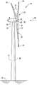
FIG. 1 illustrates a perspective view of one embodiment of a wind turbine according to the present disclosure;
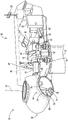
FIG. 2 illustrates an enlarged cross-sectional view of a portion of the wind turbine shown in FIG. 1;
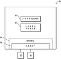
FIG. 3 illustrates a block diagram of one embodiment of suitable components that may be included in a controller of a wind turbine according to the present disclosure;
FIG. 4 illustrates a flow chart of one embodiment of a method for detecting actual slippage in a coupling of a wind turbine power system according to the present disclosure;
FIG. 5 illustrates a schematic view of an embodiment of an implementation of a computer-implemented model of a system for detecting actual slippage in a coupling of a wind turbine power system according to the present disclosure;
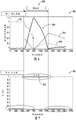
FIG. 6 illustrates a graph of one embodiment of a plurality of sensor signals (y-axis) and a plurality of samples (x-axis) in accordance with the present disclosure, particularly illustrating a slip region including a slip event of a coupling of a wind turbine power system;
FIG. 7 illustrates a graph of one embodiment of a Y variable (Y-axis) and a plurality of samples (x-axis) in accordance with the present disclosure, particularly illustrating the Y variable indicating an actual slip event of a coupling of a wind turbine power system; and
FIG. 8 illustrates a graph of one embodiment from a combination of the graphs of FIG. 6 and FIG. 7 used as an input parameter to a computer-implemented model to determine whether an actual slip event or a no slip event occurred in a coupling of a wind turbine power system.
Detailed Description
Reference will now be made in detail to the various embodiments, one or more examples of which are illustrated in each figure. Each example is provided by way of explanation, not meant as a limitation. For example, features illustrated or described as part of one embodiment can be used on or in conjunction with other embodiments to yield yet further embodiments. It is intended that the present disclosure includes such modifications and variations.
In general, the present disclosure relates to systems and methods for automatically classifying actual slip events upon triggering a corresponding fault in a wind turbine power system. Additionally, the systems and methods of the present disclosure may also estimate the magnitude of slip that may have occurred during the fault, for example, using sensor data from the wind turbine power system. More particularly, in embodiments, for classification purposes, the systems and methods of the present disclosure may evaluate differences in the amplitudes of the sensor signals, rates of change in the sensor signals, and/or absolute amplitudes of the sensor signals to detect differences between marker slip events with actual slip and those in the absence of slip. Such sensor signals may include, for example, generator speed, rotor speed, drive train acceleration, one or more electrical signals, wind speed, pitch angle, system operating conditions, and/or generator torque demand. Further, in embodiments, the sensor signal may be used originally or manipulated based on a signal processing algorithm. Thus, the processed sensor signals may also be used for prediction and estimation. More particularly, in embodiments, to estimate the slip magnitude, an empirical model may be developed based on the reported slip and sensor data over a time duration. Thus, in such embodiments, the model has the inherent ability to improve its prediction based on any new fault data and data available to the sensors.
Referring now to the drawings, FIG. 1 illustrates a perspective view of one embodiment of a wind turbine 10 according to the present disclosure. In the illustrated embodiment, wind turbine 10 is a horizontal-axis wind turbine. Alternatively, wind turbine 10 may be a vertical axis wind turbine. Additionally, as shown, wind turbine 10 includes a tower 12 extending from a support system 14, a nacelle 16 mounted on tower 12, and a rotor 18 coupled to nacelle 16. Rotor 18 includes a rotatable hub 20 and at least one rotor blade 22 coupled to hub 20 and extending outwardly from hub 20. Further, as shown, rotor 18 has three rotor blades 22. In an alternative embodiment, rotor 18 includes more or less than three rotor blades 22. In an embodiment, tower 12 is fabricated from tubular steel to define a cavity (not shown in FIG. 1) between support system 14 and nacelle 16. In an alternative embodiment, tower 12 is any suitable type of tower having any suitable height.
Thus, when wind strikes rotor blades 22 from direction 28, rotor 18 rotates about an axis of rotation 30. As rotor blades 22 are rotated and subjected to centrifugal forces, rotor blades 22 are also subjected to various forces and moments. As such, rotor blades 22 may deflect and/or rotate from a neutral, or non-deflected, position to a deflected position.
Further, the pitch angle or blade pitch (i.e., the perspective of rotor blades 22 with respect to direction 28 of the wind) of rotor blades 22 may be varied by pitch adjustment system 32 to control the load and power generated by wind turbine 10 by adjusting the angular position of at least one rotor blade 22 with respect to the wind vectors. The pitch axis 34 of the rotor blade 22 is shown. During operation of wind turbine 10, pitch adjustment system 32 may change a blade pitch of rotor blades 22 such that rotor blades 22 are moved to a feathered (feathered) position, such that the perspective of at least one rotor blade 22 relative to wind vectors provides a minimum surface area for rotor blade 22 to orient toward the wind vectors, which facilitates reducing a rotational speed of rotor 18 and/or facilitates a stall (stall) of rotor 18.
In one embodiment, the blade pitch of each rotor blade 22 is individually controlled by controller 36. Alternatively, the blade pitch of all rotor blades 22 may be controlled simultaneously by controller 36. Moreover, in embodiments, as direction 28 changes, a yaw direction of nacelle 16 may be controlled about a yaw axis 38 to position rotor blades 22 with respect to direction 28.
In the embodiment, the controller 36 is shown as being centralized within the nacelle 16, however, the controller 36 may be a distributed system throughout the wind turbine 10, on the support system 14, within a wind farm, and/or at a remote control center.
Referring now to FIG. 2, an enlarged cross-sectional view of a portion of wind turbine 10 is illustrated in accordance with the present disclosure. In the embodiment, hub 20 is rotatably coupled to an electric generator 42 positioned within nacelle 16 by a rotor shaft 44 (sometimes referred to as either a main shaft or a low speed shaft), a gearbox 46, a high speed shaft 48, and a coupling 50. In an embodiment, the rotor shaft 44 is disposed coaxially with the longitudinal axis 40. Rotation of rotor shaft 44 rotatably drives gearbox 46, which gearbox 46 in turn drives high speed shaft 48. High speed shaft 48 rotatably drives generator 42 with coupling 50, and rotation of high speed shaft 48 facilitates production of electrical power by generator 42. Gearbox 46 and generator 42 are supported by supports 52, 54. Further, in an embodiment, gearbox 46 utilizes a dual path geometry to drive high speed shaft 48. Alternatively, rotor shaft 44 is coupled directly to generator 42 with coupling 50.
Still referring to FIG. 2, forward and aft support bearings 60 and 62 facilitate radial support and alignment of rotor shaft 44. Forward support bearing 60 is coupled to rotor shaft 44 near hub 20. Aft support bearing 62 is located on rotor shaft 44 near gearbox 46 and/or generator 42. Alternatively, nacelle 16 includes any number of support bearings that enable wind turbine 10 to function as disclosed herein. Rotor shaft 44, generator 42, gearbox 46, high speed shaft 48, coupling 50, and/or any associated fastening, support, and/or securing devices (including, but not limited to, supports 52, 54 and forward and aft support bearings 60, 62) are sometimes referred to as a drive train 64, in this example referred to as a gear drive train.
In other examples, the gear train 64 is replaced by a direct drive train. For example, a relatively long main shaft connects hub 20 and generator 42. The main shaft 44 and the generator shaft 48 are typically coupled via a tapered sleeve (sleeve) coupling. The main shaft 44 is typically supported by a front bearing (e.g., a spherical roller bearing) proximate the hub 20 and a rear bearing (e.g., a CARB bearing) proximate the generator 42. The front and rear bearings are connected to a bedplate (bedplate) and are configured to transfer axial and bending loads to the bedplate mounted to the nacelle 16. The generator 42 is suspended from a main shaft 44. Additional torque beams may be provided between the generator 42 and the foundation to transfer torque to the foundation during operation of the wind turbine 10.
In an embodiment, hub 20 may also include a pitch assembly 66. For example, as shown in fig. 2, pitch assembly 66 includes one or more pitch drive systems 68 and at least one sensor 70. Each pitch drive system 68 is coupled to a respective rotor blade 22 (as shown in FIG. 1) for adjusting the blade pitch of the associated rotor blade 22 along pitch axis 34. Only one of the three pitch drive systems 68 is shown in fig. 2.
In an embodiment, pitch assembly 66 includes at least one pitch bearing 72, which pitch bearing 72 is coupled to hub 20 and to a respective rotor blade 22 (shown in FIG. 1) for rotating the respective rotor blade 22 about pitch axis 34. The pitch drive system 68 includes a pitch drive motor 74, a pitch drive gearbox 76 and a pitch drive pinion 78. The pitch drive motor 74 is coupled to the pitch drive gearbox 76 such that the pitch drive motor 74 imparts mechanical force to the pitch drive gearbox 76. The pitch drive gearbox 76 is coupled to the pitch drive pinion 78 such that the pitch drive pinion 78 is rotated by the pitch drive gearbox 76. The pitch bearing 72 is coupled to the pitch drive pinion 78 such that rotation of the pitch drive pinion 78 causes rotation of the pitch bearing 72. More specifically, in an embodiment, pitch drive pinion 78 is coupled to pitch bearing 72 such that rotation of pitch drive gearbox 76 rotates pitch bearing 72 and rotor blade 22 about pitch axis 34 to change the blade pitch of rotor blade 22. Further, pitch drive system 68 is coupled to controller 36 for adjusting the blade pitch of rotor blades 22 upon receipt of one or more signals from controller 36.
Referring now to fig. 3, a block diagram of one embodiment of suitable components that may be included within controller 36 is illustrated, in accordance with aspects of the present disclosure. It should be appreciated that the various components of the controller of FIG. 3 may be applied to any suitable controller, including, for example, a turbine controller, a wind farm level controller, a supervisory controller, and/or other suitable control systems.
As shown, the controller 36 may include one or more processors 80 and associated memory devices 82 configured to perform various computer-implemented functions (e.g., performing the methods, steps, calculations, etc., disclosed herein). As used herein, the term "processor" refers not only to integrated circuits referred to in the art as being included in a computer, but also refers to controllers, microcontrollers, microcomputers, Programmable Logic Controllers (PLCs), application specific integrated circuits, and other programmable circuits. Additionally, the memory device(s) 82 may generally include memory element(s) including, but not limited to, a computer-readable medium (e.g., Random Access Memory (RAM)), a computer-readable non-volatile medium (e.g., flash memory), a floppy diskette, a compact disk read-only memory (CD-ROM), a magneto-optical disk (MOD), a Digital Versatile Disk (DVD), and/or other suitable memory elements.
In addition, the controller 36 may also include a communication module 84 to facilitate communication between the various components of the wind turbine 10 and the controller 36. For example, the communication module 84 may include a sensor interface 86 (e.g., one or more analog-to-digital converters) that functions to allow signals transmitted by one or more sensors 88, 90 to be converted into signals that can be understood and processed by the controller 36. It should be appreciated that the sensors 88, 90 may be communicatively coupled to the communication module 84 using any suitable components. For example, as shown in fig. 3, sensors 88, 90 are coupled to sensor interface 86 via a wired connection. However, in other embodiments, sensors 88, 90 may be coupled to sensor interface 86 via a wireless connection (e.g., by using any suitable wireless communication protocol known in the art). Accordingly, the processor 80 may be configured to receive one or more signals from the sensors 88, 90.
It should also be understood that any other number or type of sensors may be employed at any location. For example, the sensors 88, 90 may be analog sensors, digital sensors, optical/visual sensors, accelerometers, pressure sensors, angle of attack sensors, vibration sensors, MIMU sensors, fiber optic systems, temperature sensors, wind sensors, acoustic detection and ranging (SODAR) sensors, infrared lasers, light detection and ranging (LIDAR) sensors, radiometers, pitot tubes, sondes (ravinsondes), and/or any other suitable sensors. It should be appreciated that as used herein, the term "monitor" and variations thereof indicate that various sensors of the wind turbine may be configured to provide direct measurements of the monitored parameter or indirect measurements of such parameter. Thus, the sensors 88, 90 may be used, for example, to generate a signal related to the monitored parameter, which may then be used by the controller to determine the actual condition.
Referring now to fig. 4-8, the present disclosure is directed to a method 100 and system 200 for detecting actual slippage in a coupling (e.g., coupling 50 on high speed shaft 48) of a wind turbine 10. In general, the method 100 will be described herein with reference to the wind turbine 10 described above with reference to FIGS. 1-3. However, it should be appreciated by one of ordinary skill in the art that the disclosed method 100 may generally be utilized with any wind turbine having any suitable configuration. Additionally, although fig. 4 depicts steps performed in a particular order for purposes of illustration and discussion, the methods discussed herein are not limited to any particular order or arrangement. Using the disclosure provided herein, those skilled in the art will appreciate that various steps of the methods disclosed herein may be omitted, rearranged, combined, and/or adapted in various ways without departing from the scope of the present disclosure.
As shown at (102), method 100 includes monitoring a plurality of sensor signals related to the coupler via controller 36 for a fault. For example, in an embodiment, the sensor signals may include, for example, generator speed, rotor speed, generator torque demand, driveline acceleration, one or more electrical signals (e.g., current, voltage, etc.), wind speed, pitch angle, system operating conditions, and/or functions thereof. In particular embodiments, the plurality of sensor signals may be raw measurements from one or more sensors, such as sensors 88, 90 of wind turbine 10. Additionally or alternatively, the method 100 may include processing the plurality of sensor signals using one or more processing algorithms.
As shown at (104), the method 100 includes determining whether a fault is detected in the sensor signal. In response to detecting a fault in the plurality of sensor signals associated with the coupling, as shown at (106), method 100 includes determining, via controller 36, that the fault is indicative of an actual slip or no-slip event of coupling 50 using one or more classification parameters. For example, in an embodiment, the classification parameter(s) may include differences in amplitudes of the plurality of sensor signals, rates of change in the plurality of sensor signals, absolute values of the plurality of sensor signals, statistical analysis of the plurality of sensor signals, and/or the like.
In particular embodiments, for example, the controller 36 may use differences in the amplitudes of the plurality of sensor signals, rates of change in the plurality of sensor signals, absolute values of the plurality of sensor signals, or statistical analysis of the plurality of sensor signals to determine whether the fault is an actual slip or no-slip event indicative of the coupling to detect differences between a fault with actual slip and a fault with only no-slip event.
Still referring to FIG. 4, as shown at (108), the method 100 determines that the fault indicates actual slip. Accordingly, as shown at (110), the method 100 includes estimating, via the controller 36, an amplitude of the actual slip using the plurality of sensor signals and the duration of the actual slip. For example, in an embodiment, the method 100 may include estimating the magnitude of the actual slip via at least one of the cloud server or the computer-implemented model 210 programmed in the controller 36 using the plurality of sensor signals and the duration of the actual slip. Thus, this estimation can be performed online or offline. Further, as shown at (112), method 100 includes implementing a control action via controller 36 based on the magnitude of the actual slip in coupling 50.
The system and method of the present disclosure may be further understood with reference now to fig. 5-8. For example, as shown in FIG. 5, a schematic diagram of one embodiment of a system 200 for detecting actual slippage in a coupling, such as a rotating shaft of coupling 50 on high speed shaft 48, is illustrated. As shown, the system 200 may include a controller 36 having various computer modules 202 for implementing the method steps described herein.
In particular, as shown, the input preparation module 204 is configured to receive a plurality of sensor signals related to the coupling for a fault. Additionally, the input preparation module 204 may use machine learning or artificial intelligence to train the input data. Further, as shown in the illustrated embodiment, system 200 can include a model development module 206 that includes computer-implemented model(s) 210. Thus, in embodiments, as shown, model development module 206 receives input data from input preparation module 204 and may develop computer-implemented model(s) 210. In several embodiments, the system 200 may develop a computer-implemented model 210 prior to monitoring a plurality of sensor signals related to the coupling for faults. More particularly, as shown, input preparation module 204 may divide the data into two data sets as shown at 212, for example into training data 214 and test data 216. In such embodiments, as shown, system 200 may train computer-implemented model(s) 210 using at least training data 214. In an embodiment, training data 214 may include, for example, data from wind turbine 10, another wind turbine in the same wind farm, and/or historical data.
Thus, in such embodiments, the training data 214 may be used to learn (or train) the computer-implemented model(s) 210. Further, in certain embodiments, the computer-implemented model(s) 210 may include supervised learning-based algorithms, such as machine learning algorithms or artificial intelligence. Further, as shown, the test data 216 may be used as an input to a model test 220, along with an output 218 of a supervised learning-based algorithm of the computer-implemented model(s) 210, for testing the computer-implemented model(s) 210. In another embodiment, the system 200 may also continuously train and update the computer-implemented model(s) 210 using training data 214, test data 216, output data 218 from supervised learning-based algorithms, and/or new learning data 234.
In such embodiments, model test 220 is configured to provide results 222 indicating whether computer-implemented model(s) 210 are ready to be implemented at the site of wind turbine 10. More particularly, as shown, the system 200 can also include a field test module 208 that evaluates the results 222 by comparing the accuracy of the computer-implemented model(s) 210 (e.g., the results 222) to an accuracy threshold for a duration of time. For example, as shown at 224, when the accuracy of the computer-implemented model(s) 210 is greater than an accuracy threshold (e.g., greater than 70% correct (correct)), the system 200 is configured to further train the computer-implemented model 210 with new learning data 234 from the duration, and then deployed for field testing (as shown at 228 and 232). In contrast, when the accuracy of the computer-implemented model(s) 210 is less than an accuracy threshold (e.g., less than 70% correct rate), the system 200 is configured to adjust or modify the computer-implemented model or receive additional data (as shown at 230).
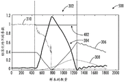
Referring now to fig. 6-8, various diagrams are illustrated to further explain the systems and methods of the present disclosure. In particular, fig. 6 illustrates a graph 300 of one embodiment of a plurality of sensor signals (y-axis) (input variables) versus a plurality of samples (x-axis) according to the present disclosure, particularly illustrating a slip region 302 containing slip events 304 of a coupling of a wind turbine power system. In particular, as shown in the illustrated embodiment, the plurality of sensor signals includes a generator speed 306, a rotor speed 308, and a generator torque request 310. FIG. 7 illustrates a graph 400 of one embodiment of a Y variable (Y-axis) versus a plurality of samples (x-axis) according to the present disclosure, particularly illustrating the Y variable indicating an actual slip event 402 in the slip region 302 of the coupling of the wind turbine 10. In particular, as shown, outside the sliding region 302, the Y variable is equal to zero (0), while in the sliding region 302, the Y variable is equal to one (1). Thus, FIG. 8 illustrates a graph 500 from one embodiment of a combination of the graphs of FIGS. 6 and 7, which may be used as an input parameter to the computer-implemented model 210 to determine whether an actual slip event or a no slip event has occurred in the coupling of the wind turbine 10. Thus, since sensor signals such as generator speed 306, rotor speed 308, and generator torque demand 310 record significant changes during a slip event, these parameters may be monitored to detect a slip event. However, since the same signal may record changes during a no-slip event, the present disclosure also includes monitoring the magnitude and/or rate of change of such signals to distinguish between actual slip events and no-slip events.
Exemplary embodiments of systems for a drive train of a wind turbine are described above in detail. The system is not limited to the specific embodiments described herein, but rather, components of the system may be utilized independently and separately from other components described herein. Rather, the embodiments can be implemented and utilized in connection with many other rotor blade applications.
Although specific features of various embodiments of the disclosure may be shown in some drawings and not in others, this is for convenience only. In accordance with the principles of the present disclosure, any feature of a drawing may be referenced and/or claimed in combination with any feature of any other drawing.
Various aspects and embodiments of the invention are defined by the following numbered clauses:
monitoring, via a controller, a plurality of sensor signals related to the coupling for a fault;
in response to detecting a fault in a plurality of sensor signals associated with the coupling, determining, via the controller, whether the fault is indicative of an actual slip or no slip event of the coupling using one or more classification parameters;
estimating, via the controller, an amplitude of the actual slip using the plurality of sensor signals and a duration of the actual slip when the fault indicates the actual slip; and
implementing, via the controller, a control action based on a magnitude of actual slip in the coupling.
The method of clause 2. the method of clause 1, wherein the plurality of sensor signals includes at least one of: generator speed, rotor speed, generator torque demand, driveline acceleration, one or more electrical signals, wind speed, pitch angle, system operating conditions, or a function thereof.
Clause 3. the method of any of the preceding clauses, wherein the one or more classification parameters include at least one of differences in amplitudes of the plurality of sensor signals, rates of change in the plurality of sensor signals, absolute values of the plurality of sensor signals, or statistical analysis of the plurality of sensor signals.
Clause 4. the method of clause 3, wherein determining whether the fault indicates actual slip or a no slip event of the coupling using one or more classification parameters further comprises:
detecting a difference between a fault with actual slip and a fault with only no slip events using at least one of a median difference in amplitudes of the plurality of sensor signals, a rate of change in the plurality of sensor signals, an absolute value of the plurality of sensor signals, or a statistical analysis of the plurality of sensor signals.
Clause 5. the method of any of the preceding clauses, further comprising estimating, via at least one of a cloud server or a computer-implemented model programmed in the controller, a magnitude of the actual slip using the plurality of sensor signals and the duration of the actual slip.
Clause 6. the method of clause 5, further comprising developing the computer-implemented model using training data and test data.
Clause 7. the method of clause 6, wherein developing the computer-implemented model using training data and test data further comprises:
training the computer-implemented model using at least the training data, the computer-implemented model including one or more supervised learning-based algorithms; and
testing the computer-implemented model using the test data and output data from the one or more supervised learning-based algorithms.
Clause 8. the method of clause 7, further comprising:
comparing the accuracy of the computer-implemented model to an accuracy threshold for the duration;
optionally training the computer-implemented model further with new learning data from the duration when the accuracy of the computer-implemented model is greater than the accuracy threshold; and
adjusting the computer-implemented model or receiving additional data when the accuracy of the computer-implemented model is less than the accuracy threshold.
Clause 9. the method of clause 6, further comprising developing the computer-implemented model using the training data and the test data prior to monitoring the plurality of sensor signals related to the coupling for faults.
Clause 11. the method of any of the preceding clauses, wherein the plurality of sensor signals are raw measurements from one or more sensors.
Clause 13. the method of any of the preceding clauses, wherein the rotating shaft is a high speed shaft of a generator of a wind turbine power system.
a controller comprising at least one processor having at least one computer-implemented model programmed therein, the at least one computer-implemented model configured to implement a plurality of operations comprising:
receiving a plurality of sensor signals associated with the coupling for a fault;
in response to detecting a fault in the plurality of sensor signals associated with the coupling, determining whether the fault is indicative of an actual slip or no slip event of the coupling using one or more classification parameters; and
estimating, via the computer-implemented model, an amplitude of the actual slip using the plurality of sensor signals and a duration of the actual slip when the fault indicates the actual slip,
wherein the at least one processor is configured to implement a control action based on a magnitude of an actual slip in the coupling.
Clause 15. the system of clause 14, wherein the plurality of sensor signals includes at least one of each of: generator speed, rotor speed, generator torque demand, driveline acceleration, one or more electrical signals, wind speed, pitch angle, system operating conditions, or a function thereof.
The system of clause 17. the system of clause 16, wherein determining whether the fault is indicative of actual slip or a no slip event of the coupling using one or more classification parameters further comprises:
detecting a difference between a fault with actual slip and a fault with only no slip events using at least one of differences in amplitudes of the plurality of sensor signals, rates of change in the plurality of sensor signals, or absolute values of the plurality of sensor signals.
a computer-implemented model is developed using the training data and the test data.
The system of clause 19. the system of clause 18, wherein developing the computer-implemented model using training data and test data further comprises:
training the computer-implemented model using at least the training data, the computer-implemented model comprising a supervised learning-based algorithm; and
the computer-implemented model is tested using the test data and output data from the supervised learning-based algorithm.
comparing the accuracy of the computer-implemented model to an accuracy threshold for the duration;
further training the computer-implemented model with new learning data from the duration when the accuracy of the computer-implemented model is greater than the accuracy threshold; and the number of the first and second groups,
adjusting the computer-implemented model or receiving additional data when the accuracy of the computer-implemented model is less than the accuracy threshold;
developing the computer-implemented model using the training data and the test data prior to monitoring the plurality of sensor signals related to the coupling for faults; and
the computer-implemented model is continuously trained and updated using training data, test data, output data from the supervised learning-based algorithm, and new learning data.
This written description uses examples to disclose the disclosure, including the best mode, and also to enable any person skilled in the art to practice the disclosure, including making and using any devices or systems and performing any incorporated methods. . While various specific embodiments have been disclosed in the foregoing, those skilled in the art will recognize that the spirit and scope of the claims allows for equally effective modifications. In particular, mutually non-exclusive features of the embodiments described above may be combined with each other. The patentable scope of the disclosure is defined by the claims, and may include other examples that occur to those skilled in the art. Such other examples are intended to be within the scope of the claims if they include structural elements that do not differ from the literal language of the claims, or if they include equivalent structural elements with insubstantial differences from the literal languages of the claims.
Claims (10)
1. A method for detecting actual slip in a coupling of a rotating shaft, the method comprising:
monitoring, via a controller, a plurality of sensor signals related to the coupling for a fault;
in response to detecting a fault in the plurality of sensor signals associated with the coupling, determining, via the controller, whether the fault is indicative of an actual slip or no slip event of the coupling using one or more classification parameters;
estimating, via the controller, an amplitude of the actual slip using the plurality of sensor signals and a duration of the actual slip when the fault indicates the actual slip; and
implementing, via the controller, a control action based on the magnitude of the actual slip in the coupling.
2. The method of claim 1, wherein the plurality of sensor signals comprises at least one of: generator speed; a rotor speed; a generator torque demand; driveline acceleration; one or more electrical signals; wind speed; a pitch angle; the system operating state or its function.
3. The method of claim 1, wherein the one or more classification parameters comprise at least one of: a difference in the amplitudes of the plurality of sensor signals; a rate of change in the plurality of sensor signals; absolute values of the plurality of sensor signals; or a statistical analysis of the plurality of sensor signals.
4. The method of claim 3, wherein determining whether the fault is indicative of the actual slip or the no-slip event of the coupling using one or more classification parameters further comprises:
detecting a difference between a fault with actual slip and a fault with only no slip events using at least one of differences in amplitudes of the plurality of sensor signals, rates of change in the plurality of sensor signals, absolute values of the plurality of sensor signals, or statistical analysis of the plurality of sensor signals.
5. The method of claim 1, further comprising estimating the magnitude of the actual slip using the plurality of sensor signals and the duration of the actual slip via at least one of a computer-implemented model programmed in the controller or a cloud server.
6. The method of claim 5, further comprising developing the computer-implemented model using training data and testing data.
7. The method of claim 6, wherein developing the computer-implemented model using training data and testing data further comprises:
training the computer-implemented model using at least the training data, the computer-implemented model including one or more supervised learning-based algorithms; and the number of the first and second groups,
testing the computer-implemented model using the test data and output data from the one or more supervised learning-based algorithms.
8. The method of claim 7, further comprising:
comparing the accuracy of the computer-implemented model to an accuracy threshold for the duration;
optionally training the computer-implemented model further with new learning data from the duration when the accuracy of the computer-implemented model is greater than the accuracy threshold; and
adjusting the computer-implemented model or receiving additional data when the accuracy of the computer-implemented model is less than the accuracy threshold.
9. The method of claim 6, further comprising developing the computer-implemented model using the training data and the test data prior to monitoring the plurality of sensor signals related to the coupling for faults.
10. The method of claim 8, further comprising continuously training and updating the computer-implemented model using the training data, the test data, output data from the supervised learning-based algorithm, and the new learning data.
Applications Claiming Priority (2)
| Application Number | Priority Date | Filing Date | Title |
|---|---|---|---|
| US17/199535 | 2021-03-12 | ||
| US17/199,535 US11774324B2 (en) | 2021-03-12 | 2021-03-12 | System and method for detecting actual slip in a coupling of a rotary shaft |
Publications (1)
| Publication Number | Publication Date |
|---|---|
| CN115076045A true CN115076045A (en) | 2022-09-20 |
Family
ID=80683216
Family Applications (1)
| Application Number | Title | Priority Date | Filing Date |
|---|---|---|---|
| CN202210244424.7A Pending CN115076045A (en) | 2021-03-12 | 2022-03-11 | System and method for detecting actual slip in a coupling of a rotating shaft |
Country Status (4)
| Country | Link |
|---|---|
| US (1) | US11774324B2 (en) |
| EP (1) | EP4056843B1 (en) |
| CN (1) | CN115076045A (en) |
| DK (1) | DK4056843T3 (en) |
Families Citing this family (1)
| Publication number | Priority date | Publication date | Assignee | Title |
|---|---|---|---|---|
| CN117571197B (en) * | 2024-01-17 | 2024-03-26 | 绵阳师范学院 | Coupler torque calibration correction method and system |
Family Cites Families (51)
| Publication number | Priority date | Publication date | Assignee | Title |
|---|---|---|---|---|
| US4605107A (en) | 1983-12-12 | 1986-08-12 | Western Gear Corporation | Slip clutch with slip detector and electrical disconnect |
| JPS6152427A (en) | 1984-08-17 | 1986-03-15 | Mitsubishi Motors Corp | Control of minute slip type clutch apparatus |
| DE102007003867A1 (en) | 2007-01-25 | 2008-07-31 | Prüftechnik Dieter Busch AG | Method and apparatus for monitoring a powertrain having a highly flexible coupling |
| EP2053241A1 (en) | 2007-10-24 | 2009-04-29 | Ecotecnia Energias Renovables S.L. | Method for determining fatigue damage in a power train of a wind turbine |
| DE102009039340A1 (en) | 2009-08-29 | 2011-03-03 | Robert Bosch Gmbh | Operating system of a wind turbine and method using the management system |
| CN102639869B (en) | 2009-11-13 | 2015-02-18 | 谢夫勒科技股份两合公司 | GPS automated tracking of mobile monitoring units |
| JP5725833B2 (en) | 2010-01-04 | 2015-05-27 | Ntn株式会社 | Rolling bearing abnormality diagnosis device, wind power generation device and abnormality diagnosis system |
| US8123478B2 (en) | 2010-05-26 | 2012-02-28 | General Electric Company | Systems and methods for monitoring a condition of a rotor blade for a wind turbine |
| US8364424B2 (en) | 2010-07-30 | 2013-01-29 | General Electric Company | System and method for monitoring a wind turbine gearbox |
| EP2431714A1 (en) | 2010-09-21 | 2012-03-21 | Zero-Max Holding DK A/S | Slip measurement assembly |
| DE102010055876A1 (en) | 2010-12-24 | 2012-06-28 | Aerodyn Engineering Gmbh | Gearbox / generator coupling |
| TW201241457A (en) | 2011-04-14 | 2012-10-16 | Univ Chung Yuan Christian | Rotating electrical machine anomaly detecting method and apparatus, and wind generating system |
| US8317462B2 (en) | 2011-04-26 | 2012-11-27 | General Electric Company | System for actively monitoring wear on wind turbine brake pads and related methods |
| US9835136B2 (en) | 2011-09-26 | 2017-12-05 | Vestas Wind Systems A/S | System and method for extending the operating life of a wind turbine gear train based on energy storage |
| DK2824324T3 (en) | 2012-03-08 | 2018-08-06 | Ntn Toyo Bearing Co Ltd | Condition Monitoring |
| CN202645849U (en) | 2012-07-10 | 2013-01-02 | 国电联合动力技术有限公司 | Wind turbine generator state monitoring and fault diagnosing system coupled with control system |
| WO2014164891A1 (en) * | 2013-03-11 | 2014-10-09 | Illing Engineering Service | Wind turbine control system |
| DE102013208084B3 (en) | 2013-05-02 | 2014-05-08 | Senvion Se | Method and system for monitoring a wind turbine and wind turbine |
| JP6407592B2 (en) | 2013-07-22 | 2018-10-17 | Ntn株式会社 | Wind turbine generator abnormality diagnosis device and abnormality diagnosis method |
| US20160187226A1 (en) | 2013-08-01 | 2016-06-30 | Ntn Corporation | Bearing device vibration analysis method, bearing device vibration analyzer, and rolling bearing condition monitoring system |
| US20150134189A1 (en) | 2013-11-08 | 2015-05-14 | Ricardo, Inc. | Systems and methods for remaining useful life predictions in drivetrains |
| CN106471247B (en) | 2014-06-24 | 2019-06-28 | Ntn株式会社 | Condition monitoring system and the wind generator system for using the system |
| US10047726B2 (en) | 2014-07-29 | 2018-08-14 | Ntn Corporation | Condition monitoring system and wind power generation system comprising the same |
| JP6308922B2 (en) | 2014-09-17 | 2018-04-11 | Ntn株式会社 | Rolling bearing abnormality diagnosis apparatus, wind power generation apparatus, and rolling bearing abnormality diagnosis method |
| DK2998812T3 (en) | 2014-09-19 | 2021-10-04 | Laborelec Cvba | Measurement treatment system for condition monitoring of a wind turbine |
| DE102014225637A1 (en) | 2014-12-12 | 2016-06-30 | Robert Bosch Gmbh | Method and device for monitoring a wind energy plant |
| JP6695105B2 (en) | 2015-07-21 | 2020-05-20 | Ntn株式会社 | Wind power generator condition monitoring device |
| JP6553970B2 (en) | 2015-07-24 | 2019-07-31 | Ntn株式会社 | Abnormality diagnosis device and sensor disconnection detection method |
| ES2738351T3 (en) | 2015-11-15 | 2020-01-22 | Adwen Gmbh | Method and device for monitoring a drive train of a wind turbine with elastic coupling |
| ES2613902B1 (en) | 2015-11-26 | 2018-03-14 | Gamesa Innovation & Technology, S.L. | Method and systems for real-time monitoring of the winding generator winding insulation status |
| CN105510026A (en) * | 2015-12-10 | 2016-04-20 | 内蒙古久和能源装备有限公司 | Wind turbine generator system shaft coupling skidding fault detection apparatus and method |
| US11460005B2 (en) | 2016-03-17 | 2022-10-04 | Ntn Corporation | Condition monitoring system and wind turbine generation apparatus |
| JP2017173041A (en) | 2016-03-22 | 2017-09-28 | Ntn株式会社 | State monitor, wind power generation facility having the same, and electrical noise elimination method |
| WO2017170270A1 (en) | 2016-03-30 | 2017-10-05 | Ntn株式会社 | State monitoring system of gear device and state monitoring method |
| KR101764540B1 (en) | 2016-06-21 | 2017-08-02 | 두산중공업 주식회사 | Vibration Monitoring and Diagnosis System for Wind Turbine |
| JP6665062B2 (en) | 2016-08-31 | 2020-03-13 | Ntn株式会社 | Condition monitoring device |
| JP7042448B2 (en) * | 2017-01-25 | 2022-03-28 | パナソニックIpマネジメント株式会社 | Status monitoring system, status monitoring method, and status monitoring program |
| JP2018124117A (en) | 2017-01-31 | 2018-08-09 | Ntn株式会社 | State monitoring system and wind force power generator |
| US11441940B2 (en) | 2017-04-13 | 2022-09-13 | Ntn Corporation | Condition monitoring apparatus, condition monitoring system, and condition monitoring method |
| CN107179503B (en) * | 2017-04-21 | 2020-07-07 | 美林数据技术股份有限公司 | Wind turbine generator fault intelligent diagnosis and early warning method based on random forest |
| US10655607B2 (en) | 2017-06-02 | 2020-05-19 | General Electric Company | Systems and methods for detecting damage in wind turbine bearings |
| CN107178503B (en) * | 2017-07-28 | 2021-06-08 | 广东美芝制冷设备有限公司 | Rotary compressor and refrigerating device |
| US10935001B2 (en) | 2017-11-02 | 2021-03-02 | General Electric Company | System and method for monitoring wear on a gearbox of a wind turbine |
| DE102017131241B4 (en) | 2017-12-22 | 2022-07-14 | fos4X GmbH | Monitoring method for a wind turbine, associated monitoring device and wind turbine with monitoring device |
| CN108757340B (en) | 2018-04-25 | 2020-08-25 | 浙江运达风电股份有限公司 | Method and system for monitoring running real-time state of high-speed shaft of wind driven generator |
| CN108386324B (en) | 2018-04-25 | 2020-04-28 | 浙江运达风电股份有限公司 | Health monitoring method and device for torque limiter of wind driven generator |
| US20200063710A1 (en) * | 2018-08-23 | 2020-02-27 | BluWave Inc. | System and methods for hyper short-term wind power prediction using real-time wind parameter measurements |
| US20200143292A1 (en) * | 2018-11-01 | 2020-05-07 | General Electric Company | Signature enhancement for deviation measurement-based classification of a detected anomaly in an industrial asset |
| CN110174264B (en) | 2019-06-14 | 2021-08-24 | 三一重能股份有限公司 | Wind generating set coupler slippage early warning device, wind driven generator and early warning method |
| CN110132581A (en) | 2019-06-27 | 2019-08-16 | 三一重能有限公司 | A kind of shaft coupling slipping monitoring system and method |
| WO2021137857A1 (en) * | 2019-12-31 | 2021-07-08 | General Electric Company | System and method for detecting anomalies in wind turbine control signals |
-
2021
- 2021-03-12 US US17/199,535 patent/US11774324B2/en active Active
-
2022
- 2022-02-14 DK DK22156546.8T patent/DK4056843T3/en active
- 2022-02-14 EP EP22156546.8A patent/EP4056843B1/en active Active
- 2022-03-11 CN CN202210244424.7A patent/CN115076045A/en active Pending
Also Published As
| Publication number | Publication date |
|---|---|
| US11774324B2 (en) | 2023-10-03 |
| DK4056843T3 (en) | 2023-11-20 |
| US20220291084A1 (en) | 2022-09-15 |
| EP4056843A1 (en) | 2022-09-14 |
| EP4056843B1 (en) | 2023-10-04 |
Similar Documents
| Publication | Publication Date | Title |
|---|---|---|
| DK177769B1 (en) | Methods and apparatus for detecting ice on a rotor vane | |
| US9909563B2 (en) | System and method for monitoring and controlling wind turbine blade deflection | |
| JP6407592B2 (en) | Wind turbine generator abnormality diagnosis device and abnormality diagnosis method | |
| US9366230B2 (en) | System and method for reducing loads acting on a wind turbine in response to transient wind conditions | |
| US8210811B2 (en) | Apparatus and method for operation of a wind turbine | |
| CN203685475U (en) | Wind turbine control system and wind turbine system | |
| CN101542116B (en) | Wind-driven generator | |
| EP3309389B1 (en) | Verification of wind turbine nacelle yaw position sensor | |
| EP2559897A2 (en) | Method and system for detecting an unusual operational condition of a wind turbine | |
| US11098698B2 (en) | System and method for auto-calibrating a load sensor system of a wind turbine | |
| EP3599375A1 (en) | System and method for protecting wind turbines during extreme wind direction change | |
| CN110608134A (en) | System and method for controlling a wind turbine to minimize rotor blade damage | |
| EP4056843B1 (en) | System and method for detecting actual slip in a coupling of a rotary shaft | |
| CN116241413A (en) | System and method for controlling blade pitch on wind turbine rotor blades to reduce vibrations in locked state of the turbine rotor | |
| CN116241412A (en) | System and method for controlling blade pitch of wind turbine rotor blades in an idle state of a rotor hub | |
| JP2022107523A (en) | Thrust control for wind turbines using active sensing of wind turbulence | |
| US11913429B2 (en) | System and method for slip detection and surface health monitoring in a slip coupling of a rotary shaft | |
| US20240068442A1 (en) | System and method for detecting and responding to rotor blade damage in a wind turbine | |
| US20240133360A1 (en) | Protection of wind turbine components during yawing | |
| EP4361434A1 (en) | Protection of wind turbine components during yawing | |
| US20230147218A1 (en) | Methods and systems for determining roughness of wind turbine blades and wind turbine control | |
| CN113565700A (en) | Fan blade state online monitoring device and method based on variable pitch system | |
| CN117980713A (en) | System and method for controlling industrial assets of an asset series |
Legal Events
| Date | Code | Title | Description |
|---|---|---|---|
| PB01 | Publication | ||
| PB01 | Publication | ||
| SE01 | Entry into force of request for substantive examination | ||
| SE01 | Entry into force of request for substantive examination |