CN115074935A - Zipper bleaching and dyeing equipment and bleaching and dyeing process thereof - Google Patents
Zipper bleaching and dyeing equipment and bleaching and dyeing process thereof Download PDFInfo
- Publication number
- CN115074935A CN115074935A CN202210701170.7A CN202210701170A CN115074935A CN 115074935 A CN115074935 A CN 115074935A CN 202210701170 A CN202210701170 A CN 202210701170A CN 115074935 A CN115074935 A CN 115074935A
- Authority
- CN
- China
- Prior art keywords
- bleaching
- dyeing
- zipper
- box body
- fixed mounting
- Prior art date
- Legal status (The legal status is an assumption and is not a legal conclusion. Google has not performed a legal analysis and makes no representation as to the accuracy of the status listed.)
- Pending
Links
- 238000004043 dyeing Methods 0.000 title claims abstract description 90
- 238000004061 bleaching Methods 0.000 title claims abstract description 88
- 238000000034 method Methods 0.000 title claims abstract description 14
- 230000008569 process Effects 0.000 title claims abstract description 13
- 230000005540 biological transmission Effects 0.000 claims description 36
- 239000007788 liquid Substances 0.000 claims description 18
- 230000007246 mechanism Effects 0.000 claims description 18
- 238000009434 installation Methods 0.000 claims description 13
- 230000033001 locomotion Effects 0.000 claims description 11
- 239000003381 stabilizer Substances 0.000 claims description 10
- 238000010438 heat treatment Methods 0.000 claims description 7
- 230000006978 adaptation Effects 0.000 claims description 3
- 230000000903 blocking effect Effects 0.000 abstract description 3
- 230000000694 effects Effects 0.000 description 3
- 238000000926 separation method Methods 0.000 description 3
- 230000009471 action Effects 0.000 description 2
- 230000004888 barrier function Effects 0.000 description 2
- 238000001035 drying Methods 0.000 description 2
- 238000012986 modification Methods 0.000 description 2
- 230000004048 modification Effects 0.000 description 2
- 238000003756 stirring Methods 0.000 description 2
- 238000007605 air drying Methods 0.000 description 1
- 238000013459 approach Methods 0.000 description 1
- 230000009286 beneficial effect Effects 0.000 description 1
- 239000007844 bleaching agent Substances 0.000 description 1
- 238000005034 decoration Methods 0.000 description 1
- 238000011161 development Methods 0.000 description 1
- 230000018109 developmental process Effects 0.000 description 1
- 238000003912 environmental pollution Methods 0.000 description 1
- 239000002244 precipitate Substances 0.000 description 1
- 239000013049 sediment Substances 0.000 description 1
- 230000000087 stabilizing effect Effects 0.000 description 1
- 230000003068 static effect Effects 0.000 description 1
Images


Classifications
-
- D—TEXTILES; PAPER
- D06—TREATMENT OF TEXTILES OR THE LIKE; LAUNDERING; FLEXIBLE MATERIALS NOT OTHERWISE PROVIDED FOR
- D06B—TREATING TEXTILE MATERIALS USING LIQUIDS, GASES OR VAPOURS
- D06B3/00—Passing of textile materials through liquids, gases or vapours to effect treatment, e.g. washing, dyeing, bleaching, sizing, impregnating
- D06B3/30—Passing of textile materials through liquids, gases or vapours to effect treatment, e.g. washing, dyeing, bleaching, sizing, impregnating of articles, e.g. stockings
-
- D—TEXTILES; PAPER
- D06—TREATMENT OF TEXTILES OR THE LIKE; LAUNDERING; FLEXIBLE MATERIALS NOT OTHERWISE PROVIDED FOR
- D06B—TREATING TEXTILE MATERIALS USING LIQUIDS, GASES OR VAPOURS
- D06B23/00—Component parts, details, or accessories of apparatus or machines, specially adapted for the treating of textile materials, not restricted to a particular kind of apparatus, provided for in groups D06B1/00 - D06B21/00
- D06B23/20—Arrangements of apparatus for treating processing-liquids, -gases or -vapours, e.g. purification, filtration, distillation
- D06B23/205—Arrangements of apparatus for treating processing-liquids, -gases or -vapours, e.g. purification, filtration, distillation for adding or mixing constituents of the treating material
-
- D—TEXTILES; PAPER
- D06—TREATMENT OF TEXTILES OR THE LIKE; LAUNDERING; FLEXIBLE MATERIALS NOT OTHERWISE PROVIDED FOR
- D06B—TREATING TEXTILE MATERIALS USING LIQUIDS, GASES OR VAPOURS
- D06B3/00—Passing of textile materials through liquids, gases or vapours to effect treatment, e.g. washing, dyeing, bleaching, sizing, impregnating
- D06B3/34—Driving arrangements of machines or apparatus
-
- F—MECHANICAL ENGINEERING; LIGHTING; HEATING; WEAPONS; BLASTING
- F26—DRYING
- F26B—DRYING SOLID MATERIALS OR OBJECTS BY REMOVING LIQUID THEREFROM
- F26B21/00—Arrangements or duct systems, e.g. in combination with pallet boxes, for supplying and controlling air or gases for drying solid materials or objects
Abstract
The invention discloses zipper bleaching and dyeing equipment and a bleaching and dyeing process thereof, wherein the zipper bleaching and dyeing equipment comprises a bottom plate, supporting plates are fixedly arranged on two sides of the bottom plate, a bleaching and dyeing box body is fixedly arranged on the top of the bottom plate, a drain pipe is fixedly and alternately arranged below one side of the bleaching and dyeing box body, a vertical plate is fixedly arranged on one side of the top of the bottom plate, which is positioned on the bleaching and dyeing box body, and a vertical groove is formed in one side of the vertical plate. According to the zipper bleaching and dyeing equipment and the bleaching and dyeing process thereof, the zipper accessories inside the placing box body are in dynamic state all the time by matching the bottom plate, the supporting plate, the drain pipe, the vertical plate, the movable block, the threaded rod, the connecting piece, the placing box body, the first motor, the second motor, the bleaching and dyeing box body, the cam plate, the double doors, the blocking net, the top plate, the mounting block, the limiting block, the positioning block, the sliding groove, the fixing groove, the first spring and the vertical groove.
Description
Technical Field
The invention relates to the technical field of zipper bleaching and dyeing, in particular to zipper bleaching and dyeing equipment and a bleaching and dyeing process thereof.
Background
The zipper is also called zipper, is two flexible mutually-meshed connecting pieces which can be repeatedly pulled and pulled, is one of the most important inventions in the world for more than one hundred years, relates to articles such as clothes, shoes, hats, cases and the like of all people in all countries in the world, has two functions of practicability and decoration, and becomes an important clothing accessory in the world at present.
However, in the traditional zipper bleaching and dyeing equipment in the market at present, only the zipper accessory is placed into bleaching and dyeing liquid through a container, and in the whole bleaching and dyeing process, the zipper accessory is almost in a static state, so that the surface of the zipper accessory, which is in contact with the container, is not sufficiently bleached and dyed, and certain influence is generated on the attractiveness and quality of the zipper.
Disclosure of Invention
The invention aims to provide zipper bleaching and dyeing equipment and a bleaching and dyeing process thereof, which aim to solve the problems in the background technology.
In order to achieve the purpose, the invention provides the following technical scheme:
a zipper bleaching and dyeing device comprises a bottom plate, wherein supporting plates are fixedly arranged on two sides of the bottom plate, a bleaching and dyeing box body is fixedly arranged on the top of the bottom plate, a drain pipe is fixedly and alternately arranged below one side of the bleaching and dyeing box body, a vertical plate is fixedly arranged on one side of the top of the bottom plate, a vertical groove is formed in one side of the vertical plate, a first motor is fixedly arranged on the top of the vertical plate, a threaded rod is fixedly arranged at the driving end of the first motor, a movable block is sleeved on the outer wall of the threaded rod, a connecting piece is fixedly arranged on one side of the movable block, a positioning block is fixedly arranged below one side of the connecting piece, a fixing groove is formed in one side of the positioning block, sliding grooves are formed in the top and the bottom of the inner wall of the fixing groove, two sliding grooves are respectively and slidably arranged with a limiting block, and a mounting block is fixedly arranged between the two limiting blocks, one side fixed mounting of installation piece has the first spring of a plurality of, the opposite side fixed mounting of installation piece has places the box, the top of placing the box is provided with two doors, two tops of opening the door and the bottom of placing the box are all fixed to be inlayed and are installed the barrier net, one side fixed mounting of backup pad has the mounting panel, the top fixed mounting of mounting panel has the second motor, the drive end of second motor rotates with the sealed bearing who bleaches and dye the installation on the box inner wall bottom and is connected, the drive end fixed mounting of second motor has the cam plate.
As a further scheme of the invention: the utility model discloses a dyeing machine, including bottom plate, transmission shaft, second motor drive end, the top of bottom plate is located the opposite side fixed mounting who bleaches the dyeing box and has cylindric box, the rotary drum is installed in the top interlude of cylindric box, the horizontal case is installed to the top fixed interlude of rotary drum, one side fixed inlay of horizontal bottom of the case portion installs the graticule mesh, the transmission shaft is installed to the internal rotation of cylindric box, be provided with second drive mechanism between transmission shaft and the second motor drive end, one side of horizontal top of the case portion is rotated and is installed the pivot, be provided with first drive mechanism between pivot and the transmission shaft, fixed mounting has a plurality of blade on the outer wall of pivot, the top of horizontal incasement wall is located the below fixed mounting of blade and has the heating rod.
As a still further scheme of the invention: the upper side of the outer surface of the cylindrical box body is fixedly sleeved with a fixed rotating plate, the top of the fixed rotating plate is provided with a slide way, one side of the transverse box is fixedly provided with a fixed plate, the bottom of the fixed plate is fixedly provided with a stabilizer bar, and one end of the stabilizer bar is fixedly provided with a sliding block.
As a still further scheme of the invention: the slide opening has been seted up to one side of fixed commentaries on classics board, the cross slot has been seted up on the inner wall of slide opening, the inside fixed mounting of cross slot has the horizontal pole, the cover is equipped with the reset block on the outer wall of horizontal pole, the second spring has been cup jointed to the one side that lies in the reset block on the outer wall of horizontal pole, the bottom fixed mounting of reset block has the locating lever, set up the screens groove with locating lever looks adaptation on the slider, the one end fixed mounting of locating lever has the handle.
As a still further scheme of the invention: the slider is in an inverted T shape and is matched with the slide way.
As a still further scheme of the invention: the movable block is characterized in that a top plate is fixedly embedded in one side of the placing box body, a threaded hole matched with the threaded rod is formed in the top of the movable block, and the movable block is in threaded connection with the threaded rod through the threaded hole formed in the top of the movable block.
As a still further scheme of the invention: the first transmission mechanism and the second transmission mechanism are composed of a driving wheel, a driven wheel and a belt, and the driving wheel and the driven wheel are in transmission connection through the belt.
As a still further scheme of the invention: one side of the reset block is provided with a sliding hole matched with the cross rod, and the reset block is connected with the cross rod in a sliding mode through the sliding hole formed in one side of the reset block.
Compared with the prior art, the invention has the beneficial effects that:
1. the invention uses the matching of the bottom plate, the support plate, the drain pipe, the vertical plate, the movable block, the threaded rod, the connecting piece, the placing box body, the first motor, the second motor, the bleaching and dyeing box body, the cam plate, the double doors, the blocking net, the top plate, the mounting block, the limiting block, the positioning block, the sliding chute, the fixed groove, the first spring and the vertical groove, the placing box body can continuously do a transverse reciprocating motion through the continuous rotation of the cam plate, so that the zipper accessories inside the placing box body are always in a dynamic state, the reciprocating motion of the placing box body can also generate a stirring to the bleaching and dyeing liquid inside the bleaching and dyeing box body, the bleaching and dyeing liquid can also be always in a dynamic state inside the bleaching and dyeing box body, the generation of sediments of the bleaching and dyeing liquid can be avoided, the bleaching and dyeing liquid can be always in a uniform state, a good bleaching and dyeing effect on the zipper accessories can be achieved, and the zipper accessories inside the placing box body are always in a dynamic state, each surface of the zipper accessory can be fully contacted with the bleaching and dyeing liquid, so that the zipper accessory can be fully bleached and dyed, and the final attractiveness and quality of the zipper are ensured.
2. The invention uses the matching of a sliding block, a transverse box, a heating rod, a grid, blades, a rotating shaft, a first transmission mechanism, a fixed plate, a rotating drum, a stabilizing rod, a second transmission mechanism, a transmission shaft, a cylindrical box body, a handle, a fixed rotating plate, a slideway, a reset block, a transverse groove, a second spring, a transverse rod, a positioning rod, a sliding hole and a clamping groove to dry the zipper accessory in the box body, the top of the box body is matched with the barrier net at the bottom of the box body, so that hot air enters the inside of the box body to achieve a good circulation state, the zipper accessory in the box body can be dried quickly, meanwhile, in the process of drying the zipper accessory, the box body is still positioned in the opening range of the top of the bleaching and dyeing box body, some residual bleaching and dyeing liquid which drips can not drip everywhere, and can not flow back to the inside of the bleaching and dyeing box body, and the bleaching and dyeing liquid can not be discharged everywhere, cause the pollution of environment, accomplish when the zip fastener and float and dye the back, rotate horizontal case to keeping away from the top of placing the box top, then alright take the inside zip fastener accessory of placing the box, consequently, mobility through horizontal case, avoided when loading and unloading zip fastener accessory placing the box inside, horizontal case can lead to the fact to stop to it, and horizontal case is rotating the in-process, through the fixed plate, the stabilizer bar, the slider, the cooperation of slide and fixed commentaries on classics board plays the effect of a support to horizontal case, improve stability of horizontal case, avoid horizontal case to rely on the rotary drum single-point atress, the time is permanent, the phenomenon of emergence rotary drum rupture.
Drawings
FIG. 1 is a schematic structural view of a zipper bleaching and dyeing apparatus;
FIG. 2 is a top view of a box body in the zipper bleaching and dyeing apparatus;
FIG. 3 is a front view of a cylindrical box and a fixed rotating plate in a zipper bleaching and dyeing apparatus;
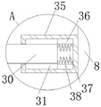
FIG. 4 is an enlarged view of the structure A in FIG. 1 of a zipper bleaching and dyeing apparatus;
FIG. 5 is an enlarged view of the zipper bleaching and dyeing apparatus shown at B in FIG. 1;
FIG. 6 is an enlarged view of the zipper bleaching and dyeing apparatus shown at C in FIG. 5.
In the figure: the bottom plate 1, the backup pad 2, the drain pipe 3, the riser 4, the slider 5, the movable block 6, the threaded rod 7, the connecting piece 8, place the box 9, first motor 10, horizontal case 11, heating rod 12, the graticule mesh 13, blade 14, pivot 15, first drive mechanism 16, fixed plate 17, rotary drum 18, stabilizer bar 19, second drive mechanism 20, second motor 21, mounting panel 22, the box 23 of bleaching and dyeing, transmission shaft 24, cam plate 25, cylindric box 26, two divisions of door 27, separation net 28, roof 29, installation piece 30, stopper 31, handle 32, fixed rotary plate 33, slide 34, locating piece 35, spout 36, fixed slot 37, first spring 38, reset block 39, horizontal groove 40, second spring 41, horizontal pole 42, locating lever 43, slide opening 44, screens groove 45, vertical groove 46.
Detailed Description
The technical solutions in the embodiments of the present invention will be clearly and completely described below with reference to the drawings in the embodiments of the present invention, and it is obvious that the described embodiments are only a part of the embodiments of the present invention, and not all of the embodiments. All other embodiments, which can be derived by a person skilled in the art from the embodiments given herein without making any creative effort, shall fall within the protection scope of the present invention.
Referring to fig. 1 to 6, in an embodiment of the present invention, a zipper bleaching and dyeing apparatus includes a bottom plate 1, support plates 2 are fixedly installed on both sides of the bottom plate 1, a bleaching and dyeing box 23 is fixedly installed on the top of the bottom plate 1, a drain pipe 3 is fixedly inserted and installed below one side of the bleaching and dyeing box 23, one end of the drain pipe 3 penetrates through the top of the bottom plate 1 and extends to below the bottom of the bottom plate 1, a vertical plate 4 is fixedly installed on one side of the top of the bottom plate 1, a vertical groove 46 is formed on one side of the vertical plate 4, a first motor 10 is fixedly installed on the top of the vertical plate 4, a driving end of the first motor 10 penetrates through the top of the vertical plate 4 and extends to the inside of the vertical groove 46, a threaded rod 7 is fixedly installed on the driving end of the first motor 10, the bottom end of the threaded rod 7 is rotatably connected with a bearing installed on the bottom of the inner wall of the vertical groove 46, a movable block 6 is sleeved on the outer wall of the threaded rod 7, a movable block 6 is connected with a vertical groove 46 in a sliding manner, a connecting piece 8 is fixedly arranged on one side of the movable block 6, a positioning block 35 is fixedly arranged below one side of the connecting piece 8, a fixing groove 37 is arranged on one side of the positioning block 35, sliding grooves 36 are respectively arranged at the top and the bottom of the inner wall of the fixing groove 37, limiting blocks 31 are respectively and slidably arranged on the two sliding grooves 36, an installation block 30 is fixedly arranged between the two limiting blocks 31, the installation block 30 is connected with the fixing groove 37 in a sliding manner, a plurality of first springs 38 are fixedly arranged on one side of the installation block 30, one end of each first spring 38 is fixedly connected with one side of the inner wall of the fixing groove 37, a placing box body 9 is fixedly arranged on the other side of the installation block 30, a double door 27 is arranged at the top of the placing box body 9, a blocking net 28 is fixedly embedded at the top of the double door 27 and the bottom of the placing box body 9, and an installation plate 22 is fixedly arranged on one side of a support plate 2, the top fixed mounting of mounting panel 22 has second motor 21, and the drive end of second motor 21 runs through the bottom of bottom plate 1 and the bottom of bleaching and dyeing box 23 in proper order and extends to the inside of bleaching and dyeing box 23, and the drive end of second motor 21 is connected with the sealed bearing rotation of installing on bleaching and dyeing box 23 inner wall bottom, and the drive end fixed mounting of second motor 21 has cam plate 25.
Referring to fig. 1, 2 and 4, in the present application, a cylindrical box 26 is fixedly installed on the other side of the top of the bottom plate 1, which is located on the bleaching and dyeing box 23, a rotating drum 18 is installed on the top of the cylindrical box 26 in an inserting manner, the rotating drum 18 is rotatably connected with a bearing installed on the top of the cylindrical box 26, a horizontal box 11 is fixedly installed on the top of the rotating drum 18 in an inserting manner, a grid 13 is fixedly installed on one side of the bottom of the horizontal box 11 in an inserting manner, a transmission shaft 24 is rotatably installed inside the cylindrical box 26, the bottom end of the transmission shaft 24 sequentially penetrates through the bottom of the inner wall of the cylindrical box 26 and the top of the bottom plate 1 and extends to the lower side of the bottom plate 1, a second transmission mechanism 20 is arranged between the transmission shaft 24 and the driving end of a second motor 21, the top end of the transmission shaft 24 penetrates through the inside of the rotating drum 18 and is rotatably connected with the bearing installed on the top of the inner wall of the horizontal box 11, a rotating shaft 15 is rotatably installed on one side of the top of the horizontal box 11, a first transmission mechanism 16 is arranged between the rotating shaft 15 and the transmission shaft 24, a plurality of blades 14 are fixedly installed on the outer wall of the rotating shaft 15, and a heating rod 12 is fixedly installed below the blades 14 at the top of the inner wall of the transverse box 11.
Referring to fig. 3, 5 and 6, in the present application, a fixed rotating plate 33 is fixedly sleeved on an upper side of an outer surface of the cylindrical box 26, a slide way 34 is formed on a top of the fixed rotating plate 33, a fixed plate 17 is fixedly mounted on one side of the horizontal box 11, a stabilizer bar 19 is fixedly mounted on a bottom of the fixed plate 17, a slider 5 is fixedly mounted on one end of the stabilizer bar 19, and the slider 5 is slidably connected with the slide way 34.
Referring to fig. 6, in the application, one side of fixed commentaries on classics board 33 has seted up slide opening 44, transverse groove 40 has been seted up on slide opening 44's the inner wall, the inside fixed mounting of transverse groove 40 has horizontal pole 42, the cover is equipped with reset block 39 on horizontal pole 42's the outer wall, and reset block 39 and transverse groove 40 sliding connection, the second spring 41 has been cup jointed to the one side that is located reset block 39 on horizontal pole 42's the outer wall, reset block 39's bottom fixed mounting has locating lever 43, and locating lever 43 and slide opening 44 sliding connection, set up the screens groove 45 with locating lever 43 looks adaptation on the slider 5, the one end fixed mounting of locating lever 43 has handle 32.
Referring to fig. 6, in the present application, the slider 5 has an inverted T-shape, and the slider 5 is fitted to the slide 34.
Referring to fig. 1 and 2, in the present application, a top plate 29 is fixedly mounted on one side of the housing 9, a threaded hole adapted to the threaded rod 7 is formed at the top of the movable block 6, and the movable block 6 is in threaded connection with the threaded rod 7 through the threaded hole formed at the top thereof.
Referring to fig. 1, in the present application, each of the first transmission mechanism 16 and the second transmission mechanism 20 is composed of a driving wheel, a driven wheel and a belt, and the driving wheel and the driven wheel are in transmission connection through the belt.
Referring to fig. 6, in the present application, a sliding hole adapted to the cross bar 42 is formed at one side of the reset block 39, and the reset block 39 is slidably connected to the cross bar 42 through the sliding hole formed at one side thereof.
The working principle of the invention is as follows:
referring to fig. 1 to 6, when the zipper accessory is used, the electrical components appearing in the present application are all externally connected with a power supply and a control switch, when the zipper accessory is required to be bleached, the first motor 10 is controlled by the switch to start working, the driving end of the first motor 10 drives the threaded rod 7 to rotate, the movable block 6 is stably vertically moved through the threaded transmission of the threaded rod 7 and the movable block 6 and the sliding relation between the movable block 6 and the vertical groove 46, the movable block 6 is moved to drive the connecting piece 8 to move, the connecting piece 8 is moved to drive the positioning block 35 to move, the box 9 is driven to vertically move through the matching of the positioning block 35, the sliding groove 36, the limiting block 31 and the mounting block 30, after the box 9 is moved up to a proper position, the double-open door 27 at the top of the box 9 is manually opened, and then the zipper accessory is completely placed inside the box 9, and the double door 27 is closed, then the placing box body 9 is moved downwards to the inside of the bleaching and dyeing box body 23, the top plate 29 on one side of the placing box body 9 is contacted with one side of the cam plate 25 close to the center, simultaneously bleaching and dyeing liquid can be injected into the bleaching and dyeing box body 23 through the top opening of the bleaching and dyeing box body 23, after a proper amount of bleaching and dyeing liquid is injected, the bleaching and dyeing liquid can enter the inside of the placing box body 9 through the top plate 29 on the top and the bottom of the placing box body 9 to bleach and dye the zipper fittings placed in the placing box body 9, meanwhile, the second motor 21 can be controlled to work through a switch, the driving end of the second motor 21 drives the cam plate 25 to rotate, when one side of the cam plate 25 far from the center is close to the top plate 29, a rightward force can be given to the top plate 29, the placing box body 9 is driven to move rightwards through the top plate 29, the movement of the placing box body 9 can drive the mounting block 30 to slide on the fixing groove 37, the movement of the mounting block 30 drives the limiting block 31 to slide on the sliding groove 36, and the movement of the mounting block 30 extrudes the first spring 38, when the side of the cam plate 25 close to the center approaches to the placing box 9, at the same time, the cam plate 25 loses the thrust on the top plate 29 on one side of the placing box 9, and under the elastic action of the first spring 38, the placing box 9 is driven to reset through the mounting block 30, so that the placing box 9 continuously performs a transverse reciprocating motion through the continuous rotation of the cam plate 25, so that the zipper accessories inside the placing box 9 are always in a dynamic state, and meanwhile, the reciprocating motion of the placing box 9 can also generate a stirring to the bleaching and dyeing liquid inside the bleaching and dyeing box 23, so that the bleaching and dyeing liquid can also be always in a dynamic state inside the bleaching and dyeing box 23, thereby avoiding the bleaching and dyeing liquid from generating precipitates and always being in an even state, reach a good effect of bleaching and dyeing to the zip fastener accessory, place the inside zip fastener accessory of box 9 simultaneously and be in the developments always for each face of zip fastener accessory can both be abundant contact with the bleaching and dyeing liquid, make the bleaching and dyeing that the zip fastener accessory can be abundant, guarantee the final pleasing to the eye of zip fastener and quality.
Referring to fig. 1-6, in use, after the zipper is bleached and dyed, the placing box 9 is moved up to a designated position, the position is close to the horizontal box 11, the second motor 21 is turned on again, the rotation of the driving end of the second motor 21 drives the transmission shaft 24 to rotate through the transmission action of the second transmission mechanism 20, the rotation of the transmission shaft 24 drives the rotation shaft 15 to rotate through the transmission of the first transmission mechanism 16, the rotation of the rotation shaft 15 drives the blades 14 to rotate, the rotation of the blades 14 generates a high-speed airflow to form wind, meanwhile, the heating rod 12 is electrified to heat the wind generated by the rotation of the blades 14, the heated wind is blown out through the grid 13, then the wind is directly blown into the placing box 9 through the separation net 28 at the top of the placing box 9, the zipper accessory inside the placing box 9 is dried, and the top of the placing box 9 is matched with the separation net 28 at the bottom of the placing box 9, the hot air enters the inside of the placing box body 9 to achieve a good circulation state, zipper accessories inside the placing box body 9 can be quickly dried, meanwhile, in the process of drying the zipper accessories, the placing box body 9 is still positioned in the range of the opening at the top of the bleaching and dyeing box body 23, some residual bleaching and dyeing liquid which drips can not drip everywhere and can flow back to the inside of the bleaching and dyeing box body 23, the bleaching and dyeing liquid is prevented from being discharged everywhere to cause environmental pollution, after the zipper is bleached and dyed, the handle 32 can be held and pulled, the positioning rod 43 is driven by the movement of the handle 32 to slide in the sliding hole 44, the reset block 39 is driven by the movement of the positioning rod 43 to slide on the outer wall of the cross rod 42, the reset block 39 can extrude the second spring 41, meanwhile, the movement of the positioning rod 43 can be separated from the inside of the clamping groove 45 on the sliding block 5, so that the positioning rod 43 loses the limit of the sliding block 5, on the contrary, the position of the transverse box 11 can not rotate freely under the fixed relationship of the stabilizer bar 19, the fixed plate 17 and the transverse box 11 by the positioning rod 43, so as to ensure the stable operation of the air drying operation, after the slider 5 loses the position limitation of the positioning rod 43, the slider 5 can rotate freely on the slide way 34, so that the transverse box 11 can rotate freely through the rotating relationship between the rotary drum 18 and the cylindrical box 26, the transverse box 11 rotates to the upper part far away from the top of the placing box 9, and then the zipper accessory in the placing box 9 can be taken out, therefore, the transverse box 11 can block the zipper accessory when the zipper accessory is assembled and disassembled in the placing box 9 through the mobility of the transverse box 11, and the transverse box 11 plays a supporting role on the transverse box 11 through the matching of the fixed plate 17, 19, the slider 5, the slide way 34 and the fixed rotating plate 33 in the rotation process of the stabilizer bar, the stability of the transverse box 11 is improved, the phenomenon that the transverse box 11 is stressed by the single point of the rotary drum 18 and is broken off by the rotary drum 18 within a long time is avoided.
Although the present invention has been described in detail with reference to the foregoing embodiments, it will be apparent to those skilled in the art that various changes in the embodiments and/or modifications of the invention can be made, and equivalents and modifications of some features of the invention can be made without departing from the spirit and scope of the invention.
Claims (9)
1. The zipper bleaching and dyeing equipment and the bleaching and dyeing process thereof comprise a bottom plate (1), and are characterized in that: the utility model discloses a dyeing machine, including bottom plate (1), top fixed mounting of bottom plate (1) has the box of dying (23) of bleaching, the below fixed interlude of dying box (23) one side installs drain pipe (3), one side fixed mounting that the top of bottom plate (1) is located the box of dying (23) has riser (4), erect groove (46) have been seted up to one side of riser (4), the top fixed mounting of riser (4) has first motor (10), the drive end fixed mounting of first motor (10) has threaded rod (7), the cover is equipped with movable block (6) on the outer wall of threaded rod (7), one side fixed mounting of movable block (6) has connecting piece (8), the below fixed mounting of connecting piece (8) one side has locating piece (35), fixed slot (37) have been seted up to one side of locating piece (35), the top and the bottom of fixed slot (37) inner wall have all been seted up spout (36), two equal slidable mounting has stopper (31) on spout (36), two fixed mounting has installation piece (30) between stopper (31), one side fixed mounting of installation piece (30) has a plurality of first spring (38), the opposite side fixed mounting of installation piece (30) has places box (9), the top of placing box (9) is provided with two door (27), two top and the bottom of placing box (9) of opening door (27) are all fixed the inlaying and are installed and hinder and separate net (28), one side fixed mounting of backup pad (2) has mounting panel (22), the top fixed mounting of mounting panel (22) has second motor (21), the drive end of second motor (21) is connected with the sealed bearing rotation of floating and dying the installation on box (23) inner wall bottom, and a cam plate (25) is fixedly arranged at the driving end of the second motor (21).
2. The zipper bleaching and dyeing apparatus according to claim 1, wherein: the top of the bottom plate (1) is positioned at the other side of the bleaching and dyeing box body (23) and is fixedly provided with a cylindrical box body (26), the top of the cylindrical box body (26) is provided with a rotary drum (18) in an inserting way, the top of the rotary drum (18) is fixedly provided with a transverse box (11) in an inserting way, one side of the bottom of the transverse box (11) is fixedly embedded with a grid (13), a transmission shaft (24) is rotatably arranged in the cylindrical box body (26), a second transmission mechanism (20) is arranged between the transmission shaft (24) and the driving end of the second motor (21), a rotating shaft (15) is rotatably arranged on one side of the top of the transverse box (11), a first transmission mechanism (16) is arranged between the rotating shaft (15) and the transmission shaft (24), a plurality of blades (14) are fixedly arranged on the outer wall of the rotating shaft (15), the top of the inner wall of the transverse box (11) is fixedly provided with a heating rod (12) below the blades (14).
3. The zipper bleaching and dyeing apparatus according to claim 2, wherein: the fixed board (33) that changes that has cup jointed of upside of cylindric box (26) surface, slide (34) have been seted up at the top of fixed board (33) that changes, one side fixed mounting of horizontal case (11) has fixed plate (17), the bottom fixed mounting of fixed plate (17) has stabilizer bar (19), the one end fixed mounting of stabilizer bar (19) has slider (5).
4. A zipper bleaching and dyeing apparatus according to claim 3, characterized in that: slide opening (44) have been seted up to one side of fixed commentaries on classics board (33), transverse groove (40) have been seted up on the inner wall of slide opening (44), the inside fixed mounting of transverse groove (40) has horizontal pole (42), the cover is equipped with reset block (39) on the outer wall of horizontal pole (42), second spring (41) have been cup jointed to the one side that is located reset block (39) on the outer wall of horizontal pole (42), the bottom fixed mounting of reset block (39) has locating lever (43), set up screens groove (45) with locating lever (43) looks adaptation on slider (5), the one end fixed mounting of locating lever (43) has handle (32).
5. A zipper bleaching and dyeing apparatus according to claim 3, characterized in that: the slider (5) is in an inverted T shape, and the slider (5) is matched with the slide way (34).
6. The zipper bleaching and dyeing apparatus according to claim 1, wherein: one side of the placing box body (9) is fixedly embedded with a top plate (29), the top of the movable block (6) is provided with a threaded hole matched with the threaded rod (7), and the movable block (6) is in threaded connection with the threaded rod (7) through the threaded hole formed in the top of the movable block.
7. The zipper bleaching and dyeing apparatus according to claim 2, wherein: the first transmission mechanism (16) and the second transmission mechanism (20) are composed of a driving wheel, a driven wheel and a belt, and the driving wheel and the driven wheel are in transmission connection through the belt.
8. The zipper bleaching and dyeing apparatus according to claim 4, wherein: one side of the reset block (39) is provided with a sliding hole matched with the cross rod (42), and the reset block (39) is connected with the cross rod (42) in a sliding mode through the sliding hole formed in one side of the reset block.
9. A bleaching and dyeing process flow of zipper bleaching and dyeing equipment is characterized in that: the bleaching and dyeing process flow of the zipper bleaching and dyeing equipment comprises the following steps:
s1, the placing box body (9) is moved up to a specified position by the driving of the first motor (10), and the zipper fittings needing bleaching and dyeing are placed in the placing box body (9);
s2, resetting the placing box body (9) in the S1 to a designated position inside the bleaching and dyeing box body (23) through the driving of the first motor (10), and enabling a top plate (29) at one side of the placing box body (9) to be abutted against the cam plate (25);
s3, injecting a proper amount of bleaching and dyeing liquid into the bleaching and dyeing box body (23), and simultaneously enabling the placing box body (9) to do a transverse reciprocating motion through the driving of a second motor (21);
s4, after the zipper accessory in the S3 is bleached and dyed, the placing box body (9) is moved up to a specified position through the driving of the first motor (10), the moving blade (14) is driven to rotate through the driving of the second motor (21), meanwhile, the heating rod (12) is started to heat the wind generated by the blade (14), and the generated hot wind dries the zipper accessory in the placing box body (9);
and S5, after the zipper accessories in the S4 are dried, the handle (32) is pulled to enable the clamping groove (45) to lose the limit on the sliding block (5), the position of the transverse box (11) is adjusted, and then the zipper accessories which are bleached, dyed and dried in the box body (9) can be taken out.
Priority Applications (1)
| Application Number | Priority Date | Filing Date | Title |
|---|---|---|---|
| CN202210701170.7A CN115074935A (en) | 2022-06-21 | 2022-06-21 | Zipper bleaching and dyeing equipment and bleaching and dyeing process thereof |
Applications Claiming Priority (1)
| Application Number | Priority Date | Filing Date | Title |
|---|---|---|---|
| CN202210701170.7A CN115074935A (en) | 2022-06-21 | 2022-06-21 | Zipper bleaching and dyeing equipment and bleaching and dyeing process thereof |
Publications (1)
| Publication Number | Publication Date |
|---|---|
| CN115074935A true CN115074935A (en) | 2022-09-20 |
Family
ID=83253097
Family Applications (1)
| Application Number | Title | Priority Date | Filing Date |
|---|---|---|---|
| CN202210701170.7A Pending CN115074935A (en) | 2022-06-21 | 2022-06-21 | Zipper bleaching and dyeing equipment and bleaching and dyeing process thereof |
Country Status (1)
| Country | Link |
|---|---|
| CN (1) | CN115074935A (en) |
Citations (7)
| Publication number | Priority date | Publication date | Assignee | Title |
|---|---|---|---|---|
| CN205989404U (en) * | 2015-05-11 | 2017-03-01 | 迪芬巴赫机械工程有限公司 | It is used for during production material plate in a press blank spreads to device and the plate of material on the molding band of loop back |
| CN108914453A (en) * | 2018-09-05 | 2018-11-30 | 佛山市三创针织有限公司 | A kind of knitwear rapid dyeing device |
| CN211926417U (en) * | 2020-04-21 | 2020-11-13 | 绍兴市水邦针纺股份有限公司 | Quick drying equipment for producing and processing bleached and dyed knitwear |
| CN113249897A (en) * | 2021-07-14 | 2021-08-13 | 江苏红金顶织造有限公司 | Textile fabric fully soaking bleaching and dyeing device for textile processing |
| CN214400996U (en) * | 2021-03-04 | 2021-10-15 | 淮安君腾纺织有限公司 | Gray fabric bleaching and dyeing device capable of achieving uniform coloring |
| DE212020000585U1 (en) * | 2020-12-18 | 2021-12-15 | Suzhou Ailifang Clothing Co., Ltd. | A fully automatic fabric printing and dyeing device |
| CN114150407A (en) * | 2021-10-20 | 2022-03-08 | 浙江凯悦纺织股份有限公司 | Antibacterial polyester yarn stranded wire processing device |
-
2022
- 2022-06-21 CN CN202210701170.7A patent/CN115074935A/en active Pending
Patent Citations (7)
| Publication number | Priority date | Publication date | Assignee | Title |
|---|---|---|---|---|
| CN205989404U (en) * | 2015-05-11 | 2017-03-01 | 迪芬巴赫机械工程有限公司 | It is used for during production material plate in a press blank spreads to device and the plate of material on the molding band of loop back |
| CN108914453A (en) * | 2018-09-05 | 2018-11-30 | 佛山市三创针织有限公司 | A kind of knitwear rapid dyeing device |
| CN211926417U (en) * | 2020-04-21 | 2020-11-13 | 绍兴市水邦针纺股份有限公司 | Quick drying equipment for producing and processing bleached and dyed knitwear |
| DE212020000585U1 (en) * | 2020-12-18 | 2021-12-15 | Suzhou Ailifang Clothing Co., Ltd. | A fully automatic fabric printing and dyeing device |
| CN214400996U (en) * | 2021-03-04 | 2021-10-15 | 淮安君腾纺织有限公司 | Gray fabric bleaching and dyeing device capable of achieving uniform coloring |
| CN113249897A (en) * | 2021-07-14 | 2021-08-13 | 江苏红金顶织造有限公司 | Textile fabric fully soaking bleaching and dyeing device for textile processing |
| CN114150407A (en) * | 2021-10-20 | 2022-03-08 | 浙江凯悦纺织股份有限公司 | Antibacterial polyester yarn stranded wire processing device |
Similar Documents
| Publication | Publication Date | Title |
|---|---|---|
| CN208379224U (en) | A kind of clothing automatic processing device | |
| CN115074935A (en) | Zipper bleaching and dyeing equipment and bleaching and dyeing process thereof | |
| CN209489394U (en) | A kind of production various shapes formula flour stranding machine | |
| CN108049139A (en) | A kind of Domestic automatic ironing device | |
| CN206678682U (en) | A kind of fine arts gouache airing device | |
| CN107385721B (en) | A kind of garment production dyeing apparatus | |
| CN211330072U (en) | Gluing device for shoemaking | |
| CN206768417U (en) | A kind of garment dyeing machine | |
| CN207248712U (en) | A kind of non-yellowing test machine | |
| CN107351571A (en) | Quick-drying water writes formula calligraphy and painting exerciser | |
| CN216204891U (en) | Agricultural seed engineering is with energy-concerving and environment-protective seed desiccator | |
| CN218989686U (en) | Ironing auxiliary equipment and ironing device | |
| CN108750184A (en) | A kind of Intelligent mobile terminal maintenance equipment | |
| KR20090078964A (en) | Supplemental cloth treating apparatus | |
| CN108999383A (en) | A kind of painting device of azoic dyes | |
| CN108943264A (en) | A kind of wood fumigation dyeing apparatus | |
| KR100435241B1 (en) | A hot-wind dry apparatus for drum-washing machine | |
| CN215163770U (en) | Drying device for dyeing polyester fabric | |
| CN215864575U (en) | Material shaking drying machine with turnable cover plate and good sealing effect | |
| CN107084305B (en) | A kind of wall-mounted display screen device | |
| CN209227213U (en) | A kind of drying device of short liquor ratio jet dyeing | |
| CN217947060U (en) | Non-woven fabrics facial mask tails receiving arrangement | |
| CN111636170B (en) | Textile drying equipment for textile dyeing | |
| CN218466130U (en) | Garment materials ironing device | |
| CN219813064U (en) | Scalding machine convenient to control temperature |
Legal Events
| Date | Code | Title | Description |
|---|---|---|---|
| PB01 | Publication | ||
| PB01 | Publication | ||
| SE01 | Entry into force of request for substantive examination | ||
| SE01 | Entry into force of request for substantive examination |