CN115069863A - Stamping tool for motor machining - Google Patents
Stamping tool for motor machining Download PDFInfo
- Publication number
- CN115069863A CN115069863A CN202210997661.0A CN202210997661A CN115069863A CN 115069863 A CN115069863 A CN 115069863A CN 202210997661 A CN202210997661 A CN 202210997661A CN 115069863 A CN115069863 A CN 115069863A
- Authority
- CN
- China
- Prior art keywords
- punching
- fixed
- motor
- block
- stamping
- Prior art date
- Legal status (The legal status is an assumption and is not a legal conclusion. Google has not performed a legal analysis and makes no representation as to the accuracy of the status listed.)
- Pending
Links
Images


Classifications
-
- B—PERFORMING OPERATIONS; TRANSPORTING
- B21—MECHANICAL METAL-WORKING WITHOUT ESSENTIALLY REMOVING MATERIAL; PUNCHING METAL
- B21D—WORKING OR PROCESSING OF SHEET METAL OR METAL TUBES, RODS OR PROFILES WITHOUT ESSENTIALLY REMOVING MATERIAL; PUNCHING METAL
- B21D22/00—Shaping without cutting, by stamping, spinning, or deep-drawing
- B21D22/02—Stamping using rigid devices or tools
-
- B—PERFORMING OPERATIONS; TRANSPORTING
- B21—MECHANICAL METAL-WORKING WITHOUT ESSENTIALLY REMOVING MATERIAL; PUNCHING METAL
- B21D—WORKING OR PROCESSING OF SHEET METAL OR METAL TUBES, RODS OR PROFILES WITHOUT ESSENTIALLY REMOVING MATERIAL; PUNCHING METAL
- B21D43/00—Feeding, positioning or storing devices combined with, or arranged in, or specially adapted for use in connection with, apparatus for working or processing sheet metal, metal tubes or metal profiles; Associations therewith of cutting devices
- B21D43/003—Positioning devices
-
- H—ELECTRICITY
- H02—GENERATION; CONVERSION OR DISTRIBUTION OF ELECTRIC POWER
- H02K—DYNAMO-ELECTRIC MACHINES
- H02K15/00—Methods or apparatus specially adapted for manufacturing, assembling, maintaining or repairing of dynamo-electric machines
Abstract
The invention relates to the technical field of motor processing equipment, and discloses a stamping tool for motor processing, which comprises a fixed base, wherein a telescopic cylinder is fixedly installed on the rear side of the upper end of the fixed base, a support frame is installed at the output end of the telescopic cylinder, a reducing mechanism is installed on the support frame, a stamping mechanism is installed at the output end of the reducing mechanism, guide rail frames are symmetrically and fixedly installed on two sides of the upper end of the fixed base, a guide rail groove is formed in each guide rail frame, a guide pillar is slidably arranged on each guide rail frame, a clamping mechanism is arranged on each guide pillar, and a power mechanism for horizontally driving the two clamping mechanisms is further arranged on the bottom of the fixed base. The clamping mechanism provided by the invention realizes effective clamping and fixing of the motor part to be processed, ensures that the motor part cannot shake during stamping, and simultaneously, under the cooperation of the reducing mechanism, the stamping mechanism can stamp the motor part at any position in a clamping state, so that the reliability of the stamping tool is further improved, and the whole operation process is quick and convenient.
Description
Technical Field
The invention relates to the technical field of motor processing equipment, in particular to a stamping tool for motor processing.
Background
The motor is an electromagnetic device for realizing electric energy conversion or transmission according to an electromagnetic induction law. The stamping is a forming processing method which applies external force to plates, strips, pipes, profiles and the like by a press and a die to cause plastic deformation or separation, thereby obtaining workpiece stamping parts with required shapes and sizes. The stamping and forging are plastic working or press working, or forging. The stamped blanks are mainly hot and cold rolled steel sheets and strips. In the world, 60-70% of steel materials are plates, and most of the steel materials are made by stamping.
At present in the motor machining trade, all need use punching press frock to process to most parts in the motor, however the motor machining frock among the prior art is adding man-hour, in case the motor part carries out the centre gripping after fixed, can only carry out the punching press operation of single position at every turn, when needs carry out the punching press of other positions at this motor part, then need carry out the centre gripping change of relevant position again to the motor part, waste time and energy, consequently, need further improvement.
Disclosure of Invention
The invention aims to provide a stamping tool for motor machining, which aims to solve the problems in the background technology.
In order to achieve the purpose, the invention provides the following technical scheme:
the utility model provides a punching press frock is used in motor processing, includes unable adjustment base, unable adjustment base upper end rear side fixed mounting telescoping cylinder, the support frame is installed to the output of telescoping cylinder, installs reducing mechanism on the support frame, and punching press mechanism is installed to reducing mechanism's output, unable adjustment base upper end bilateral symmetry fixed mounting has a guide rail frame, and the inside guide rail groove that is provided with of guide rail frame slides on the guide rail frame and is provided with the guide pillar, is provided with fixture on the guide pillar, still be provided with on the unable adjustment base bottom and be used for carrying out horizontal driven power unit to two fixture.
As a modified scheme of the invention: the reducing mechanism comprises a fixed barrel fixed on the support frame, a connecting rod frame a is hinged to the fixed barrel, a connecting rod frame b is hinged to the connecting rod frame a, and the reducing mechanism further comprises a driving assembly used for driving the punching mechanism to move.
As a modified scheme of the invention: the driving assembly comprises a belt wheel a vertically rotating and arranged on the fixed cylinder, the outer side of the belt wheel a is connected with a belt wheel b through a belt a, an intermediate shaft is fixedly arranged on the belt wheel b, the intermediate shaft penetrates through a hinged position between the connecting rod frame a and the connecting rod frame b to be installed with a belt wheel c, and the outer side of the belt wheel c is connected with a belt wheel d through a belt b.
As a modified scheme of the invention: punching press mechanism is including fixing the punching press section of thick bamboo on connecting rod rest b, and the inside rotation of punching press section of thick bamboo installs rotatory piece, and rotatory piece downside has the punching press piece through the contact of oblique cross section, and the punching press piece outside is provided with spacing portion, the punching press post is installed to punching press piece bottom, and punching press capital portion passes the punching press section of thick bamboo and is connected with the dismantlement piece, installs the stamping workpiece of different grade type on the dismantlement piece, punching press piece and punching press section of thick bamboo inner wall outside cover between the bottom side are equipped with the punching press spring.
As a modified scheme of the invention: the upper side of the rotating block is fixedly provided with a rotating shaft, and the upper end of the rotating shaft penetrates through the connecting rod frame b to be connected with a belt wheel d.
As a modified scheme of the invention: the limiting part comprises a limiting block fixed on the inner wall of the stamping cylinder and a limiting groove arranged on the outer side of the stamping block, and the limiting block is arranged in the limiting groove in a sliding mode.
As a modified scheme of the invention: the support frame is provided with a stamping motor, and the output end of the stamping motor is connected with a belt wheel a.
As a modified scheme of the invention: the clamping mechanism comprises a moving plate fixed on the guide pillar, clamping rods a are hinged to two ends of the moving plate respectively, fixed plates are symmetrically mounted on the moving plate, sliding blocks are arranged between the fixed plates in a sliding mode, clamping rods b are hinged to the sliding blocks symmetrically, and clamping blocks are respectively hinged between the clamping rods b on different sliding blocks and between the clamping rods b and the clamping rods a.
As a modified scheme of the invention: the power mechanism comprises a double-shaft motor fixed at the bottom of the fixed base, output ends of two sides of the double-shaft motor are connected with a rotating shaft, lead screws are respectively installed on two sides of the rotating shaft through belt pulley sets, the lead screws are installed and fixed on a movable plate through threaded structures, and the lead screws are rotatably arranged on a guide frame fixed on the fixed base.
As a modified scheme of the invention: and supporting legs are fixedly arranged at four corners of the bottom of the fixed base.
Compared with the prior art, the invention has the beneficial effects that:
the utility model provides a punching press frock is used in motor processing, rational in infrastructure, the modern design, through mutually supporting of the power unit and the fixture that set up, realized treating that the effective centre gripping of the motor part of processing is fixed, guaranteed that the motor part can not take place to rock when the punching press, simultaneously under reducing mechanism's cooperation for punching press mechanism can carry out the punching press of optional position to the motor part under the clamping state, has further improved the reliability of punching press frock, and whole operation process is swift convenient, is worth using widely.
Drawings
FIG. 1 is a schematic overall front view of the present invention;
FIG. 2 is a schematic overall side view of the present invention;
FIG. 3 is a schematic bottom view of the present invention;
FIG. 4 is a schematic view of the overall top view of the present invention;
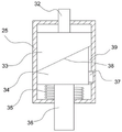
FIG. 5 is a schematic structural view of a punching mechanism according to the present invention;
fig. 6 is a schematic structural view of a punch block in the present invention.
In the figure: 1. a fixed base; 2. supporting legs; 3. a guide rail bracket; 4. a guide post; 5. moving the plate; 6. a clamping rod a; 7. a clamping block; 8. a pulley block; 9. a guide frame; 10. a lead screw; 11. moving the drum; 12. a clamping rod b; 13. a telescopic cylinder; 14. a support frame; 15. a stamping motor; 16. a fixed cylinder; 17. a belt wheel a; 18. a belt a; 19. a pulley b; 20. a connecting rod rest a; 21. a pulley c; 22. a connecting rod rest b; 23. a belt b; 24. a pulley d; 25. punching the cylinder; 26. a guide rail groove; 27. an intermediate shaft; 28. a fixing plate; 29. a slider; 30. a double-shaft motor; 31. a rotating shaft; 32. a rotating shaft; 33. rotating the block; 34. stamping the blocks; 35. stamping a spring; 36. punching the column; 37. a limiting block; 38. an oblique cross section; 39. a limiting groove.
Detailed Description
It should be noted that the embodiments and features of the embodiments may be combined with each other without conflict.
In the description of the present invention, it is to be understood that the terms "center", "longitudinal", "lateral", "upper", "lower", "front", "rear", "left", "right", "vertical", "horizontal", "top", "bottom", "inner", "outer", etc., indicate orientations or positional relationships based on those shown in the drawings, and are used only for convenience in describing and simplifying the description, but do not indicate or imply that the devices or elements referred to must have a particular orientation, be constructed and operated in a particular orientation, and therefore are not to be construed as limiting the invention, and further, the terms "first", "second", etc., are used only for descriptive purposes and are not intended to indicate or imply relative importance or to implicitly indicate the number of technical features indicated, whereby the features defined as "first", "second", etc., may explicitly or implicitly include one or more of such features, in the description of the present invention, "a plurality" means two or more unless otherwise specified.
In the description of the present invention, it should be noted that, unless otherwise explicitly specified or limited, the terms "mounted," "connected," and "connected" are to be construed broadly, e.g., as meaning either a fixed connection, a removable connection, or an integral connection; can be mechanically or electrically connected; the two elements may be directly connected or indirectly connected through an intermediate medium, and the two elements may be communicated with each other, and the specific meaning of the above terms in the present invention will be understood by those skilled in the art through specific situations.
The present invention will be described in detail below with reference to the embodiments with reference to the attached drawings.
Example 1
Referring to fig. 1 to 6, in the embodiment of the invention, a stamping tool for motor processing comprises a fixed base 1, wherein a telescopic cylinder 13 is fixedly installed on the rear side of the upper end of the fixed base 1, a support frame 14 is installed on the output end of the telescopic cylinder 13, the telescopic cylinder 13 adopts a cylinder or hydraulic cylinder structure, the up-and-down height of the support frame 14 is finally adjusted, a diameter-changing mechanism is installed on the support frame 14, a stamping mechanism is installed on the output end of the diameter-changing mechanism, the stamping mechanism can be stamped on any position of the horizontal plane of a motor part by arranging the diameter-changing mechanism, guide rail frames 3 are symmetrically and fixedly installed on two sides of the upper end of the fixed base 1, guide rail grooves 26 are arranged in the guide rail frames 3, guide pillars 4 are arranged on the guide rail frames 3 in a sliding manner, clamping mechanisms are arranged on the guide pillars 4, and in order to better ensure the stable precision of the clamping mechanisms during horizontal movement, the guide rail groove 26 is of a dovetail groove structure, a trapezoid block structure is arranged on the guide post 4, and a power mechanism for horizontally driving the two clamping mechanisms is further arranged on the bottom of the fixed base 1, so that the horizontal position between the two clamping mechanisms can be adjusted, and finally, the effective clamping and fixing effect on the motor part to be processed is realized.
In one aspect of this embodiment, reducing mechanism is including fixing the fixed section of thick bamboo 16 on support frame 14, and articulated on the fixed section of thick bamboo 16 is installed connecting rod frame a20, and it has connecting rod frame b22 to articulate on connecting rod frame a20, reducing mechanism still includes the drive assembly who is used for driving the punching press mechanism and carries out the motion, through the restriction between connecting rod frame a20 and the connecting rod frame b22 for punching press mechanism has not influenced punching press mechanism's self work when the position is moved and is adjusted on the level, has further improved the reliability of device.
In one aspect of the present embodiment, the driving assembly includes a pulley a17 vertically rotatably disposed on the fixed cylinder 16, a pulley b19 is connected to the outer side of the pulley a17 through a belt a18, an intermediate shaft 27 is fixedly mounted on the pulley b19, the intermediate shaft 27 passes through a hinge joint between the link frame a20 and the link frame b22 to be mounted with a pulley c21, and a pulley d24 is connected to the outer side of the pulley c21 through a belt b 23.
In one aspect of this embodiment, the punching mechanism includes a punching cylinder 25 fixed on the rod rest b22, a rotary block 33 is rotatably mounted inside the punching cylinder 25, the lower side of the rotary block 33 contacts with the punching block 34 through an oblique section 38, a limiting portion is disposed outside the punching block 34, so that the rotary motion of the rotary block 33 can be effectively converted into the vertical linear motion of the punching block 34, a punching column 36 is mounted at the bottom of the punching block 34, the bottom of the punching column 36 penetrates through the punching cylinder 25 to be connected with a detaching block, different types of punching parts are mounted on the detaching block, a punching spring 35 is sleeved outside the punching column 36 between the punching block 34 and the bottom side of the inner wall of the punching cylinder 25, specifically, in operation, the rotary block 33 rotates, and then under the action of the oblique section 38 and the limiting portion, the punching block 34 can reciprocate up and down under the action of the punching spring 35, finally, the stamping part can effectively stamp the motor component.
In one aspect of this embodiment, the rotating shaft 32 is fixedly mounted on the upper side of the rotating block 33, and the upper end of the rotating shaft 32 is connected to the pulley d24 through the connecting rod bracket b22, so that the torque of the driving assembly can be effectively transmitted to the punching mechanism, and the reliability of the device is further ensured.
In one aspect of this embodiment, the limiting portion includes a limiting block 37 fixed on the inner wall of the punching cylinder 25 and a limiting groove 39 disposed outside the punching block 34, the limiting block 37 is slidably disposed in the limiting groove 39, the limiting block 37 is fixedly mounted on the inner wall of the punching cylinder 25, and by setting the limiting function between the limiting groove 39 and the limiting block 37, the punching block 34 does not rotate and only can move up and down.
In one aspect of this embodiment, the support frame 14 is provided with a stamping motor 15, and the output end of the stamping motor 15 is connected with a belt wheel a17, so as to realize effective operation of the whole stamping mechanism.
In one aspect of this embodiment, the clamping mechanism includes a moving plate 5 fixed on the guide post 4, two ends of the moving plate 5 are respectively hinged with a clamping rod a6, the moving plate 5 is symmetrically provided with a fixed plate 28, a sliding block 29 is slidably provided between the fixed plates 28, a clamping rod b12 is symmetrically hinged on the sliding block 29, clamping blocks 7 are respectively hinged between clamping rods b12 on different sliding blocks 29 and between clamping rod b12 and clamping rod a6, and by setting the above technical components, the clamping blocks 7 do not directly collide rigidly when clamping the motor component, so that the motor component can be clamped more stably, and stability in the clamping device is further ensured.
In the condition of this embodiment, power unit is including fixing the double-shaft motor 30 in unable adjustment base 1 bottom, and the both sides output of double-shaft motor 30 is connected with axis of rotation 31, and axis of rotation 31 both sides are installed lead screw 10 through taking wheelset 8 respectively, and lead screw 10 installs through helicitic texture and fixes and move a section of thick bamboo 11 on movable plate 5, lead screw 10 rotates and sets up on fixing leading truck 9 on unable adjustment base 1, and is specific, when double-shaft motor 30 started, it carries out synchronous rotation to have driven lead screw 10, finally turns into the horizontal linear motion who moves a section of thick bamboo 11, finally for having realized the change of distance between grip block 7 to it is fixed to motor element's centre gripping has been ensured.
Example 2
In another embodiment of the present invention, the embodiment is different from the above embodiments in that, the four corners of the bottom of the fixing base 1 are fixedly provided with the supporting legs 2 for achieving the purpose of effectively supporting the whole stamping tool.
The working principle of the invention is as follows: the during operation, the motor element that will carry out processing is placed on unable adjustment base 1 and is located between the fixture, later double-shaft motor 30 has been started, make fixture work, it is fixed to the above-mentioned effective centre gripping to motor element has been realized, later change the stamping workpiece that corresponds the punching a hole, then adjust the upper and lower height of punching press mechanism through telescoping cylinder 13, later drive punching press motor 15, make punching press mechanism work, the effective punching press effect to motor element has been realized, when the position of punching press is adjusted to needs, then through the angle of adjusting reducing mechanism, then can satisfy the punching press needs of different positions, whole operation is swift convenient, be worth using widely.
The above description is only for the purpose of illustrating the preferred embodiments of the present invention and is not to be construed as limiting the invention, and any modifications, equivalents, improvements and the like that fall within the spirit and principle of the present invention are intended to be included therein.
Claims (8)
1. A stamping tool for motor machining comprises a fixed base (1) and is characterized in that a telescopic cylinder (13) is fixedly mounted on the rear side of the upper end of the fixed base (1), a support frame (14) is mounted at the output end of the telescopic cylinder (13), a reducing mechanism is mounted on the support frame (14), a stamping mechanism is mounted at the output end of the reducing mechanism, guide rail frames (3) are symmetrically and fixedly mounted on two sides of the upper end of the fixed base (1), a guide rail groove (26) is formed in each guide rail frame (3), a guide pillar (4) is slidably arranged on each guide rail frame (3), a clamping mechanism is arranged on each guide pillar (4), and a power mechanism for horizontally driving the two clamping mechanisms is further arranged on the bottom of the fixed base (1);
the reducing mechanism comprises a fixed cylinder (16) fixed on a support frame (14), a connecting rod frame a (20) is hinged to the fixed cylinder (16), a connecting rod frame b (22) is hinged to the connecting rod frame a (20), and the reducing mechanism further comprises a driving assembly used for driving the punching mechanism to move;
the driving assembly comprises a belt wheel a (17) vertically and rotatably arranged on a fixed cylinder (16), the outer side of the belt wheel a (17) is connected with a belt wheel b (19) through a belt a (18), an intermediate shaft (27) is fixedly mounted on the belt wheel b (19), the intermediate shaft (27) penetrates through a hinged position between a connecting rod frame a (20) and a connecting rod frame b (22) to be mounted with a belt wheel c (21), and the outer side of the belt wheel c (21) is connected with a belt wheel d (24) through a belt b (23).
2. The punching tool for motor machining according to claim 1, wherein the punching mechanism comprises a punching barrel (25) fixed to the connecting rod rest b (22), a rotating block (33) is rotatably mounted inside the punching barrel (25), a punching block (34) is in contact with the lower side of the rotating block (33) through an inclined cross section (38), a limiting portion is arranged on the outer side of the punching block (34), a punching column (36) is mounted at the bottom of the punching block (34), the bottom of the punching column (36) penetrates through the punching barrel (25) to be connected with a disassembling block, different types of punching parts are mounted on the disassembling block, and a punching spring (35) is sleeved on the outer side of the punching column (36) between the punching block (34) and the bottom side of the inner wall of the punching barrel (25).
3. The punching tool for machining the motor according to claim 2, wherein a rotating shaft (32) is fixedly mounted on the upper side of the rotating block (33), and a belt wheel d (24) is connected to the upper end of the rotating shaft (32) through a connecting rod frame b (22).
4. The stamping tool for machining the motor according to claim 2, wherein the limiting portion comprises a limiting block (37) fixed on the inner wall of the stamping cylinder (25) and a limiting groove (39) arranged on the outer side of the stamping block (34), and the limiting block (37) is slidably arranged in the limiting groove (39).
5. The punching tool for motor machining according to claim 1, wherein the support frame (14) is provided with a punching motor (15), and an output end of the punching motor (15) is connected with a belt wheel a (17).
6. The punching tool for motor machining according to claim 1, wherein the clamping mechanism comprises a moving plate (5) fixed on the guide post (4), clamping rods a (6) are hinged to two ends of the moving plate (5) respectively, fixed plates (28) are symmetrically mounted on the moving plate (5), sliding blocks (29) are arranged between the fixed plates (28) in a sliding mode, clamping rods b (12) are hinged to the sliding blocks (29) symmetrically, and clamping blocks (7) are hinged between the clamping rods b (12) on different sliding blocks (29) and between the clamping rods b (12) and the clamping rods a (6) respectively.
7. The punching tool for machining the motor according to claim 6, wherein the power mechanism comprises a double-shaft motor (30) fixed to the bottom of the fixed base (1), output ends of two sides of the double-shaft motor (30) are connected with rotating shafts (31), lead screws (10) are respectively installed on two sides of each rotating shaft (31) through belt wheel sets (8), the lead screws (10) are installed on moving cylinders (11) fixed on the moving plate (5) through threaded structures, and the lead screws (10) are rotatably arranged on guide frames (9) fixed to the fixed base (1).
8. The stamping tool for machining the motor according to claim 1, wherein the four corners of the bottom of the fixed base (1) are fixedly provided with supporting legs (2).
Priority Applications (1)
| Application Number | Priority Date | Filing Date | Title |
|---|---|---|---|
| CN202210997661.0A CN115069863A (en) | 2022-08-19 | 2022-08-19 | Stamping tool for motor machining |
Applications Claiming Priority (1)
| Application Number | Priority Date | Filing Date | Title |
|---|---|---|---|
| CN202210997661.0A CN115069863A (en) | 2022-08-19 | 2022-08-19 | Stamping tool for motor machining |
Publications (1)
| Publication Number | Publication Date |
|---|---|
| CN115069863A true CN115069863A (en) | 2022-09-20 |
Family
ID=83245102
Family Applications (1)
| Application Number | Title | Priority Date | Filing Date |
|---|---|---|---|
| CN202210997661.0A Pending CN115069863A (en) | 2022-08-19 | 2022-08-19 | Stamping tool for motor machining |
Country Status (1)
| Country | Link |
|---|---|
| CN (1) | CN115069863A (en) |
Cited By (1)
| Publication number | Priority date | Publication date | Assignee | Title |
|---|---|---|---|---|
| CN117020023A (en) * | 2023-10-09 | 2023-11-10 | 山东中航泰达复合材料有限公司 | Composite material bending forming die |
Citations (7)
| Publication number | Priority date | Publication date | Assignee | Title |
|---|---|---|---|---|
| KR20040006097A (en) * | 2002-07-09 | 2004-01-24 | 현대자동차주식회사 | Piercing device for press system |
| CN107297521A (en) * | 2017-07-14 | 2017-10-27 | 合肥雷呈信息技术有限公司 | A kind of stable drilling equipment for main frame box structure |
| CN108889797A (en) * | 2018-09-26 | 2018-11-27 | 温州盛瓯机电信息技术有限公司 | A kind of clamping device of section-straightening machine |
| CN209124667U (en) * | 2018-11-15 | 2019-07-19 | 江苏感恩机械有限公司 | Stamping equipment is used in a kind of processing of automobile parts |
| CN110480049A (en) * | 2019-09-17 | 2019-11-22 | 潘丽 | A kind of drilling robot moving back bits automatically |
| CN216680291U (en) * | 2021-07-12 | 2022-06-07 | 蚌埠兴力传感系统工程有限公司 | Punching device for sensor production |
| CN114700431A (en) * | 2022-03-25 | 2022-07-05 | 盐城泓盈汽车零部件有限公司 | Stamping device for automobile parts and using method thereof |
-
2022
- 2022-08-19 CN CN202210997661.0A patent/CN115069863A/en active Pending
Patent Citations (7)
| Publication number | Priority date | Publication date | Assignee | Title |
|---|---|---|---|---|
| KR20040006097A (en) * | 2002-07-09 | 2004-01-24 | 현대자동차주식회사 | Piercing device for press system |
| CN107297521A (en) * | 2017-07-14 | 2017-10-27 | 合肥雷呈信息技术有限公司 | A kind of stable drilling equipment for main frame box structure |
| CN108889797A (en) * | 2018-09-26 | 2018-11-27 | 温州盛瓯机电信息技术有限公司 | A kind of clamping device of section-straightening machine |
| CN209124667U (en) * | 2018-11-15 | 2019-07-19 | 江苏感恩机械有限公司 | Stamping equipment is used in a kind of processing of automobile parts |
| CN110480049A (en) * | 2019-09-17 | 2019-11-22 | 潘丽 | A kind of drilling robot moving back bits automatically |
| CN216680291U (en) * | 2021-07-12 | 2022-06-07 | 蚌埠兴力传感系统工程有限公司 | Punching device for sensor production |
| CN114700431A (en) * | 2022-03-25 | 2022-07-05 | 盐城泓盈汽车零部件有限公司 | Stamping device for automobile parts and using method thereof |
Cited By (1)
| Publication number | Priority date | Publication date | Assignee | Title |
|---|---|---|---|---|
| CN117020023A (en) * | 2023-10-09 | 2023-11-10 | 山东中航泰达复合材料有限公司 | Composite material bending forming die |
Similar Documents
| Publication | Publication Date | Title |
|---|---|---|
| CN111299367A (en) | Flexible intelligent bending equipment for bending metal plate | |
| CN114951403B (en) | Stamping equipment is used in auto-parts processing | |
| CN115069863A (en) | Stamping tool for motor machining | |
| CN210820079U (en) | Concrete member forming machine | |
| CN113976724A (en) | Plate punching device for new energy automobile machining | |
| CN213380177U (en) | Press machine capable of simultaneously performing multi-surface stamping and adjusting force application angle | |
| CN216679753U (en) | Numerical control punch capable of preventing plate from deforming | |
| CN211539225U (en) | Stamping die of refrigerator sheet metal part | |
| CN212216761U (en) | Punching device for production and processing of three-phase asynchronous motor | |
| CN114346041A (en) | Stamping device and stamping method for plate processing | |
| CN211304490U (en) | Clamp matched with stamping die | |
| CN219074266U (en) | Riveting press for sheet metal machining | |
| CN218556762U (en) | Clamping tool for machining cylinder mounting plate | |
| CN214137438U (en) | Two-column press with swing arm punch | |
| CN220178009U (en) | Punch press limit clamp for hardware processing | |
| CN217289989U (en) | Automobile end cover stamping die capable of improving stress uniformity of finished products | |
| CN220658920U (en) | Punching machine is used in cycloid speed reducer production | |
| CN220161028U (en) | Punch press that loudspeaker cone was used | |
| CN213288236U (en) | Bending machine with fixing device | |
| CN219851572U (en) | Auxiliary punching device for aluminum products | |
| CN217192139U (en) | Fixed fixture of servo punch press | |
| CN112792159B (en) | Be used for trying to make two side plastic frocks of high-strength steel beam class spare | |
| CN217315439U (en) | Mechanical stamping die convenient to adjust | |
| CN220049625U (en) | Continuous stamping die convenient to adjust metalwork processing angle | |
| CN219309709U (en) | Multi-station forming machine for aluminum bottles |
Legal Events
| Date | Code | Title | Description |
|---|---|---|---|
| PB01 | Publication | ||
| PB01 | Publication | ||
| SE01 | Entry into force of request for substantive examination | ||
| SE01 | Entry into force of request for substantive examination | ||
| RJ01 | Rejection of invention patent application after publication | ||
| RJ01 | Rejection of invention patent application after publication |
Application publication date: 20220920 |