CN115055877A - Ultra-large herringbone gate hinge welding rack - Google Patents
Ultra-large herringbone gate hinge welding rack Download PDFInfo
- Publication number
- CN115055877A CN115055877A CN202210703085.4A CN202210703085A CN115055877A CN 115055877 A CN115055877 A CN 115055877A CN 202210703085 A CN202210703085 A CN 202210703085A CN 115055877 A CN115055877 A CN 115055877A
- Authority
- CN
- China
- Prior art keywords
- hinge
- welding
- image
- gate
- ultra
- Prior art date
- Legal status (The legal status is an assumption and is not a legal conclusion. Google has not performed a legal analysis and makes no representation as to the accuracy of the status listed.)
- Pending
Links
Images


Classifications
-
- B—PERFORMING OPERATIONS; TRANSPORTING
- B23—MACHINE TOOLS; METAL-WORKING NOT OTHERWISE PROVIDED FOR
- B23K—SOLDERING OR UNSOLDERING; WELDING; CLADDING OR PLATING BY SOLDERING OR WELDING; CUTTING BY APPLYING HEAT LOCALLY, e.g. FLAME CUTTING; WORKING BY LASER BEAM
- B23K37/00—Auxiliary devices or processes, not specially adapted to a procedure covered by only one of the preceding main groups
- B23K37/04—Auxiliary devices or processes, not specially adapted to a procedure covered by only one of the preceding main groups for holding or positioning work
- B23K37/0461—Welding tables
-
- B—PERFORMING OPERATIONS; TRANSPORTING
- B08—CLEANING
- B08B—CLEANING IN GENERAL; PREVENTION OF FOULING IN GENERAL
- B08B15/00—Preventing escape of dirt or fumes from the area where they are produced; Collecting or removing dirt or fumes from that area
- B08B15/04—Preventing escape of dirt or fumes from the area where they are produced; Collecting or removing dirt or fumes from that area from a small area, e.g. a tool
-
- B—PERFORMING OPERATIONS; TRANSPORTING
- B23—MACHINE TOOLS; METAL-WORKING NOT OTHERWISE PROVIDED FOR
- B23K—SOLDERING OR UNSOLDERING; WELDING; CLADDING OR PLATING BY SOLDERING OR WELDING; CUTTING BY APPLYING HEAT LOCALLY, e.g. FLAME CUTTING; WORKING BY LASER BEAM
- B23K37/00—Auxiliary devices or processes, not specially adapted to a procedure covered by only one of the preceding main groups
- B23K37/02—Carriages for supporting the welding or cutting element
- B23K37/0252—Steering means
-
- B—PERFORMING OPERATIONS; TRANSPORTING
- B25—HAND TOOLS; PORTABLE POWER-DRIVEN TOOLS; MANIPULATORS
- B25J—MANIPULATORS; CHAMBERS PROVIDED WITH MANIPULATION DEVICES
- B25J9/00—Programme-controlled manipulators
- B25J9/16—Programme controls
- B25J9/1602—Programme controls characterised by the control system, structure, architecture
-
- B—PERFORMING OPERATIONS; TRANSPORTING
- B25—HAND TOOLS; PORTABLE POWER-DRIVEN TOOLS; MANIPULATORS
- B25J—MANIPULATORS; CHAMBERS PROVIDED WITH MANIPULATION DEVICES
- B25J9/00—Programme-controlled manipulators
- B25J9/16—Programme controls
- B25J9/1656—Programme controls characterised by programming, planning systems for manipulators
-
- B—PERFORMING OPERATIONS; TRANSPORTING
- B25—HAND TOOLS; PORTABLE POWER-DRIVEN TOOLS; MANIPULATORS
- B25J—MANIPULATORS; CHAMBERS PROVIDED WITH MANIPULATION DEVICES
- B25J9/00—Programme-controlled manipulators
- B25J9/16—Programme controls
- B25J9/1694—Programme controls characterised by use of sensors other than normal servo-feedback from position, speed or acceleration sensors, perception control, multi-sensor controlled systems, sensor fusion
- B25J9/1697—Vision controlled systems
Abstract
The invention discloses an ultra-large type herringbone gate hinge welding machine frame which comprises a fixing bottom plate, a hydraulic jack, an industrial personal computer, a reinforcing cross beam, a frame, a roll shaft, a gate fixing device, a welding device, a smoke dust collecting system, a hinge fixing device and an image capturing device. The image of the hinge to be welded is acquired through the image capturing device, the image of the hinge is transmitted to the industrial personal computer for processing, finally, the welding path obtained through processing is converted into the operation instruction of the welding device, and the welding device finishes the welding process. The hinge welding of the remote control refined ultra-large herringbone gate is realized. The gate fixing device and the hinge fixing device are used for clamping the gate plate and the hinge to complete welding, so that the welding position of the gate plate and the hinge is controlled, and the problems that products are deformed by heating during welding, and quality defects such as size deviation and product deformation frequently occur are solved. The height of the frame can be changed by adjusting the hydraulic jack downwards, and different use requirements can be met.
Description
Technical Field
The invention relates to the technical field of welding, in particular to an ultra-large herringbone gate hinge welding rack.
Background
The ultra-large type miter gate is a gate which is opened and closed by rotating a left gate leaf and a right gate leaf around a gate shaft column at two sides respectively. When the door is closed, the two door leaves are in a herringbone shape and are mutually contacted by oblique connecting columns to form a three-hinge arch to bear water pressure. When the door is opened, the door leaves enter the niche of the gate head. At present, a welding process is needed to be adopted in the processing and manufacturing of the ultra-large herringbone gate hinge. Welding is a manufacturing technique for permanently connecting materials, is one of the most important industrial techniques in the manufacturing industry, and the quality of welding also directly affects the quality and reliability of products. The general intensity of labour of welding operation is great, and operational environment is abominable, and the welding shop mainly pollutes and has: welding fume, harmful gases, noise, high-frequency electromagnetic radiation and light pollution. The existing protection measures can only prevent pollution on one aspect and can not completely isolate all pollution in a welding workshop. In hot summer, welders also need to wear thick protective clothing in order to prevent spark burns caused by welding. In order to keep workers healthy and improve welding production efficiency, the welding workload is large in the production process, and machine welding is necessary to replace manual welding. The traditional automatic welding method of the machine adopts a teaching mode, each welding part needs a set of special teaching program, teaching operation needs experienced technical workers, time consumption is long, once the position of the welding part is changed a bit, teaching needs to be carried out again, otherwise wrong welding and welding missing can occur very well, and welding quality is unqualified directly. The existing gate hinge is welded by adopting marking and positioning welding, so that the size cannot be guaranteed, welding missing, welding inclination and welding missing are frequently caused, and the qualified rate is low. In addition, during welding, products are easy to deform due to the fact that the gate hinges are arranged, and quality defects such as size deviation and product deformation often occur, so that welding quality is unstable, and welding efficiency is low. At last current welding frame, the workstation is mostly fixed the setting, in case the installation, just inconvenient height-adjusting can not satisfy different user demands, and is more troublesome during the material loading.
Disclosure of Invention
The invention aims to provide an ultra-large type herringbone gate hinge welding machine frame to solve the problems in the background technology.
In order to achieve the purpose, the invention provides the following technical scheme: the utility model provides an ultra-large herringbone gate hinge welding frame, includes PMKD fixedly connected with hydraulic jack all around of PMKD, the PMC is equipped with on the PMC, be equipped with between the hydraulic jack and connect the reinforcement crossbeam, the upper end fixedly connected with frame of hydraulic jack, rotate between the frame and connect a plurality of roller, both ends are equipped with the gate fixing device that is parallel relatively about the frame, the other end of frame is fixed with smoke and dust collecting system and hinge fixing device, fixedly connected with welding set on the PMC of hinge fixing device homonymy, the last image capture device that is equipped with of welding set, hydraulic jack, gate fixing device, welding set, image capture device, smoke and dust collecting system and hinge fixing device all carry out communication connection with the PMC, gate fixing device includes door body locating plate, door body locating plate, The welding device comprises a track, a rotating disc, a base column, a first mechanical arm, a second mechanical arm and a welding gun head, wherein the rotating disc horizontally slides on the track through a servo motor, the base column is fixedly connected to the rotating disc, the top end of the base column is rotatably connected with one end of the first mechanical arm, the other end of the first mechanical arm is rotatably connected with one end of the second mechanical arm, the other end of the second mechanical arm is provided with a welding gun head, the smoke dust collecting system comprises a dust suction port, an air pipe, a negative pressure device and a purifier, the dust suction port is fixedly connected to the frame, the dust suction port is connected with the negative pressure device and the purifier through the air pipe, the hinge fixing device comprises a second electric telescopic rod, a hinge pressing plate, a hinge baffle plate and a second hydraulic cylinder, one end of the second hydraulic cylinder is fixedly connected with the hinge baffle plate, the lower portion of the hinge baffle plate is fixedly connected with the second electric telescopic rod, the lower end of the second electric telescopic rod is fixedly connected with the hinge pressing plate, the hinge pressing plate vertically slides below the door body positioning plate through the second electric telescopic rod, and the image capturing device is used for collecting images of a miter gate door body and a hinge welding area in the welding process and transmitting the images to an industrial personal computer for welding.
Preferably, the fixed bottom plate is a steel plate, and the thickness of the fixed bottom plate is greater than 30 cm.
Preferably, the number of the hydraulic jacks is at least 6.
Preferably, a reinforcing rib is arranged at the joint of the hydraulic jack and the frame.
Preferably, the lower surfaces of the pressure plate and the hinge pressure plate are made of anti-skid materials.
Preferably, a protective cover is arranged on the outer surface of the dust suction opening.
Preferably, the image capturing device is composed of an industrial camera, an industrial lens, and an illumination device.
Preferably, the lower part of the fixed bottom plate is fixedly connected with a ground foot.
Preferably, the industrial personal computer is used for: acquiring a welding image acquired by an image capturing device, carrying out hinge image denoising, calculating a gradient vector or a normal vector of a corresponding point in the image by using a Sobel operator so as to obtain a first-order gradient of the digital image, carrying out plane convolution on two groups of matrixes which respectively represent the transverse direction and the longitudinal direction of the image and the image so as to obtain transverse direction and longitudinal direction difference approximate values of the image, calculating the gradient size by using the following formula according to the transverse direction and longitudinal direction gradient approximate values of each pixel of the image,
calculating formula of gradient direction

Where Gx and Gy denote the images after the horizontal and vertical edge detection, respectively,
obtaining an image edge in this way; and then denoising by using a contour point perimeter method, wherein the contour consists of a series of points, the image has two contours, namely a hinge contour and a noise point contour, only one hinge contour is provided, the noise point contour is numerous, the number of points contained in the hinge contour is the largest, according to the characteristic, one contour containing the largest number of points is screened from all contours in the image, the hinge contour is obtained, and other noise point contours are deleted, so that the image denoising is realized.
Preferably, the industrial personal computer is further configured to: the method comprises the steps of obtaining a welding image collected by an image capturing device to extract the edge of a hinge weld, detecting straight lines in the hinge image in a Hough transform mode, and screening three Hough straight lines with slopes close to zero edges from all the detected Hough straight lines to be the hinge weld.
Compared with the prior art, the invention has the beneficial effects that: an image of a hinge to be welded is acquired through an image capturing device, the image of the hinge is transmitted to a corresponding program on an industrial personal computer for processing, finally, a welding path obtained through processing is converted into an operation instruction of a welding device, and the welding device finishes a welding process. The hinge welding of the refined ultra-large type miter gate of the remote control is realized, and the hinge of the ultra-large type miter gate can be welded intelligently. The problem of current extra-large-size miter gate door body in the production process welding work load big, rely on artifical the completion welding and influenced work efficiency is solved, the healthy safety of effective protection workman.
The gate plate and the hinge are clamped by the gate fixing device and the hinge fixing device to complete welding, so that the welding position of the gate plate and the hinge is controlled, and the problems of dimensional deviation, product deformation and other quality defects caused by thermal deformation of a product during welding are solved. Not only improves the welding processing efficiency, but also can ensure the reliability and consistency of the welding processing.
Through the smoke dust collecting system, smoke dust enters the purifier from the dust suction port through the air pipe when the hinge is welded. Can in time absorb impurity such as cigarette, dust that welding set produced in the course of the work, improve the operational environment in production place, can effectual solution smoke and dust, gas pollution problem.
The height of the frame can be changed by adjusting the hydraulic jack downwards, so that the height can be adjusted, and different use requirements can be met. The ultra-large herringbone gate door plate can be conveniently moved to a working position through the roller shaft, and the use is convenient.
Drawings
FIG. 1 is a front view of the present invention;
FIG. 2 is a side view of the present invention;
FIG. 3 is a top view of the present invention;
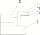
FIG. 4 is a schematic structural view of a gate fixing device according to the present invention;
FIG. 5 is a schematic view of the welding apparatus of the present invention;
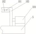
FIG. 6 is a schematic view of the hinge fixing device of the present invention;
FIG. 7 is a flow chart of the industrial personal computer image processing of the present invention; .
In the figure: 1. the device comprises a fixed bottom plate, 2 hydraulic jacks, 3 industrial personal computers, 4 reinforcing cross beams, 5 frames, 6 roller shafts, 7 gate fixing devices, 8 welding devices, 9 smoke dust collecting systems, 10 hinge fixing devices, 11 image capturing devices, 12 reinforcing ribs, 13 ground feet, 71 door body positioning plates, 72 first hydraulic cylinders, 73 first electric telescopic rods, 74 pressing plates, 81 tracks, 82 rotating discs, 83 foundation columns, 84 first mechanical arms, 85 second mechanical arms, 86 welding gun heads, 91 dust suction ports, 92 air pipes, 93 negative pressure devices, 94 purifiers, 95 protective covers, 101 second electric telescopic rods, 102 hinge pressing plates, 103 hinge baffles and 104 second hydraulic cylinders.
Detailed Description
The technical solutions in the embodiments of the present invention will be clearly and completely described below with reference to the drawings in the embodiments of the present invention, and it is obvious that the described embodiments are only a part of the embodiments of the present invention, and not all of the embodiments. All other embodiments, which can be derived by a person skilled in the art from the embodiments given herein without making any creative effort, shall fall within the protection scope of the present invention.
Spatially relative terms, such as "above … …," "above … …," "above … …," "above," and the like, may be used herein for ease of description to describe one device or feature's spatial relationship to another device or feature as illustrated in the figures. It will be understood that the spatially relative terms are intended to encompass different orientations of the device in use or operation in addition to the orientation depicted in the figures. For example, if a device in the figures is turned over, devices described as "above" or "on" other devices or configurations would then be oriented "below" or "under" the other devices or configurations. Thus, the exemplary term "above … …" can include both an orientation of "above … …" and "below … …". The device may be otherwise variously oriented (rotated 90 degrees or at other orientations) and the spatially relative descriptors used herein interpreted accordingly.
Exemplary embodiments according to the present application will now be described in more detail with reference to the accompanying drawings. These exemplary embodiments may, however, be embodied in many different forms and should not be construed as limited to only the embodiments set forth herein. It is to be understood that these embodiments are provided so that this disclosure will be thorough and complete, and will fully convey the concept of the exemplary embodiments to those skilled in the art, in the drawings, the thicknesses of layers and regions are exaggerated for clarity, and the same devices are denoted by the same reference numerals, and thus the description thereof will be omitted.
Referring to fig. 1 to 6, a technical solution provided by the embodiment of the present invention is: the utility model provides a super large-scale mitre gate hinge welding frame, includes PMKD 1, PMKD 1's fixedly connected with hydraulic jack 2 all around, through the 5 height of hydraulic jack 2 adjustment frame, the height that can change the frame is adjusted to the adjustment, and the user demand that can satisfy the difference is adjusted in the height of adjusting. The industrial personal computer 3 is arranged on the fixing bottom plate 1, the connecting and reinforcing cross beam 4 is arranged between the hydraulic jacks 2, a frame 5 is fixedly connected to the upper ends of the hydraulic jacks 2, the frame 5 is rotatably connected with a plurality of roller shafts 6, the ultra-large herringbone gate door panels can be conveniently moved to a working position through the roller shafts 6, the ultra-large herringbone gate door panels are convenient to use, the gate fixing devices 7 which are parallel relatively are arranged at the left end and the right end of the frame 5, the smoke collecting system 9 and the hinge fixing device 10 are fixed to the other end of the frame 5, the gate door panels and the hinges are clamped tightly through the gate fixing device 7 and the hinge fixing device 10 to complete welding, the control over the welding positions of the gate door panels and the hinges is realized, and the problems that products are deformed when being welded, size deviation, product deformation and other quality defects are frequently caused are solved. The welding device 8 is fixedly connected to the fixing bottom plate 1 on the same side of the hinge fixing device 10, the image capturing device 11 is arranged on the welding device 8, the hydraulic jack 2, the gate fixing device 7, the welding device 8, the image capturing device 11, the smoke dust collecting system 9 and the hinge fixing device 10 are all in communication connection with the industrial personal computer 3, the gate fixing device 7 comprises a door body positioning plate 71, a first hydraulic cylinder 72, a first electric telescopic rod 73 and a pressing plate 74, the first hydraulic cylinder 72 is fixedly connected to the frame 5, the top end of the first hydraulic cylinder 72 is fixedly connected with the door body positioning plate 71, the first hydraulic cylinder 72 drives the door body positioning plate 71 to horizontally slide, the lower part of the door body positioning plate 71 is fixedly connected with the first electric telescopic rod 73, the lower end of the first electric telescopic rod 73 is fixedly connected with the pressure plate 74, the pressure plate 74 vertically slides below the door body positioning plate 71 through the first electric telescopic rod 73, the welding device 8 comprises a track 81, a rotating disc 82, a base column 83, a first mechanical arm 84, a second mechanical arm 85 and a welding gun head 86, the rotating disc 82 horizontally slides on the track 81 through a servo motor, the base column 83 is fixedly connected to the rotating disc 82, the top end of the base column 83 is rotatably connected with one end of the first mechanical arm 84, the other end of the first mechanical arm 84 is rotatably connected with one end of the second mechanical arm 85, the other end of the second mechanical arm 85 is provided with the welding gun head 86, the smoke dust collecting system 9 comprises a dust suction port 91, an air pipe 92, a negative pressure device 93 and a purifier 94, the dust suction port 91 is fixedly connected to the frame 5, the dust suction port 91 is connected with the negative pressure device 93 and the purifier 94 through the air pipe 92, with the fume collection system 9, fume enters the scrubber 94 through the duct 92 from the suction opening 91 when the hinge is welded. The hinge fixing device 10 comprises a second electric telescopic rod 101, a hinge pressing plate 102, a hinge baffle plate 103 and a second hydraulic cylinder 104, one end of the second hydraulic cylinder 104 is fixedly connected with the hinge baffle plate 103, the lower portion of the hinge baffle plate 103 is fixedly connected with the second electric telescopic rod 101, the lower end of the second electric telescopic rod 101 is fixedly connected with the hinge pressing plate 102, the hinge pressing plate 102 vertically slides below the door body positioning plate 103 through the second electric telescopic rod 101, and the image capturing device 11 is used for collecting images of a miter gate door body and a hinge welding area in the welding process and transmitting the images to the industrial personal computer 3 for welding. The welding image collected by the image capturing device 11 is transmitted to a corresponding program on the industrial personal computer 3 for processing, finally, the welding path obtained by processing is converted into an operation instruction of the welding device, and the welding device 8 finishes the welding process. The hinge welding of the refined ultra-large type miter gate of the remote control is realized, and the hinge of the ultra-large type miter gate can be welded intelligently.
Specifically, the fixed base plate 1 is a steel plate, and the thickness of the fixed base plate 1 is larger than 30cm, so that the integral gravity center of the rack is ensured to be stable at the bottom of the rack.
In particular, the number of hydraulic jacks 2 is at least 6, and the multi-point support ensures the stability of the frame 5.
Particularly, the joint of the hydraulic jack 2 and the frame 5 is provided with a reinforcing rib 12, so that the stability and the durability of the frame are improved.
Specifically, the lower surfaces of the pressure plate 74 and the hinge pressure plate 102 are made of non-slip materials, so that the friction force is increased to better clamp the gate plate and the hinge for welding.
Specifically, the outer surface of the dust suction port 91 is provided with a protective cover 95, so that the dust suction port 91 is protected and the service life is prolonged.
Specifically, the image capturing apparatus 11 is composed of an industrial camera, an industrial lens, and an illumination apparatus.
Particularly, the lower part of the fixed bottom plate 1 is fixedly and fixedly linked with the ground feet 13, so that the integral balance of the rack can be conveniently adjusted during installation.
In this embodiment, referring to fig. 7, the image processing part of the industrial personal computer 3 is configured to perform the following steps:
in step S101, a welding image captured by the image capturing device 11 is acquired.
Step S102, using Sobel operator to calculate the image edge, using Sobel operator to calculate the gradient vector or normal vector of the corresponding point in the image, thus obtaining the first order gradient of the digital image, obtaining the horizontal and vertical difference approximate value of the image by performing plane convolution on two groups of 3X 3 matrixes which respectively represent the horizontal and vertical directions of the image and the image, calculating the gradient magnitude by the following formula for the horizontal and vertical gradient approximate value of each pixel of the image,

calculating formula of gradient direction

Where Gx and Gy denote the images after the horizontal and vertical edge detection, respectively,
obtaining an image edge in this way;
s103, denoising by using a contour point perimeter method, wherein the contour is composed of a series of points, the image has two contours, namely a hinge contour and a noise point contour, only one hinge contour is provided, the noise point contour is numerous, the number of points contained in the hinge contour is the largest, according to the characteristic, one contour containing the largest number of points is screened out from all contours in the image, the hinge contour is obtained, and then other noise point contours are deleted, so that the image denoising is realized.
And step S104, screening the hinge welding seams in a Hough transform mode. The method comprises the steps of obtaining a welding image collected by an image capturing device 11, extracting the edge of a hinge weld, detecting straight lines in the hinge image in a Hough transform mode, and screening three Hough straight lines with slopes close to zero edges from all the detected Hough straight lines to be the hinge weld.
In step S105, the coordinates of the edge of the hinge weld are converted, the coordinates in the image are the coordinates of the image, and the robot performs the processing using the coordinates of the robot, so the coordinates of the image are converted into the coordinates of the robot. Converting the image coordinate into the robot coordinate requires solving a translation matrix and a rotation matrix. Namely: and the coordinates of the robot coordinate system are the coordinates of the image coordinate system, the rotation matrix and the translation matrix. After the rotation matrix and the translation matrix are solved, for each image coordinate of the edge of the hinge welding seam, the corresponding robot coordinate can be solved. The coordinate conversion process is written by a matlab program, the coordinate matrixes are respectively obtained firstly and are input into the program, the conversion matrix is generated after calculation, and the value of the conversion matrix is input into a hinge weld joint recognition machine program written by C # language and is used for converting the obtained edge image coordinates of the hinge weld joint into the coordinates of the robot and the subsequent welding of the hinge.
The working principle is as follows: when the device is used, the hydraulic jack 2 is controlled to lift through the industrial personal computer 3, the height of the rack is changed, and feeding of the ultra-large herringbone gate is facilitated. The ultra-large herringbone gate door plate can be conveniently moved to a working position through the roller shaft 6. The first hydraulic cylinder 72 of the gate fixing device 7 drives the gate positioning plate 71 to adjust the position of the gate body, so that welding is facilitated, and the first electric telescopic rod 73 drives the pressing plate 74 to clamp the gate body. The second hydraulic cylinder 104 of the hinge fixing device 10 drives the door hinge baffle 103 to adjust the hinge position for convenient welding, and the second electric telescopic rod 101 drives the hinge pressing plate 102 to clamp the gate hinge. The control of the welding position of the gate plate and the hinge is realized, and the problems that products are heated to deform during welding, and quality defects such as size deviation and product deformation frequently occur are solved. Not only improves the welding processing efficiency, but also can ensure the reliability and consistency of the welding processing. The welding image collected by the image capturing device 11 is transmitted to a corresponding program on the industrial personal computer 3 for processing, finally, the welding path obtained by processing is converted into an operation instruction of the welding device, and the welding device 8 finishes the welding process. The hinge welding of the refined ultra-large type miter gate of the remote control is realized, and the hinge of the ultra-large type miter gate can be welded intelligently. The problem of current extra-large-size miter gate door body in the production process welding work load big, rely on artifical the completion welding and influenced work efficiency is solved, the healthy safety of effective protection workman. With the fume collection system 9, fume enters the scrubber 94 through the duct 92 from the suction opening 91 when the hinge is welded. Can in time absorb impurity such as cigarette, dust that welding set produced in the course of the work, improve the operational environment in production place, can effectual solution smoke and dust, gas pollution problem.
It should be noted that the terms "first," "second," and the like in the description and claims of this application and in the drawings described above are used for distinguishing between similar elements and not necessarily for describing a particular sequential or chronological order. It is to be understood that the data so used is interchangeable under appropriate circumstances such that the embodiments of the application described herein are, for example, capable of operation in sequences other than those illustrated or otherwise described herein.
Although embodiments of the present invention have been shown and described, it will be appreciated by those skilled in the art that changes, modifications, substitutions and alterations can be made in these embodiments without departing from the principles and spirit of the invention, the scope of which is defined in the appended claims and their equivalents.
Claims (10)
1. The utility model provides an ultra-large type mitre gate hinge welding frame, includes PMKD (1), its characterized in that: fixedly connected with hydraulic jack (2) all around of PMKD (1), be equipped with industrial computer (3) on PMKD (1), be equipped with between hydraulic jack (2) and connect reinforcement crossbeam (4), the upper end fixedly connected with frame (5) of hydraulic jack (2), rotate between frame (5) and connect a plurality of roller (6), both ends are equipped with gate fixing device (7) parallel relatively about frame (5), the other end of frame (5) is fixed with smoke and dust collecting system (9) and hinge fixing device (10), fixedly connected with welding set (8) on PMKD (1) of hinge fixing device (10) homonymy, be equipped with image capture device (11) on welding set (8), hydraulic jack (2), gate fixing device (7), welding set (8), The device comprises an image capturing device (11), a smoke dust collecting system (9) and a hinge fixing device (10) which are in communication connection with an industrial personal computer (3), wherein the gate fixing device (7) comprises a door body positioning plate (71), a first hydraulic cylinder (72), a first electric telescopic rod (73) and a pressing plate (74), the first hydraulic cylinder (72) is fixedly connected to a frame (5), the top end of the first hydraulic cylinder (72) is fixedly connected with the door body positioning plate (71), the first hydraulic cylinder (72) drives the door body positioning plate (71) to horizontally slide, the lower portion of the door body positioning plate (71) is fixedly connected with the first electric telescopic rod (73), the lower end of the first electric telescopic rod (73) is fixedly connected with the pressing plate (74), the pressing plate (74) vertically slides below the door body positioning plate (71) through the first electric telescopic rod (73), and the welding device (8) comprises a rail (81), The smoke dust collecting system comprises a rotating disc (82), a base column (83), a first mechanical arm (84), a second mechanical arm (85) and a welding gun head (86), wherein the rotating disc (82) horizontally slides on a track (81) through a servo motor, the base column (83) is fixedly connected to the rotating disc (82), the top end of the base column (83) is rotatably connected with one end of the first mechanical arm (84), the other end of the first mechanical arm (84) is rotatably connected with one end of the second mechanical arm (85), the other end of the second mechanical arm (85) is provided with the welding gun head (86), the smoke dust collecting system (9) comprises a dust suction port (91), an air pipe (92), a negative pressure device (93) and a purifier (94), the dust suction port (91) is fixedly connected to a frame (5), and the dust suction port (91) is connected with the negative pressure device (93) and the purifier (94) through the air pipe (92), the hinge fixing device (10) comprises a second electric telescopic rod (101), a hinge pressing plate (102), a hinge baffle plate (103) and a second hydraulic cylinder (104), one end of the second hydraulic cylinder (104) is fixedly connected with the hinge baffle plate (103), the lower portion of the hinge baffle plate (103) is fixedly connected with the second electric telescopic rod (101), the lower end of the second electric telescopic rod (101) is fixedly connected with the hinge pressing plate (102), the hinge pressing plate (102) vertically slides below the door body positioning plate (103) through the second electric telescopic rod (101), and the image capturing device (11) is used for collecting images of a miter gate door body and a hinge welding area in the welding process and transmitting the images to the industrial personal computer (3) for welding.
2. The ultra-large miter gate hinge welding rack according to claim 1, characterized in that: the fixed bottom plate (1) is a steel plate, and the thickness of the fixed bottom plate (1) is larger than 30 cm.
3. The ultra-large miter gate hinge welding rack according to claim 1, characterized in that: the number of the hydraulic jacks (2) is at least 6.
4. The ultra-large miter gate hinge welding rack according to claim 1, characterized in that: and reinforcing ribs (12) are arranged at the joints of the hydraulic jacks (2) and the frame (5).
5. The ultra-large miter gate hinge welding rack according to claim 1, characterized in that: the lower surfaces of the pressure plate (74) and the hinge pressure plate (102) are made of anti-skid materials.
6. The ultra-large miter gate hinge welding rack according to claim 1, characterized in that: the outer surface of the dust collection opening (91) is provided with a protective cover (95).
7. The ultra-large miter gate hinge welding rack according to claim 1, characterized in that: the image capturing device (11) is composed of an industrial camera, an industrial lens and an illumination device.
8. The ultra-large miter gate hinge welding rack according to claim 1, characterized in that: and the lower part of the fixed bottom plate (1) is fixedly and fixedly connected with a ground foot (13).
9. The ultra-large miter gate hinge welding rack according to claim 1, characterized in that: the industrial personal computer (3) is used for: acquiring a welding image acquired by an image capturing device (11), carrying out hinge image denoising, calculating a gradient vector or a normal vector of a corresponding point in the image by using a Sobel operator so as to obtain a first-order gradient of a digital image, carrying out plane convolution on two groups of matrixes which respectively represent the transverse direction and the longitudinal direction of the image and the image so as to obtain transverse direction and longitudinal direction difference approximate values of the image, calculating the gradient size by using the following formula according to the transverse direction and longitudinal direction gradient approximate values of each pixel of the image,

calculating formula of gradient direction

Where Gx and Gy denote the images after the horizontal and vertical edge detection, respectively,
obtaining the image edge by the method; and denoising by using a contour point perimeter method, wherein the contour consists of a series of points, the image has two contours, namely a hinge contour and a noise point contour, only one hinge contour is provided, the noise point contour is provided with a plurality of points, the number of the points contained in the hinge contour is the largest, according to the characteristic, one contour with the largest number of the points is screened from all the contours in the image, the hinge contour is obtained, and other noise point contours are deleted, so that the image denoising is realized.
10. The ultra-large miter gate hinge welding rack according to claim 1, characterized in that: the industrial personal computer (3) is also used for: the method comprises the steps of obtaining a welding image collected by an image capturing device (11), extracting the edge of a hinge weld, detecting straight lines in the hinge image in a Hough transform mode, and screening three Hough straight lines with slopes close to zero edges from all the detected Hough straight lines to be the hinge weld.
Priority Applications (1)
| Application Number | Priority Date | Filing Date | Title |
|---|---|---|---|
| CN202210703085.4A CN115055877A (en) | 2022-06-21 | 2022-06-21 | Ultra-large herringbone gate hinge welding rack |
Applications Claiming Priority (1)
| Application Number | Priority Date | Filing Date | Title |
|---|---|---|---|
| CN202210703085.4A CN115055877A (en) | 2022-06-21 | 2022-06-21 | Ultra-large herringbone gate hinge welding rack |
Publications (1)
| Publication Number | Publication Date |
|---|---|
| CN115055877A true CN115055877A (en) | 2022-09-16 |
Family
ID=83202866
Family Applications (1)
| Application Number | Title | Priority Date | Filing Date |
|---|---|---|---|
| CN202210703085.4A Pending CN115055877A (en) | 2022-06-21 | 2022-06-21 | Ultra-large herringbone gate hinge welding rack |
Country Status (1)
| Country | Link |
|---|---|
| CN (1) | CN115055877A (en) |
Cited By (1)
| Publication number | Priority date | Publication date | Assignee | Title |
|---|---|---|---|---|
| CN117817068A (en) * | 2024-03-05 | 2024-04-05 | 江苏奥顿车业有限公司 | Welding device with automatic positioning function for vehicle door production |
Citations (8)
| Publication number | Priority date | Publication date | Assignee | Title |
|---|---|---|---|---|
| WO1999007596A1 (en) * | 1997-08-07 | 1999-02-18 | Thyssen Industrie Ag | Method for installing door hinges on car bodies, and device for implementing same |
| CN108961285A (en) * | 2018-06-20 | 2018-12-07 | 广东工业大学 | A kind of container hinge weld edge extracting method and device |
| CN109290711A (en) * | 2018-11-29 | 2019-02-01 | 广东工业大学 | The welding method and welding equipment of door hinge and door-plate |
| CN211840760U (en) * | 2020-03-24 | 2020-11-03 | 昆山恒特工业机械有限公司 | Clamp for welding plates |
| CN112001906A (en) * | 2020-08-24 | 2020-11-27 | 江苏徐工信息技术股份有限公司 | Steel plate weld image detection method combining non-maximum value inhibition |
| CN112091500A (en) * | 2020-08-07 | 2020-12-18 | 安徽省皖工电动车科技有限公司 | Door plant welding table of electric sanitation garbage truck |
| CN213136478U (en) * | 2020-08-29 | 2021-05-07 | 无锡旺顺金属制品有限公司 | Special tool for steel belt joint closing |
| CN113588663A (en) * | 2021-08-03 | 2021-11-02 | 上海圭目机器人有限公司 | Pipeline defect identification and information extraction method |
-
2022
- 2022-06-21 CN CN202210703085.4A patent/CN115055877A/en active Pending
Patent Citations (8)
| Publication number | Priority date | Publication date | Assignee | Title |
|---|---|---|---|---|
| WO1999007596A1 (en) * | 1997-08-07 | 1999-02-18 | Thyssen Industrie Ag | Method for installing door hinges on car bodies, and device for implementing same |
| CN108961285A (en) * | 2018-06-20 | 2018-12-07 | 广东工业大学 | A kind of container hinge weld edge extracting method and device |
| CN109290711A (en) * | 2018-11-29 | 2019-02-01 | 广东工业大学 | The welding method and welding equipment of door hinge and door-plate |
| CN211840760U (en) * | 2020-03-24 | 2020-11-03 | 昆山恒特工业机械有限公司 | Clamp for welding plates |
| CN112091500A (en) * | 2020-08-07 | 2020-12-18 | 安徽省皖工电动车科技有限公司 | Door plant welding table of electric sanitation garbage truck |
| CN112001906A (en) * | 2020-08-24 | 2020-11-27 | 江苏徐工信息技术股份有限公司 | Steel plate weld image detection method combining non-maximum value inhibition |
| CN213136478U (en) * | 2020-08-29 | 2021-05-07 | 无锡旺顺金属制品有限公司 | Special tool for steel belt joint closing |
| CN113588663A (en) * | 2021-08-03 | 2021-11-02 | 上海圭目机器人有限公司 | Pipeline defect identification and information extraction method |
Cited By (2)
| Publication number | Priority date | Publication date | Assignee | Title |
|---|---|---|---|---|
| CN117817068A (en) * | 2024-03-05 | 2024-04-05 | 江苏奥顿车业有限公司 | Welding device with automatic positioning function for vehicle door production |
| CN117817068B (en) * | 2024-03-05 | 2024-05-07 | 江苏奥顿车业有限公司 | Welding device with automatic positioning function for vehicle door production |
Similar Documents
| Publication | Publication Date | Title |
|---|---|---|
| CN104842362B (en) | A kind of method of robot crawl material bag and robotic gripping device | |
| CN115055877A (en) | Ultra-large herringbone gate hinge welding rack | |
| CN112238304B (en) | Method for automatically welding small-batch customized special-shaped bridge steel templates by mechanical arm based on image visual recognition of welding seams | |
| CN101840736A (en) | Device and method for mounting optical glass under vision guide | |
| CN106290394A (en) | A kind of cpu heat aluminium extruded forming defect detecting system and detection method | |
| CN112537719B (en) | GIS pipeline automatic butt joint device based on visual positioning and working method thereof | |
| CN207327312U (en) | A kind of carbon slipper machine for treating surface | |
| CN112573355B (en) | Multipurpose GIS pipeline automatic butt joint device | |
| CN108673041A (en) | A kind of pressure vessel special welding device and welding method | |
| CN105945398A (en) | Robot vision welding device for heat exchanger large-scale pipeline | |
| CN108655632B (en) | Welding fixture for fume collecting hood with inclined plane at welding position | |
| CN111843348A (en) | Welding platform and welding method for side plate of carriage of dumper | |
| CN108516140A (en) | A kind of high voltage cable disk packing method and its packaging facilities | |
| CN210450235U (en) | Clean high-efficient template welding dust collector | |
| CN105155742A (en) | Unit-type metal curtain wall | |
| CN204875513U (en) | Be used for bridge to detect and maintenance of equipment | |
| CN209754412U (en) | Support frame is used in processing of aluminium frame | |
| CN209013935U (en) | A kind of pair of product appearance real-time monitoring and apparatus for shaping | |
| CN208513981U (en) | A kind of pressure vessel special welding device | |
| CN208366704U (en) | A kind of workbench for construction engineering quality detection | |
| CN207806106U (en) | A kind of cleaning device of the fastener nut inner ring of optimization | |
| CN209379616U (en) | A kind of novel gas collecting apparatus | |
| CN207026969U (en) | A kind of intelligent automation straight welded pipe production line | |
| CN109748069A (en) | A kind of solar panels processing automation panel turnover machine | |
| CN207171316U (en) | Camera welds carrier |
Legal Events
| Date | Code | Title | Description |
|---|---|---|---|
| PB01 | Publication | ||
| PB01 | Publication | ||
| SE01 | Entry into force of request for substantive examination | ||
| SE01 | Entry into force of request for substantive examination |