CN115054134A - Cooking utensil - Google Patents
Cooking utensil Download PDFInfo
- Publication number
- CN115054134A CN115054134A CN202210937777.5A CN202210937777A CN115054134A CN 115054134 A CN115054134 A CN 115054134A CN 202210937777 A CN202210937777 A CN 202210937777A CN 115054134 A CN115054134 A CN 115054134A
- Authority
- CN
- China
- Prior art keywords
- air
- air outlet
- container
- container body
- outlet
- Prior art date
- Legal status (The legal status is an assumption and is not a legal conclusion. Google has not performed a legal analysis and makes no representation as to the accuracy of the status listed.)
- Pending
Links
- 238000010411 cooking Methods 0.000 title claims abstract description 78
- 238000010438 heat treatment Methods 0.000 claims abstract description 112
- 238000004321 preservation Methods 0.000 claims description 8
- 238000009434 installation Methods 0.000 claims description 6
- 238000007664 blowing Methods 0.000 claims description 4
- 238000009413 insulation Methods 0.000 claims description 4
- 239000000463 material Substances 0.000 abstract description 51
- 230000000694 effects Effects 0.000 description 10
- 238000000034 method Methods 0.000 description 8
- 230000017525 heat dissipation Effects 0.000 description 4
- 230000008569 process Effects 0.000 description 4
- 230000002349 favourable effect Effects 0.000 description 3
- 238000012986 modification Methods 0.000 description 3
- 230000004048 modification Effects 0.000 description 3
- 230000009471 action Effects 0.000 description 2
- 230000001174 ascending effect Effects 0.000 description 2
- 230000009286 beneficial effect Effects 0.000 description 2
- 239000004519 grease Substances 0.000 description 2
- 238000004519 manufacturing process Methods 0.000 description 2
- 230000000630 rising effect Effects 0.000 description 2
- 238000010025 steaming Methods 0.000 description 2
- 230000009977 dual effect Effects 0.000 description 1
- 239000000758 substrate Substances 0.000 description 1
Images


Classifications
-
- A—HUMAN NECESSITIES
- A47—FURNITURE; DOMESTIC ARTICLES OR APPLIANCES; COFFEE MILLS; SPICE MILLS; SUCTION CLEANERS IN GENERAL
- A47J—KITCHEN EQUIPMENT; COFFEE MILLS; SPICE MILLS; APPARATUS FOR MAKING BEVERAGES
- A47J37/00—Baking; Roasting; Grilling; Frying
- A47J37/06—Roasters; Grills; Sandwich grills
- A47J37/0623—Small-size cooking ovens, i.e. defining an at least partially closed cooking cavity
- A47J37/0629—Small-size cooking ovens, i.e. defining an at least partially closed cooking cavity with electric heating elements
- A47J37/0641—Small-size cooking ovens, i.e. defining an at least partially closed cooking cavity with electric heating elements with forced air circulation, e.g. air fryers
Landscapes
- Engineering & Computer Science (AREA)
- Food Science & Technology (AREA)
- Cookers (AREA)
Abstract
The application provides a cooking appliance, includes: a pot assembly including a container body having a cooking cavity; the air duct is arranged around the container body and provided with a first air outlet and a second air outlet which are circumferentially distributed, the first air outlet and the second air outlet face the side wall direction of the container body, and the first air outlet is positioned below the second air outlet; the side wall of the container body is provided with first container air inlets and second container air inlets, the first container air inlets and the second container air inlets are circumferentially distributed, the first air outlets are arranged opposite to the first container air inlets, and the second air outlets are arranged opposite to the second container air inlets; the hot air assembly comprises an air supply part and a heating part, the hot air assembly is arranged in the air channel, and the air heated by the heating part in the air channel can be blown to the cooking cavity by the air supply part. First air outlet and second air outlet are upper and lower distribution, can make this internal flow of hot-air in the container, distribute more evenly for eat material maturity unanimously.
Description
Technical Field
The application relates to the technical field of household appliances, in particular to a cooking appliance.
Background
Current air is fried pot and is equipped with hot-blast chamber including the casing of built-in culinary art chamber, the top in culinary art chamber, and hot-blast intracavity is equipped with hot-blast subassembly, and hot-blast subassembly includes the fan and generates heat the piece, and hot-blast input that hot-blast subassembly produced cooks the chamber and in order to heat the internal edible material of pot. However, since the whole wind direction is directly vertically downward, under the influence of the fan, the wind current rotates in the circumferential direction, so that the food material positioned at the center of the frying plate is difficult to be sufficiently heated, the food material is not uniformly colored, part of the food material is excessively heated, and part of the food material is not sufficiently heated, thereby affecting the whole baking effect.
Disclosure of Invention
This application aims at solving at least that exists among the above-mentioned prior art or the correlation technique because the vertical downdraught of wind that the fan produced leads to having the ascending rotatory distinguished and admirable of circumference, and it is inhomogeneous to get into the interior distinguished and admirable of pot body, influences the problem of holistic effect of toasting.
To this end, a first aspect of the present application is to provide a cooking appliance.
According to a first aspect of the present invention, there is provided a cooking appliance comprising: a pot assembly including a container body having a cooking cavity; the air duct is arranged around the container body and provided with a first air outlet and a second air outlet which are circumferentially distributed, the first air outlet and the second air outlet face the side wall direction of the container body, and the first air outlet is positioned below the second air outlet; the side wall of the container body is provided with first container air inlets and second container air inlets, the first container air inlets and the second container air inlets are circumferentially distributed, the first air outlets are arranged opposite to the first container air inlets, and the second air outlets are arranged opposite to the second container air inlets; the hot air assembly comprises an air supply part and a heating part, the hot air assembly is arranged in the air channel, and the air heated by the heating part in the air channel can be blown to the cooking cavity by the air supply part.
The cooking utensil provided by the embodiment of the invention comprises a pot component, an air duct and a hot air component, wherein the pot component can be used for containing food materials and the like, the hot air component blows hot air out of a first air outlet and a second air outlet which are positioned on the inner ring of the air duct, the first air outlet and the second air outlet are both distributed circumferentially, and the first air outlet and the second air outlet respectively correspond to a first container air inlet and a second container air inlet which are arranged on the side wall of a container body, so that air can be fed along the circumferential direction of the container body, the air flow can be blown away towards the inner center of the container body through the circumferential air inlet, and the air flow is uniformly distributed in the container body; and first air outlet is located the below of second air outlet, also promptly, first air outlet and second air outlet form two air outlets that distribute one on the other, can make hot-air this internal flow of container, distribute more evenly for eat material and be heated evenly, the maturity is unanimous, and culinary art is effectual, and can realize the multiaspect heating of eating the material, and then promote heating efficiency, shortens to cook for a long time.
In addition, the cooking utensil provided by the above embodiment of the present application may also have the following additional technical features:
in some embodiments, the cookware assembly further comprises: and the frying plate is detachably arranged in the cooking cavity and is positioned above the air inlet of the first container and below the air inlet of the second container.
In the embodiments, by arranging the first container air inlet and the second container air inlet on the container body, the hot air can heat the food materials placed on the frying plate from the upper surface and the lower surface simultaneously, so that the upper surface and the lower surface of the food materials are heated simultaneously, the food materials are heated more uniformly, the maturity is consistent, and the cooking effect is good; and because the air inlet of the first container and the air inlet of the second container are not aligned with the frying plate, hot air can be prevented from directly blowing to food materials placed on the frying plate to cause scorching, and the cooking effect is further improved.
In some embodiments, the second outlet is inclined downward, and the inclination angle of the second outlet is 30 ° to 60 °.
In these embodiments, the second outlet is arranged in an inclined configuration to guide the airflow within the air cavity, so that the circularly rotating airflow in the air cavity can be directed obliquely downwards into the container body, so that the airflow can flow to the food material located on the frying plate of the container body. Further, the inclination angle of the second air outlet is limited within the range of 30 ° to 60 °, in which the hot air blown into the container body through the first air outlet can reach the center of the food material distribution position, and the resistance of the hot air entering from the first container air inlet to rising upward is overcome, so that the interior of the container body is uniformly heated; specifically, if the inclination angle is too small, the wind can reach the surface of the food material in advance, cannot reach the central range of the food material in the container body, and can rotate in the container body, so as to be thrown to the side wall of the container body, so that uneven heating is caused, and the central temperature is lower than the periphery; and if inclination is too big, wind can postpone to reach the central scope of eating the material, can exceed the central scope of eating the material in the container body, then rotates in the container body is inside, and then gets rid of to the lateral wall of container body, causes the heating inhomogeneous, leads to central temperature to be less than the periphery.
In some embodiments, the distance between the first air outlet and the second air outlet in the vertical direction is 40mm to 80 mm. Within the range, the distance between the first air outlet and the second air outlet is suitable, the food materials cannot be too close to each other due to too close distance, the food materials cannot be burnt and the like, and the problems that the heating efficiency is low due to too far distance, the cooking time is long, and the food materials are difficult to cook are solved.
In some embodiments, the length of the first air outlet in the vertical direction is less than the length of the second air outlet in the vertical direction. Because the hot air rises upwards, therefore, the second air outlet needs the slant downdraft, and the pressure that needs is bigger, consequently sets up the second air outlet and is great in the ascending length of vertical direction.
In some embodiments, the length of the first air outlet in the vertical direction is 1.5mm to 5 mm. In the range, the air output can be ensured, and the air speed through the first air outlet is larger, so that the air flow can be distributed to most of the space in the container body, and the heating efficiency is ensured; specifically, if the length of the first air outlet in the vertical direction is too large, the flow of wind is increased, the wind speed is reduced, and hot wind cannot blow the surface of the food material; and if the opening height is too small, the flow rate is reduced, the wind speed is increased, and the heating efficiency is low.
In some embodiments, the length of the second air outlet in the vertical direction is 2mm to 6 mm. In the range, the air output can be ensured, and the air speed through the second air outlet is larger, so that the air flow can be distributed to most of the space in the container body, and the heating efficiency is ensured; specifically, if the length of the second air outlet in the vertical direction is too large, the flow of the air is increased, the air speed is reduced, and the hot air cannot be blown to the surface of the food material; and if the opening height is too small, the flow rate is reduced, the wind speed is increased, and the heating efficiency is low.
In some embodiments, an annular air cavity and a mounting cavity located on the periphery of the air cavity are formed in the air duct, one end of the mounting cavity is communicated to the outside, the other end of the mounting cavity is communicated with the air cavity, the air supply piece is arranged in the mounting cavity, and the air outlet surface of the air supply piece faces the air cavity.
In these embodiments, the air supply member blows external fresh air into the annular air cavity, and under the action of air pressure, the air can rotate clockwise or counterclockwise (clockwise or counterclockwise and relative to the fan setting position) in the air cavity and is blown out by the first air outlet and the second air outlet which are located at the inner ring of the air duct, and then enters the inside of the container body through the first container air inlet and the second container air inlet respectively and blows out towards the inner center of the container body, so that the distribution of the air flow in the container body is more uniform.
In some embodiments, the air duct comprises: the upper air duct shell and the lower air duct shell enclose to form an air cavity and an installation cavity; go up the wind channel casing and have two rings of blow vents that distribute from top to bottom towards one side of pan subassembly, the blow vent is linked together with the wind chamber, and the round blow vent that is located the below forms first air outlet, and the round blow vent that is located the top forms the second air outlet.
In the embodiments, the upper air duct shell and the lower air duct shell enclose to form an air cavity and an installation cavity, the air cavity is provided with a heating element, and the installation cavity is provided with an air supply element; furthermore, the upper air duct shell is provided with two circles of air vents towards one side of the container body, the first air outlet and the second air outlet are formed respectively, the first air outlet and the second air outlet are formed by directly processing the upper air duct shell, other structures are not required to be arranged, the first air outlet and the second air outlet are simple to process, parts of the air duct are reduced, the structure of the air duct is simplified, and the air duct is beneficial to production in the aspects of assembly and processing.
In some embodiments, the top wall and the bottom wall of the second outlet are gradually inclined downwards towards the container body, so as to guide the annular rotating wind downwards into the pot assembly. The top wall and the bottom wall of the second air outlet are gradually inclined downwards towards the container body, so that the air outlet facing obliquely downwards is formed, the processing structure is simple and easy to realize, and the direction of the air flow can be better guided towards the second air outlet facing obliquely downwards, so that the air flow flows towards the direction of the frying plate in the container body.
In some embodiments, the length of the first container inlet in the vertical direction is greater than the length of the first outlet in the vertical direction, and the first outlet is located within the range of the length of the first container inlet in the vertical direction. So set up for first container air intake can align with first air outlet, and the wind energy that first air outlet flows can directly enter into first container air intake, thereby reduces hot-blast the spilling as far as possible, the increasing of heat efficiency.
In some embodiments, the length of the second container inlet in the vertical direction is greater than the length of the second outlet in the vertical direction, and the second outlet is located within the range of the length of the second container inlet in the vertical direction. So set up for second container air intake can align with the second air outlet, and the wind energy that the second air outlet flows out can directly enter into second container air intake, thereby reduces hot-blast spilling as far as possible, the increasing of heat efficiency.
In some embodiments, the heating element comprises an annular heating tube. The annular heating tube can be better matched with the annular air cavity, and the heating area is increased as much as possible, so that the heating efficiency is high, and the heating is uniform.
In some embodiments, the heating element includes an annular heating tube and a plurality of heat transfer fins arranged around the annular heating tube, and the extending direction of the heat transfer fins faces the center of the air duct. So set up, the heat transfer piece can play the effect to hot-blast direction, with the center of hot-blast direction container body, can also effectual increase heating area improve heating efficiency.
In some embodiments, in the case where the heating member includes a heat transfer sheet, the heat transfer sheet is a circular sheet, and a plurality of heat transfer sheets are disposed at intervals on the outer periphery of the annular heat generating pipe in the circumferential direction of the annular heat generating pipe. The wafer has simple structure and is easy to process.
In some embodiments, the heat transfer sheet is spirally wound around the outer circumference of the annular heat generating tube along the circumferential direction of the annular heat generating tube. The spiral heat transfer sheet can be tightly coiled on the periphery of the annular heating tube, and the spiral heat transfer sheet is more favorable for being assembled with the annular heating tube.
In some embodiments, the heat transfer sheet of one of the plurality of heat transfer sheets, which can be tangent to an extension of the axis of the air supply member, extends at an obtuse angle to the axis of the air supply member. So set up, can reduce the direction resistance of the air current that the air feed spare blows, make the air current flow more smooth and easy.
In some embodiments, the pipe diameter of the annular heating pipe is 5mm to 8 mm. If the pipe diameter is too large, the air duct needs to be enlarged at the same time, so that the whole machine is overstaffed and the cost is increased; if the pipe diameter is too small, the heat dissipation area is small, heat is concentrated, and the annular heating pipe is easy to damage.
In some embodiments, the heat transfer fins have a diameter of 10mm to 25 mm. If the diameter of the heat transfer sheet is too large, the air duct needs to be enlarged at the same time, so that the whole machine is too bulky and the cost is increased; if the diameter of the heat transfer sheet is too small, the heat dissipation area is small, the heat is concentrated, and the annular heating tube is easy to damage.
In some embodiments, the cooking appliance further comprises: the heat preservation cover is arranged below the air duct and used for heat insulation; the heating disc assembly is arranged on the heat insulation cover, the air duct is annular, and the heating disc assembly is located in the middle of the air duct and can heat the container body.
In the embodiments, the heat-insulating cover can insulate heat, prevent the heat from overflowing and improve the heating efficiency; further, set up the dish subassembly that generates heat in the middle part in wind channel to make the dish subassembly that generates heat can be used for heating the container body of installing in its top, realize dual heating to the edible material in the container body. Or after the container body is taken down, the heating plate assembly can be used for heating the small pot placed on the heating plate assembly and is used for cooking, steaming, frying food materials and the like, and therefore the multifunctional cooking container is multifunctional.
In some embodiments, the cookware assembly further comprises: the pot cover can be covered on the container body, and the pot cover comprises a handle arranged on the container body and provided with an exhaust hole communicated with the inside of the container body. The hot air after cooking can be discharged through the exhaust holes on the lifting handle, so that an external circulation air duct is formed, fresh air is blown into the container body every time, and food materials are not tainted with smell.
In some embodiments, the cooking utensil further comprises a base assembly, the base assembly comprises a base and an upper cover, the upper cover is covered on the base and is enclosed with the base to form an accommodating cavity, the air duct is arranged in the accommodating cavity, a through hole for accommodating the pot assembly is formed in the middle of the upper cover, and the pot assembly penetrates through the through hole and is detachably mounted on the base assembly.
In these embodiments, the wind channel sets up in the base subassembly, and the pan subassembly is placed on the base subassembly, forms the structure that can separate from top to bottom, and when cooking, heating member and/or the heating dish subassembly in the base subassembly can form down the heating to the pan subassembly, and hot-air can rise for the heating effect is more even.
Additional aspects and/or advantages of the present general inventive concept will be set forth in part in the description which follows and, in part, will be obvious from the description, or may be learned by practice of the general inventive concept.
Drawings
The above and other objects and features of the present invention will become more apparent from the following description of the embodiments taken in conjunction with the accompanying drawings, in which:
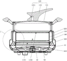
fig. 1 is a schematic structural view of a cooking appliance provided according to an embodiment of the present invention;
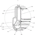
fig. 2 is a schematic cross-sectional view of a cooking appliance according to an embodiment of the present invention;
fig. 3 is another sectional view schematically illustrating a cooking appliance according to an embodiment of the present invention;
FIG. 4 is an enlarged view of a portion of FIG. 3 at I;
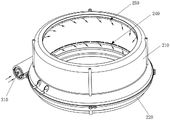
FIG. 5 is a schematic partial structural view of a base assembly of a cooking appliance provided in accordance with an embodiment of the present invention;
FIG. 6 is a schematic cross-sectional structure of the structure of FIG. 5;
FIG. 7 is a top view of the structure of FIG. 5;
FIG. 8 is a schematic structural view of the structure of FIG. 5 in an inverted state;
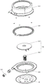
FIG. 9 is an exploded view of the structure of FIG. 5;
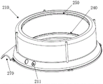
fig. 10 is a structural schematic view of an upper duct housing of a cooking appliance provided according to an embodiment of the present invention;
fig. 11 is another structural schematic view of an upper duct housing of a cooking appliance provided in accordance with an embodiment of the present invention;
fig. 12 is a sectional structure view of an upper duct housing of a cooking appliance according to an embodiment of the present invention;
fig. 13 is a schematic structural view of a heating element of a cooking appliance provided according to an embodiment of the present invention;
fig. 14 is a structural schematic view of a lower duct housing of a cooking appliance provided according to an embodiment of the present invention;
fig. 15 is another structural schematic view of a lower duct housing of a cooking appliance according to an embodiment of the present invention;
fig. 16 is a schematic structural view of a heat generating disc assembly of a cooking appliance provided in accordance with an embodiment of the present invention;
FIG. 17 is another schematic structural view of a heat generating disc assembly of a cooking appliance provided in accordance with an embodiment of the present invention;
fig. 18 is a schematic structural view of a heat retaining cover of a cooking appliance according to an embodiment of the present invention;
fig. 19 is a schematic structural view of a pot assembly of a cooking appliance provided in accordance with an embodiment of the present invention;
FIG. 20 is a schematic cross-sectional view of the structure of FIG. 19 and showing the flow path of the gas flow;
FIG. 21 is a schematic cross-sectional structure of the structure of FIG. 19;
fig. 22 is a schematic structural view of a container body of a cooking appliance provided according to an embodiment of the present invention;
FIG. 23 is a schematic cross-sectional structure view of the structure of FIG. 22;
fig. 24 is a schematic view of air flow in a duct of a cooking appliance provided in accordance with an embodiment of the present invention;
fig. 25 is a schematic view of air flow at a heating element of a cooking appliance provided in accordance with an embodiment of the present invention.
Fig. 1-25 reference numbers illustrate:
10 pan assembly, 110 container body, 1101 first container intake, 1102 second container intake, 111 cooking cavity, 113 constriction, 120 pan lid, 121 lid body, 122 handle, 1221 vent, 140 deep fat,
20 air ducts, 210 an upper air duct shell, 211 an escape port, 220 a lower air duct shell, 240 a first air outlet, 250 a second air outlet, 260 an air cavity, 270 an installation cavity,
310 air supply parts, 320 heating parts, 321 annular heating pipes, 3214 cold ends, 3215 wiring parts and 322 heat transfer sheets,
40 heat preservation cover, 50 heating plate component, 510 heating plate, 520 temperature controller,
60 base assembly, 610 base, 620 cover.
Detailed Description
The following detailed description is provided to assist the reader in obtaining a thorough understanding of the methods, devices, and/or systems described herein. However, various changes, modifications, and equivalents of the methods, apparatus, and/or systems described herein will be apparent to those skilled in the art after reviewing the disclosure of the present application. For example, the order of operations described herein is merely an example, and is not limited to those set forth herein, but may be changed as will become apparent after understanding the disclosure of the present application, except to the extent that operations must occur in a particular order. Moreover, descriptions of features known in the art may be omitted for clarity and conciseness.
The features described herein may be embodied in different forms and should not be construed as limited to the examples described herein. Rather, the examples described herein have been provided to illustrate only some of the many possible ways to implement the methods, devices, and/or systems described herein, which will be apparent after understanding the disclosure of the present application.
As used herein, the term "and/or" includes any one of the associated listed items and any combination of any two or more.
Although terms such as "first", "second", and "third" may be used herein to describe various elements, components, regions, layers or sections, these elements, components, regions, layers or sections should not be limited by these terms. Rather, these terms are only used to distinguish one element, component, region, layer or section from another element, component, region, layer or section. Thus, a first element, component, region, layer or section referred to in the examples described herein could also be referred to as a second element, component, region, layer or section without departing from the teachings of the examples.
In the specification, when an element such as a layer, region or substrate is referred to as being "on," "connected to" or "coupled to" another element, it can be directly on, connected to or coupled to the other element or one or more other elements may be present therebetween. In contrast, when an element is referred to as being "directly on," "directly connected to," or "directly coupled to" another element, there may be no intervening elements present.
The terminology used herein is for the purpose of describing various examples only and is not intended to be limiting of the disclosure. The singular is also intended to include the plural unless the context clearly indicates otherwise. The terms "comprises," "comprising," and "having" specify the presence of stated features, quantities, operations, elements, components, and/or combinations thereof, but do not preclude the presence or addition of one or more other features, quantities, operations, components, elements, and/or combinations thereof. The term "plurality" means any number of two or more.
The definitions of the directional words such as "upper", "lower", "top" and "bottom" in the present application are all defined based on the orientation of the cooking utensil when the cooking utensil is in a normal use state and is placed upright.
Unless otherwise defined, all terms including technical and scientific terms used herein have the same meaning as commonly understood by one of ordinary skill in the art to which this invention belongs after understanding the present invention. Unless explicitly defined as such herein, terms such as those defined in general dictionaries should be interpreted as having a meaning that is consistent with their meaning in the context of the relevant art and the present disclosure, and should not be interpreted in an idealized or overly formal sense.
Further, in the description of the examples, when it is considered that detailed description of well-known related structures or functions will cause a vague explanation of the present invention, such detailed description will be omitted.
A cooking appliance of some embodiments of the present application will be described below with reference to fig. 1 to 25.
As shown in fig. 2, 3, 4, 5, 6, 20, 21, 22 and 23, a first aspect of the present invention provides a cooking appliance including: a pot assembly 10, the pot assembly 10 including a container body 110 having a cooking cavity 111; the air duct 20 is arranged around the container body 110, the air duct 20 has a first air outlet 240 and a second air outlet 250 which are circumferentially distributed, the first air outlet 240 and the second air outlet 250 face the side wall direction of the container body 110, and the first air outlet 240 is located below the second air outlet 250; the side wall of the container body 110 is provided with a first container air inlet 1101 and a second container air inlet 1102 which are circumferentially distributed, the first air outlet 240 is arranged opposite to the first container air inlet 1101, and the second air outlet 250 is arranged opposite to the second container air inlet 1102; and a hot air assembly including an air supply member 310 and a heating member 320, the hot air assembly being disposed in the air duct 20, the air supply member 310 being capable of blowing air heated by the heating member 320 in the air duct 20 into the cooking chamber 111.
The cooking appliance provided by the embodiment of the present invention includes a pot assembly 10, an air duct 20 and a hot air assembly, the pot assembly 10 may be used for containing food materials and the like, the hot air assembly blows hot air out of a first air outlet 240 and a second air outlet 250 which are located at an inner ring of the air duct 20, the first air outlet 240 and the second air outlet 250 are both distributed circumferentially, and the first air outlet 240 and the second air outlet 250 respectively correspond to a first container air inlet 1101 and a second container air inlet 1102 which are arranged on a side wall of a container body 110, so that air can be fed along the circumferential direction of the container body 110, the air flow can be blown away toward the inner center of the container body 110 due to the circumferential air feeding, and the air flow is distributed uniformly in the container body 110; and first air outlet 240 is located the below of second air outlet 250, promptly, first air outlet 240 and second air outlet 250 form two air outlets that distribute one on top of the other, can make the flow of hot-air in container body 110, distribute more evenly for eat material and be heated evenly, the maturity is unanimous, it is effectual to cook, and can realize the multiaspect heating of eating the material, and then promote heating efficiency, shorten and cook for a long time.
In some embodiments, optionally, the first air outlet 240 and/or the second air outlet 250 may be circumferentially and continuously distributed openings, and at this time, the first air outlet 240 and/or the second air outlet 250 is an annular air outlet; the openings can be circumferentially distributed at intervals, and the number of the openings is multiple; likewise, the first container intake vent 1101 and/or the second container intake vent 1102 may be circumferentially continuously distributed openings, in which case the first container intake vent 1101 and/or the second container intake vent 1102 are annular intake vents; the first container intake vent 1101 and/or the second container intake vent 1102 may also be circumferentially spaced openings, and the number of openings may be multiple.
With respect to the specific structure of the cookware assembly 10, in some embodiments, as shown in fig. 2, 3, 4, and 20, the cookware assembly 10 further includes: a frying plate 140, the frying plate 140 being detachably disposed in the cooking chamber 111, the frying plate 140 being located above the first container intake vent 1101 and below the second container intake vent 1102.
In these embodiments, by providing the first container air inlet 1101 and the second container air inlet 1102 on the container body 110, the hot air can heat the food material placed on the frying plate 140 from the upper and lower surfaces simultaneously, so that the upper and lower surfaces of the food material are heated simultaneously, and thus the food material is heated more uniformly, the ripeness is consistent, and the cooking effect is good; since neither the first container air inlet 1101 nor the second container air inlet 1102 is directly opposite to the frying plate 140, hot air can be prevented from directly blowing to the food material placed on the frying plate 140 to cause scorching, and the cooking effect can be further improved.
Specifically, as an example, the frying plate 140 is provided with a plurality of oil leakage holes, which can filter grease and prevent grease from accumulating at the bottom of the food material, and the food material is too greasy.
Further, in order to enable the hot wind blown out from the second outlet 250 located above to be blown onto the food material, in some embodiments, as shown in fig. 4 and 12, the second outlet 250 is inclined downward, and the inclination angle α 8 of the second outlet 250 is 30 ° to 60 °.
In these embodiments, the provision of the second outlet 250 in an inclined configuration can serve to direct the airflow within the air cavity 260, such that the circularly rotating airflow in the air cavity 260 can be directed obliquely downward into the container body 110, such that the airflow can flow to the food material located on the fry vat 140 of the container body 110. Further, the inclination angle α 8 of the second air outlet 250 is defined within a range of 30 ° to 60 °, in which the hot air blown into the container body 110 via the first air outlet 240 can be made to reach the center of the food material distribution position, and the resistance of the hot air entering from the first container air inlet 1101 rising upward is overcome, so that the inside of the container body 110 is heated uniformly; specifically, if the inclination angle is too small, the wind may reach the surface of the food material in advance, may not reach the central range of the food material in the container body 110, may form a rotation inside the container body 110, and then may be thrown toward the sidewall of the container body 110, causing uneven heating, resulting in a central temperature lower than the outer periphery; if the inclination angle is too large, the wind can delay to reach the central range of the food material, and can exceed the central range of the food material in the container body 110, and then rotate in the container body 110, and further throw the food material to the side wall of the container body 110, so that uneven heating is caused, and the central temperature is lower than the periphery.
For the specific arrangement of the first outlet port 240 and the second outlet port 250, in some embodiments, as shown in fig. 12, the distance H3 between the first outlet port 240 and the second outlet port 250 in the vertical direction is 40mm to 80 mm. Within this range, the distance H3 between the first outlet 240 and the second outlet 250 is ensured to be appropriate, so that the problem that the food is too close to the first outlet and the second outlet is burnt and the like due to too close distance is avoided, and the problem that the cooking time is long and the food is difficult to cook due to too far heating efficiency is also avoided.
In some embodiments, as shown in fig. 12, the length W1 of the first air outlet 240 in the vertical direction is less than the length W2 of the second air outlet 250 in the vertical direction. Since the hot air rises upward, the second outlet 250 needs to be blown obliquely downward, the pressure required is greater, and thus the length W2 of the second outlet 250 in the vertical direction is set to be greater.
As shown in fig. 12, in some embodiments, the length W1 of the first air outlet 240 in the vertical direction is 1.5mm to 5 mm. In this range, the air output can be ensured, and the air speed through the first air outlet 240 is increased, so that the air flow can be distributed to most of the space in the container body 110, and the heating efficiency is ensured; specifically, if the length W1 of the first air outlet 240 in the vertical direction is too large, the flow rate of the wind is increased, the wind speed is reduced, and the hot wind cannot be blown to the surface of the food material; if the height is too small, the flow rate is reduced, the wind speed is increased, and the heating efficiency is low.
In some embodiments, the first container intake vent 1101 is 2mm to 7mm in length in the vertical direction. Within this range, the size of the first outlet port 240 can be better matched and slightly larger than the first outlet port 240, thereby reducing the leakage of the hot wind as much as possible.
As shown in fig. 12, in some embodiments, the length W2 of the second air outlet 250 in the vertical direction is 2mm to 6 mm. In this range, the air output can be ensured, and the air speed through the second air outlet 250 is increased, so that the air flow can be distributed to most of the space in the container body 110, and the heating efficiency is ensured; specifically, if the length W2 of the second air outlet 250 in the vertical direction is too large, the flow rate of the wind is increased, the wind speed is reduced, and the hot wind cannot be blown to the surface of the food material; if the height is too small, the flow rate is reduced, the wind speed is increased, and the heating efficiency is low.
In some embodiments, the second container intake vent 1102 has a length in the vertical direction of 2mm to 7 mm. Within this range, the size of the second outlet 250 can be better matched and slightly larger than the second outlet 250, thereby reducing the leakage of hot air as much as possible.
As to the specific structure of the air duct 20, in some embodiments, as shown in fig. 5 and fig. 6, an annular air cavity 260 and a mounting cavity 270 located at the periphery of the air cavity 260 are formed in the air duct 20, one end of the mounting cavity 270 communicates with the outside, the other end communicates with the air cavity 260, the air supply component 310 is disposed in the mounting cavity 270, and an air outlet surface of the air supply component 310 faces the air cavity 260.
In these embodiments, the air supply member 310 blows fresh air from the outside into the annular air chamber 260, and under the action of the air pressure, the air will rotate clockwise or counterclockwise in the air chamber 260 and be related to the position of the fan, and is blown out by the first air outlet 240 and the second air outlet 250 located at the inner ring of the air duct 20, and then enters the inside of the container body 110 through the first container inlet 1101 and the second container inlet 1102, and is blown towards the inner center of the container body 110, so that the distribution of the air flow in the container body 110 is more uniform.
In some embodiments, the air outlet direction of the air supply member 310 is tangential to the inner wall of the air cavity 260. By the arrangement, the air blown out by the air supply member 310 flows more smoothly in the annular air cavity 260, and the wind resistance is reduced.
In some embodiments, as shown in fig. 24, in the horizontal cross section, the minimum distance L7 between the air supply member 310 and the annular center line of the air cavity 260 ranges from 5mm to 25 mm. Within this range, a certain safety distance can be kept between the air supply member 310 and the heating member 320, and the air supply member 310 is prevented from being too close to the heating member 320 and being damaged due to too high temperature.
It should be noted that, because the wind cavity 260 is annular, any cross section of the wind cavity 260 is circular, and the annular center line of the wind cavity 260 is: the centers of the cross sections of the wind chambers 260 are connected to form a circle.
With respect to the specific structure of the air chute 20, in some embodiments, as shown in fig. 5, 6, 7, 8, 9, 10, 11, 12, 14, and 15, the air chute 20 includes: the upper air duct shell 210 and the lower air duct shell 220 enclose to form an air cavity 260 and an installation cavity 270; the upper duct housing 210 has two circles of vents distributed up and down toward one side of the pot assembly 10, the vents are communicated with the air chamber 260, the circle of vents located below forms a first air outlet 240, and the circle of vents located above forms a second air outlet 250.
In these embodiments, the upper duct housing 210 and the lower duct housing 220 enclose to form an air chamber 260 and a mounting chamber 270, the air chamber 260 is installed with a heating element 320, and the mounting chamber 270 is installed with an air supply element 310; further, one side of the upper air duct casing 210 facing the container body 110 is provided with two circles of air vents, the first air outlet 240 and the second air outlet 250 are respectively formed, the first air outlet 240 and the second air outlet 250 are directly formed on the upper air duct casing 210 through processing, and other structures are not required to be arranged, so that the first air outlet 240 and the second air outlet 250 are simple to process, the parts of the air duct 20 are reduced, the structure of the air duct 20 is simplified, and the air duct 20 is beneficial to production in both assembling and processing aspects.
In some embodiments, the space between two adjacent vents can reinforce the structural strength of the upper duct housing 210, and prevent the upper duct housing 210 from being broken at the first air outlet 240 and/or the second air outlet 250.
To form the second outlet 250 obliquely downward, in some embodiments, as shown in fig. 4 and 12, the top wall and the bottom wall of the second outlet 250 are gradually inclined downward toward the container body 110 to guide the annularly rotating wind obliquely downward into the pot assembly 10. By providing the top wall and the bottom wall of the second outlet 250 to be gradually inclined downward toward the container body 110, an outlet directed obliquely downward is formed, which is simple in structure and easy to implement, and the second outlet 250 directed obliquely downward can better guide the direction of the airflow so that the airflow flows toward the frying plate 140 in the container body 110.
In some embodiments, as shown in fig. 19-23, the lower portion of the container body 110 is necked inward to form a necked portion 113, and a first container inlet 1101 and a second container inlet 1102 are disposed on the necked portion 113. Because wind channel 20 encloses the periphery of establishing at vessel 110, the lower part that sets up vessel 110 forms the constriction 113 that the diameter is littleer to make wind channel 20 enclose to establish and to occupy littleer space in the periphery of constriction 113, make wind channel 20's volume littleer, be favorable to the miniaturization of product.
In some embodiments, as shown in fig. 23, the length W3 of the first container intake vent 1101 in the vertical direction is greater than the length W1 of the first outlet vent 240 in the vertical direction, where the first outlet vent 240 is located within the range of the first container intake vent 1101. By such arrangement, the first container air inlet 1101 can be aligned with the first air outlet 240, and wind flowing out of the first air outlet 240 can directly enter the first container air inlet 1101, so that leakage of hot wind is reduced as much as possible, and the heat efficiency is improved.
In some embodiments, the length W4 of the second container intake vent 1102 in the vertical direction is greater than the length W2 of the second air outlet vent 250 in the vertical direction, where the second air outlet vent 250 is located within the second container intake vent 1102. So set up for second container air intake 1102 can align with second air outlet 250, and the wind that the second air outlet 250 flows out can directly enter into second container air intake 1102 to reduce hot-blast to spill as far as possible, improve the thermal efficiency.
In some embodiments, the heating element 320 includes an annular heating tube 321. The annular heating pipe 321 can be better matched with the annular air cavity 260, and the heating area is increased as much as possible, so that the heating efficiency is high, and the heating is uniform.
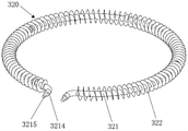
In some embodiments, as shown in fig. 13 and 25, the heating member 320 includes an annular heating pipe 321 and a plurality of heat transfer fins 322 disposed around the outer periphery of the annular heating pipe 321, and the extending direction of the heat transfer fins 322 faces the center of the air duct 20. So set up, heat transfer piece 322 can play the effect to hot-blast direction, with the center of hot-blast direction container body 110, can also effectual increase heating area improve heating efficiency.
In some embodiments, as shown in fig. 13 and 25, in the case where the heating member 320 includes the heat transfer sheet 322, the heat transfer sheet 322 is a circular sheet, and a plurality of heat transfer sheets 322 are disposed at intervals along the circumferential direction of the annular heat generating pipe 321 on the outer circumference of the annular heat generating pipe 321. The wafer has simple structure and is easy to process.
In some embodiments, as shown in fig. 13 and 25, the heat transfer fins 322 are spirally wound around the outer circumference of the annular heat-generating pipe 321 along the circumferential direction of the annular heat-generating pipe 321. The spiral heat transfer fins 322 can be tightly wound around the periphery of the annular heating tube 321, and are more favorable for assembly with the annular heating tube 321.
In some embodiments, as shown in fig. 9, 10, 13 and 25, the annular heating tube 321 includes a cold end 3214 and a wiring portion 3215, an avoiding opening 211 is provided on the upper duct housing 210, and the wiring portion 3215 extends from the avoiding opening 211 to the outside of the upper duct housing 210 for connecting a power supply.
In some embodiments, as shown in fig. 25, an angle α 9 between an extending direction of one of the heat transfer sheets 322, which can be tangent to an extension line of the axis of the air supply member 310, and the axis of the air supply member 310 is an obtuse angle. With such an arrangement, the guiding resistance of the airflow blown by the air supply member 310 can be reduced, and the airflow can flow more smoothly.
In some embodiments, the diameter of the ring-shaped heat-generating pipe 321 is 5mm to 8 mm. If the pipe diameter is too large, the air duct 20 needs to be enlarged at the same time, so that the whole machine is overstaffed and the cost is increased; however, if the pipe diameter is too small, the heat dissipation area is small, the heat is concentrated, and the annular heating pipe 321 is easily damaged.
In some embodiments, the heat transfer fins 322 have a diameter of 10mm to 25 mm. If the diameter of the heat transfer sheet 322 is too large, the air duct 20 needs to be enlarged at the same time, so that the whole machine is too bulky and the cost is increased; however, if the diameter of the heat transfer fin 322 is too small, the heat dissipation area is small, the heat is concentrated, and the annular heat pipe 321 is easily damaged.
In some embodiments, as shown in fig. 3, 6, 7, 8, 9, 16, 17 and 18, the cooking appliance further comprises: the heat preservation cover 40 is arranged below the air duct 20, and the heat preservation cover 40 is used for heat insulation; the heating disc assembly 50 is arranged on the heat preservation cover 40, the air duct 20 is annular, and the heating disc assembly 50 is located in the middle of the air duct 20 and can heat the container body 110.
In the embodiments, the heat-insulating cover 40 can insulate heat, prevent heat from overflowing and improve heating efficiency; further, the heating disc assembly 50 is disposed in the middle of the air duct 20, so that the heating disc assembly 50 can be used for heating the container body 110 mounted above the heating disc assembly, and double heating of the food material in the container body 110 is achieved. Or, after the container body 110 is taken down, the heating disc assembly can be used for heating a small pot placed on the heating disc assembly, and is used for cooking, steaming, frying food materials and the like, so that the multifunctional container is multifunctional.
It should be noted that the heating plate assembly 50 and the heating member 320 may work simultaneously or separately, and the user may select the heating plate assembly according to specific requirements, so as to expand the application range of the product.
In some embodiments, optionally, the heat-insulating cover 40 is provided with a flange and a fixing portion, the flange is used for expanding the volume of a cavity formed by the lower air duct shell 220 and the heat-insulating cover 40, so as to provide a sufficient accommodating space for the heat-generating plate assembly 50, and the fixing portion is used for being fixedly connected with the lower air duct shell 220, and specifically, can be fastened on the lower air duct shell 220 by passing through the fixing portion through a fastening member such as a screw.
In some embodiments, as shown in fig. 1, 2, 3, 19, 20 and 21, the cookware assembly 10 further comprises: the pot cover 120 can be covered on the container body 110, the pot cover 120 comprises a handle 122 arranged on the cover body 121 by the cover body 121, and the handle 122 is provided with an exhaust hole 1221 communicated with the inside of the container body 110. The hot air after cooking can be exhausted through the air outlet 1221 of the handle 122, so as to form the external circulation air duct 20, so that fresh air is blown into the container body 110 every time, and the food materials are not tainted.
In some embodiments, as shown in fig. 1 to 3 and 19, 20 and 21, the vent hole 1221 is formed in the side wall of the handle 122 to allow hot air to be discharged toward the side, so that the user is prevented from being easily scalded by exhausting air straight upward, and the user can select the orientation of the vent hole 1221 to facilitate the cooking operation.
In some embodiments, as shown in fig. 1, 2 and 3, the cooking appliance further includes a base assembly 60, the base assembly 60 includes a base 610 and an upper cover 620, the upper cover 620 covers the base 610 and encloses with the base 610 to form a containing cavity, the air duct 20 is disposed in the containing cavity, a through hole for containing the pot assembly 10 is formed in the middle of the upper cover 620, and the pot assembly 10 is detachably mounted on the base assembly 60 through the through hole.
In these embodiments, the air duct 20 is disposed in the base assembly 60, the pot assembly 10 is placed on the base assembly 60, and a structure that can be separated from the top to the bottom is formed, when cooking, the heating element 320 and/or the heating plate assembly 50 in the base assembly 60 can heat the pot assembly 10, and hot air can rise, so that the heating effect is more uniform.
Specifically describing the flow path of the cooking apparatus in the embodiment of the present application, the air supply member 310 blows fresh air from the outside into the air duct 20 with the heating member 320, and the air rotates clockwise (from top to bottom) along with the annular air duct 20; heated air is blown into the container body 110 through the first air outlet 240 and the second air outlet 250, and hot air blown from the first air outlet 240 is located below the frying plate 140; the hot air blown from the second air outlet 250 is positioned above the frying plate 140; the hot air rotates in the container body 110, and the upper and lower surfaces of the hot air simultaneously heat the food material on the frying plate 140; since the upper and lower surfaces of the food material are heated at the same time, uniform heating is realized.
Alternatively, the air supply 310 may be a fan, preferably an axial fan.
It is understood that the exterior of the container body 110 may have an outer shell for preventing heat from being diffused, preventing burn, etc.; the container body 110 internally forms a cooking cavity 111. In addition, the shell can be provided with a handle, so that the shell is convenient to take and place.
Further, optionally, the upper cover 620 is connected to the base 610 by fasteners such as screws.
In some embodiments, optionally, the cooking appliance is an air fryer.
Although the embodiments of the present invention have been described in detail above, those skilled in the art may make various modifications and variations to the embodiments of the present invention without departing from the spirit and scope of the invention. It should be understood that such modifications and variations that may appear to those skilled in the art will still fall within the spirit and scope of the embodiments of the invention as defined by the appended claims.
Claims (15)
1. A cooking appliance, comprising:
a pot assembly (10), the pot assembly (10) comprising a container body (110) having a cooking cavity (111);
the air duct (20) is arranged around the container body (110) in an enclosing manner, the air duct (20) is provided with a first air outlet (240) and a second air outlet (250), the first air outlet (240) and the second air outlet (250) are distributed in the circumferential direction, the first air outlet (240) and the second air outlet (250) face the direction of the side wall of the container body (110), and the first air outlet (240) is located below the second air outlet (250);
the side wall of the container body (110) is provided with a first container air inlet (1101) and a second container air inlet (1102), wherein the first container air inlet (1101) and the second container air inlet (1102) are circumferentially distributed, the first air outlet (240) is arranged opposite to the first container air inlet (1101), and the second air outlet (250) is arranged opposite to the second container air inlet (1102);
a hot air assembly including an air supply member (310) and a heating member (320), the hot air assembly being provided in the air duct (20), the air supply member (310) being capable of blowing air heated by the heating member (320) in the air duct (20) into the cooking chamber (111).
2. The cooking appliance according to claim 1, characterized in that the pot assembly (10) further comprises:
a frying plate (140), the frying plate (140) being detachably disposed in the cooking chamber (111), the frying plate (140) being located above the first container intake vent (1101) and below the second container intake vent (1102).
3. The cooking appliance of claim 1,
the second air outlet (250) inclines downwards, and the inclination angle of the second air outlet (250) is 30-60 degrees.
4. The cooking appliance of claim 1,
the distance between the first air outlet (240) and the second air outlet (250) along the vertical direction is 40mm to 80 mm.
5. The cooking appliance of claim 1,
the length of the first air outlet (240) in the vertical direction is smaller than that of the second air outlet (250); and/or
The length of the first air outlet (240) in the vertical direction is 1.5mm to 5 mm; and/or
The length of the second air outlet (250) in the vertical direction is 2mm to 6 mm.
6. The cooking appliance according to any one of claims 1 to 5,
an annular air cavity (260) and a mounting cavity (270) located on the periphery of the air cavity (260) are formed in the air duct (20), one end of the mounting cavity (270) is communicated to the outside, the other end of the mounting cavity is communicated with the air cavity (260), the air supply piece (310) is arranged in the mounting cavity (270), and the air outlet surface of the air supply piece (310) faces the air cavity (260).
7. The cooking appliance according to claim 6, wherein the air duct (20) comprises:
the air duct structure comprises an upper air duct shell (210) and a lower air duct shell (220), wherein the upper air duct shell (210) and the lower air duct shell (220) enclose to form an air cavity (260) and an installation cavity (270);
go up wind channel casing (210) orientation two rings of blow vents that distribute about having one side of pan subassembly (10), the blow vent with wind chamber (260) are linked together, and the round blow vent that is located the below forms first air outlet (240), the round blow vent that is located the top forms second air outlet (250).
8. The cooking appliance of claim 7,
the top wall and the bottom wall of the second air outlet (250) are gradually inclined downwards towards the direction of the container body (110) so as to guide the annularly rotating air into the cooker component (10) in a downward inclined mode.
9. The cooking appliance according to any one of claims 1 to 5,
the length of the first container air inlet (1101) in the vertical direction is greater than the length of the first air outlet (240) in the vertical direction, and the first air outlet (240) is located within the range of the first container air inlet (1101) in the vertical direction;
the length of the second container air inlet (1102) in the vertical direction is greater than the length of the second air outlet (250) in the vertical direction, and the second air outlet (250) is located within the range of the second container air inlet (1102) in the vertical direction.
10. The cooking appliance according to any one of claims 1 to 5,
the heating member (320) includes an annular heat generating pipe (321); or
The heating element (320) comprises an annular heating pipe (321) and a plurality of heat transfer sheets arranged around the periphery of the annular heating pipe (321), and the extending direction of the heat transfer sheets faces to the center of the air duct (20).
11. The cooking appliance of claim 10,
under the condition that the heating element (320) comprises heat transfer sheets, the heat transfer sheets are round sheets, and a plurality of heat transfer sheets are arranged on the periphery of the annular heating pipe (321) at intervals along the circumferential direction of the annular heating pipe (321); or
The heat transfer sheet is spirally coiled on the periphery of the annular heating tube (321) along the circumferential direction of the annular heating tube (321).
12. The cooking appliance of claim 11,
the included angle between the extending direction of one of the heat transfer sheets which can be tangent to the extension line of the axis of the air supply piece (310) and the axis of the air supply piece (310) is an obtuse angle; and/or
The pipe diameter of the heating pipe is 5mm to 8 mm; and/or
The heat transfer sheet has a diameter of 10mm to 25 mm.
13. The cooking appliance according to any one of claims 1 to 5, further comprising:
the heat preservation cover (40) is arranged below the air duct (20), and the heat preservation cover (40) is used for heat insulation;
the heating disc assembly (50) is arranged on the heat preservation cover (40), the air duct (20) is annular, and the heating disc assembly (50) is located in the middle of the air duct (20) and can heat the container body (110).
14. The cooking appliance according to any one of claims 1 to 5, wherein the pot assembly (10) further comprises:
the pot cover (120) can be covered on the container body (110), the pot cover (120) comprises a cover body (121), a lifting handle (122) is arranged on the cover body (121), and an exhaust hole (1221) communicated with the inside of the container body (110) is formed in the lifting handle (122).
15. The cooking appliance according to any one of claims 1 to 5, further comprising a base assembly (60), wherein the base assembly (60) comprises a base (610) and an upper cover (620), the upper cover (620) covers the base (610) and encloses with the base (610) to form a containing cavity, the air duct (20) is arranged in the containing cavity, the middle part of the upper cover (620) is provided with a through hole for containing the pot assembly (10), and the pot assembly (10) is detachably mounted on the base assembly (60) through the through hole.
Priority Applications (1)
| Application Number | Priority Date | Filing Date | Title |
|---|---|---|---|
| CN202210937777.5A CN115054134A (en) | 2022-08-05 | 2022-08-05 | Cooking utensil |
Applications Claiming Priority (1)
| Application Number | Priority Date | Filing Date | Title |
|---|---|---|---|
| CN202210937777.5A CN115054134A (en) | 2022-08-05 | 2022-08-05 | Cooking utensil |
Publications (1)
| Publication Number | Publication Date |
|---|---|
| CN115054134A true CN115054134A (en) | 2022-09-16 |
Family
ID=83207835
Family Applications (1)
| Application Number | Title | Priority Date | Filing Date |
|---|---|---|---|
| CN202210937777.5A Pending CN115054134A (en) | 2022-08-05 | 2022-08-05 | Cooking utensil |
Country Status (1)
| Country | Link |
|---|---|
| CN (1) | CN115054134A (en) |
Cited By (1)
| Publication number | Priority date | Publication date | Assignee | Title |
|---|---|---|---|---|
| CN116236076A (en) * | 2023-03-31 | 2023-06-09 | 广东伊莱特电器有限公司 | Auxiliary heating device and cooking utensil |
Citations (9)
| Publication number | Priority date | Publication date | Assignee | Title |
|---|---|---|---|---|
| CN103142151A (en) * | 2012-09-24 | 2013-06-12 | 张一骋 | Smokeless air fryer |
| CN203634023U (en) * | 2013-10-29 | 2014-06-11 | 上官林 | Air frying pan |
| CN209564021U (en) * | 2018-09-27 | 2019-11-01 | 浙江天喜厨电股份有限公司 | A kind of air ovens |
| CN110754965A (en) * | 2019-11-29 | 2020-02-07 | 广东新宝电器股份有限公司 | Air frying oven |
| CN213248570U (en) * | 2020-08-13 | 2021-05-25 | 浙江绍兴苏泊尔生活电器有限公司 | Frying basket and cooking utensil with same |
| CN113331701A (en) * | 2021-05-25 | 2021-09-03 | 广东伊莱特电器有限公司 | Machine is fried to hidden air |
| CN214712115U (en) * | 2020-09-04 | 2021-11-16 | 广州市拓璞电器发展有限公司 | Baking device |
| WO2022129100A1 (en) * | 2020-12-18 | 2022-06-23 | Koninklijke Philips N.V. | Air fryer |
| CN217907422U (en) * | 2022-08-05 | 2022-11-29 | 浙江绍兴苏泊尔生活电器有限公司 | Cooking utensil |
-
2022
- 2022-08-05 CN CN202210937777.5A patent/CN115054134A/en active Pending
Patent Citations (9)
| Publication number | Priority date | Publication date | Assignee | Title |
|---|---|---|---|---|
| CN103142151A (en) * | 2012-09-24 | 2013-06-12 | 张一骋 | Smokeless air fryer |
| CN203634023U (en) * | 2013-10-29 | 2014-06-11 | 上官林 | Air frying pan |
| CN209564021U (en) * | 2018-09-27 | 2019-11-01 | 浙江天喜厨电股份有限公司 | A kind of air ovens |
| CN110754965A (en) * | 2019-11-29 | 2020-02-07 | 广东新宝电器股份有限公司 | Air frying oven |
| CN213248570U (en) * | 2020-08-13 | 2021-05-25 | 浙江绍兴苏泊尔生活电器有限公司 | Frying basket and cooking utensil with same |
| CN214712115U (en) * | 2020-09-04 | 2021-11-16 | 广州市拓璞电器发展有限公司 | Baking device |
| WO2022129100A1 (en) * | 2020-12-18 | 2022-06-23 | Koninklijke Philips N.V. | Air fryer |
| CN113331701A (en) * | 2021-05-25 | 2021-09-03 | 广东伊莱特电器有限公司 | Machine is fried to hidden air |
| CN217907422U (en) * | 2022-08-05 | 2022-11-29 | 浙江绍兴苏泊尔生活电器有限公司 | Cooking utensil |
Cited By (1)
| Publication number | Priority date | Publication date | Assignee | Title |
|---|---|---|---|---|
| CN116236076A (en) * | 2023-03-31 | 2023-06-09 | 广东伊莱特电器有限公司 | Auxiliary heating device and cooking utensil |
Similar Documents
| Publication | Publication Date | Title |
|---|---|---|
| US7059240B2 (en) | Double heating-type pots | |
| CN110840285A (en) | Air fryer facilitating cooling of shell | |
| CN115054133A (en) | Cooking utensil | |
| CN110150957B (en) | Cooking utensil with stable airflow | |
| CN210961428U (en) | Cooking utensil convenient for heat dissipation | |
| CN217907422U (en) | Cooking utensil | |
| CN110840240A (en) | Multifunctional cooking utensil | |
| CN211155189U (en) | Cooking utensil | |
| US20240315484A1 (en) | Cooking appliance | |
| CN115054134A (en) | Cooking utensil | |
| CN217907421U (en) | Cooking utensil | |
| CN116725387A (en) | Air fryer with three-dimensional hot air circulation | |
| KR101196924B1 (en) | Multi-function cooking device | |
| CN217885790U (en) | Air duct assembly and cooking appliance | |
| WO2024212514A1 (en) | Air frying basket and air fryer | |
| CN217907423U (en) | Air duct assembly and cooking appliance | |
| CN211582736U (en) | Air fryer facilitating cooling of shell | |
| CN218942814U (en) | Cooking utensil | |
| CN115500709B (en) | Air frying pan | |
| WO2023279822A1 (en) | Heating assembly and cooking appliance having same | |
| CN217885789U (en) | Cooking utensil | |
| CN211933727U (en) | Avoid horizontal exhaust food electric baking utensil of steam | |
| CN115137236A (en) | Cooking utensil | |
| CN115054132A (en) | Air duct assembly and cooking appliance | |
| CN218635844U (en) | Air frying pan |
Legal Events
| Date | Code | Title | Description |
|---|---|---|---|
| PB01 | Publication | ||
| PB01 | Publication | ||
| SE01 | Entry into force of request for substantive examination | ||
| SE01 | Entry into force of request for substantive examination |