CN1150503C - Image display device and method - Google Patents
Image display device and method Download PDFInfo
- Publication number
- CN1150503C CN1150503C CNB981033768A CN98103376A CN1150503C CN 1150503 C CN1150503 C CN 1150503C CN B981033768 A CNB981033768 A CN B981033768A CN 98103376 A CN98103376 A CN 98103376A CN 1150503 C CN1150503 C CN 1150503C
- Authority
- CN
- China
- Prior art keywords
- light
- light source
- spatial light
- pixel
- light modulator
- Prior art date
- Legal status (The legal status is an assumption and is not a legal conclusion. Google has not performed a legal analysis and makes no representation as to the accuracy of the status listed.)
- Expired - Lifetime
Links
Images


Classifications
-
- G—PHYSICS
- G09—EDUCATION; CRYPTOGRAPHY; DISPLAY; ADVERTISING; SEALS
- G09G—ARRANGEMENTS OR CIRCUITS FOR CONTROL OF INDICATING DEVICES USING STATIC MEANS TO PRESENT VARIABLE INFORMATION
- G09G3/00—Control arrangements or circuits, of interest only in connection with visual indicators other than cathode-ray tubes
- G09G3/20—Control arrangements or circuits, of interest only in connection with visual indicators other than cathode-ray tubes for presentation of an assembly of a number of characters, e.g. a page, by composing the assembly by combination of individual elements arranged in a matrix no fixed position being assigned to or needed to be assigned to the individual characters or partial characters
- G09G3/34—Control arrangements or circuits, of interest only in connection with visual indicators other than cathode-ray tubes for presentation of an assembly of a number of characters, e.g. a page, by composing the assembly by combination of individual elements arranged in a matrix no fixed position being assigned to or needed to be assigned to the individual characters or partial characters by control of light from an independent source
- G09G3/36—Control arrangements or circuits, of interest only in connection with visual indicators other than cathode-ray tubes for presentation of an assembly of a number of characters, e.g. a page, by composing the assembly by combination of individual elements arranged in a matrix no fixed position being assigned to or needed to be assigned to the individual characters or partial characters by control of light from an independent source using liquid crystals
- G09G3/3611—Control of matrices with row and column drivers
- G09G3/3622—Control of matrices with row and column drivers using a passive matrix
- G09G3/3629—Control of matrices with row and column drivers using a passive matrix using liquid crystals having memory effects, e.g. ferroelectric liquid crystals
-
- G—PHYSICS
- G09—EDUCATION; CRYPTOGRAPHY; DISPLAY; ADVERTISING; SEALS
- G09G—ARRANGEMENTS OR CIRCUITS FOR CONTROL OF INDICATING DEVICES USING STATIC MEANS TO PRESENT VARIABLE INFORMATION
- G09G3/00—Control arrangements or circuits, of interest only in connection with visual indicators other than cathode-ray tubes
- G09G3/20—Control arrangements or circuits, of interest only in connection with visual indicators other than cathode-ray tubes for presentation of an assembly of a number of characters, e.g. a page, by composing the assembly by combination of individual elements arranged in a matrix no fixed position being assigned to or needed to be assigned to the individual characters or partial characters
- G09G3/34—Control arrangements or circuits, of interest only in connection with visual indicators other than cathode-ray tubes for presentation of an assembly of a number of characters, e.g. a page, by composing the assembly by combination of individual elements arranged in a matrix no fixed position being assigned to or needed to be assigned to the individual characters or partial characters by control of light from an independent source
- G09G3/3406—Control of illumination source
-
- G—PHYSICS
- G09—EDUCATION; CRYPTOGRAPHY; DISPLAY; ADVERTISING; SEALS
- G09G—ARRANGEMENTS OR CIRCUITS FOR CONTROL OF INDICATING DEVICES USING STATIC MEANS TO PRESENT VARIABLE INFORMATION
- G09G2310/00—Command of the display device
- G09G2310/02—Addressing, scanning or driving the display screen or processing steps related thereto
- G09G2310/0235—Field-sequential colour display
-
- G—PHYSICS
- G09—EDUCATION; CRYPTOGRAPHY; DISPLAY; ADVERTISING; SEALS
- G09G—ARRANGEMENTS OR CIRCUITS FOR CONTROL OF INDICATING DEVICES USING STATIC MEANS TO PRESENT VARIABLE INFORMATION
- G09G2310/00—Command of the display device
- G09G2310/02—Addressing, scanning or driving the display screen or processing steps related thereto
- G09G2310/024—Scrolling of light from the illumination source over the display in combination with the scanning of the display screen
-
- G—PHYSICS
- G09—EDUCATION; CRYPTOGRAPHY; DISPLAY; ADVERTISING; SEALS
- G09G—ARRANGEMENTS OR CIRCUITS FOR CONTROL OF INDICATING DEVICES USING STATIC MEANS TO PRESENT VARIABLE INFORMATION
- G09G2310/00—Command of the display device
- G09G2310/08—Details of timing specific for flat panels, other than clock recovery
-
- G—PHYSICS
- G09—EDUCATION; CRYPTOGRAPHY; DISPLAY; ADVERTISING; SEALS
- G09G—ARRANGEMENTS OR CIRCUITS FOR CONTROL OF INDICATING DEVICES USING STATIC MEANS TO PRESENT VARIABLE INFORMATION
- G09G2320/00—Control of display operating conditions
- G09G2320/02—Improving the quality of display appearance
- G09G2320/0233—Improving the luminance or brightness uniformity across the screen
-
- G—PHYSICS
- G09—EDUCATION; CRYPTOGRAPHY; DISPLAY; ADVERTISING; SEALS
- G09G—ARRANGEMENTS OR CIRCUITS FOR CONTROL OF INDICATING DEVICES USING STATIC MEANS TO PRESENT VARIABLE INFORMATION
- G09G2320/00—Control of display operating conditions
- G09G2320/02—Improving the quality of display appearance
- G09G2320/0247—Flicker reduction other than flicker reduction circuits used for single beam cathode-ray tubes
-
- G—PHYSICS
- G09—EDUCATION; CRYPTOGRAPHY; DISPLAY; ADVERTISING; SEALS
- G09G—ARRANGEMENTS OR CIRCUITS FOR CONTROL OF INDICATING DEVICES USING STATIC MEANS TO PRESENT VARIABLE INFORMATION
- G09G2320/00—Control of display operating conditions
- G09G2320/06—Adjustment of display parameters
- G09G2320/0626—Adjustment of display parameters for control of overall brightness
- G09G2320/064—Adjustment of display parameters for control of overall brightness by time modulation of the brightness of the illumination source
-
- G—PHYSICS
- G09—EDUCATION; CRYPTOGRAPHY; DISPLAY; ADVERTISING; SEALS
- G09G—ARRANGEMENTS OR CIRCUITS FOR CONTROL OF INDICATING DEVICES USING STATIC MEANS TO PRESENT VARIABLE INFORMATION
- G09G3/00—Control arrangements or circuits, of interest only in connection with visual indicators other than cathode-ray tubes
- G09G3/20—Control arrangements or circuits, of interest only in connection with visual indicators other than cathode-ray tubes for presentation of an assembly of a number of characters, e.g. a page, by composing the assembly by combination of individual elements arranged in a matrix no fixed position being assigned to or needed to be assigned to the individual characters or partial characters
- G09G3/2007—Display of intermediate tones
- G09G3/2018—Display of intermediate tones by time modulation using two or more time intervals
- G09G3/2022—Display of intermediate tones by time modulation using two or more time intervals using sub-frames
-
- G—PHYSICS
- G09—EDUCATION; CRYPTOGRAPHY; DISPLAY; ADVERTISING; SEALS
- G09G—ARRANGEMENTS OR CIRCUITS FOR CONTROL OF INDICATING DEVICES USING STATIC MEANS TO PRESENT VARIABLE INFORMATION
- G09G3/00—Control arrangements or circuits, of interest only in connection with visual indicators other than cathode-ray tubes
- G09G3/20—Control arrangements or circuits, of interest only in connection with visual indicators other than cathode-ray tubes for presentation of an assembly of a number of characters, e.g. a page, by composing the assembly by combination of individual elements arranged in a matrix no fixed position being assigned to or needed to be assigned to the individual characters or partial characters
- G09G3/34—Control arrangements or circuits, of interest only in connection with visual indicators other than cathode-ray tubes for presentation of an assembly of a number of characters, e.g. a page, by composing the assembly by combination of individual elements arranged in a matrix no fixed position being assigned to or needed to be assigned to the individual characters or partial characters by control of light from an independent source
Landscapes
- Engineering & Computer Science (AREA)
- Physics & Mathematics (AREA)
- Computer Hardware Design (AREA)
- General Physics & Mathematics (AREA)
- Theoretical Computer Science (AREA)
- Chemical & Material Sciences (AREA)
- Crystallography & Structural Chemistry (AREA)
- Control Of Indicators Other Than Cathode Ray Tubes (AREA)
- Liquid Crystal Display Device Control (AREA)
- Liquid Crystal (AREA)
Abstract
提供一种图像显示装置和方法,其即使利用进行双态的光调制的空间光调制也能按照渐变的光强得到满意的显示。利用空间光调制器3对来自光源1的光进行调制,该调制器以对应于需显示的图像的像素数据的方式对其中的每一像素处的光进行调制。当空间光调制器3中的像素状态变化时,关断光源1。当空间光调制器3中的像素状态稳定时,来自光源1的光脉冲照射到空间光调制器3上以显示图像。
To provide an image display device and method capable of obtaining satisfactory display according to gradational light intensity even with spatial light modulation that performs binary light modulation. The light from the light source 1 is modulated by a spatial light modulator 3, which modulates the light at each pixel thereof in a manner corresponding to the pixel data of the image to be displayed. When the state of a pixel in the spatial light modulator 3 changes, the light source 1 is turned off. When the state of the pixels in the spatial light modulator 3 is stable, light pulses from the light source 1 are irradiated onto the spatial light modulator 3 to display images.
Description
技术领域technical field
本发明涉及一种用于显示图像的装置和方法,其利用一空间光调制器通过对来自光源的入射光进行调制业显示图像,这种调制器对在图像的每一像素处的光按双状态(binary)方式进行调制。The present invention relates to a device and method for displaying an image by modulating incident light from a light source by means of a spatial light modulator which modulates the light at each pixel of the image in a double The state (binary) mode is modulated.
背景技术Background technique
各种利用液晶板作为一空间光调制器的液晶显示装置作为图像显示装置已广为使用,这些装置利用对在其每一像素的光进行调制的空间光调制器,通过对来自光源的入射光进行调制来显示图像。很多这类常规的图像显示装置属于使用TN液晶或STN液晶作为液晶板的类型,液晶状态连续变化,对光强进行调制。然而,这些液晶板响应速度慢,不能高速工作。Various liquid crystal display devices using a liquid crystal panel as a spatial light modulator have been widely used as image display devices. These devices use a spatial light modulator for modulating light at each pixel thereof, by adjusting the incident light from a light source. Modulate to display the image. Many such conventional image display devices are of the type using TN liquid crystal or STN liquid crystal as a liquid crystal panel, and the state of the liquid crystal is continuously changed to modulate the light intensity. However, these liquid crystal panels are slow in response and cannot operate at high speed.
为了解决常规液晶板的这些问题,提出一种空间光调制器,其由一种能够快速工作的光调制材料例如铁电液晶(FLC)制成。然而,该光调制材料例如FLC难于连续改变状态,并且通常仅取两种状态。因此,利用这种光调制材料的空间光调制器进行的光调制仅使光通过和关断,即进行双态光调制。In order to solve these problems of the conventional liquid crystal panel, a spatial light modulator is proposed, which is made of a light modulating material capable of fast operation such as ferroelectric liquid crystal (FLC). However, it is difficult for such light modulating materials such as FLC to change states continuously, and usually only adopts two states. Therefore, the light modulation performed by the spatial light modulator using this light modulation material only makes light pass and turn off, that is, performs binary light modulation.
为了在利用这种空间光调制器的图像显示装置中按逐渐变化的光强显示,利用控制入射光通断的空间光调制器进行脉宽调制。人眼具有视觉暂留效应,使得作用在眼睛上的入射光量被积分,这种积分的结果是按光强被识别的。这样,如果能够按照足够高速度进行脉宽调制,人眼会这样识别入射光,即好像该光的光强是渐变的。In order to display with gradually changing light intensity in an image display device using such a spatial light modulator, pulse width modulation is performed by using a spatial light modulator that controls on-off of incident light. The human eye has a persistence of vision effect, so that the amount of incident light acting on the eye is integrated, and the result of this integration is recognized according to the light intensity. Thus, if pulse width modulation can be performed at a sufficiently high speed, the human eye will perceive incoming light as if it had a gradual change in intensity.
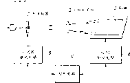
图1表示这些图像显示装置的基本概念。光源101通过光照射用光学系统102将光照射到空间光调制器103上。由空间光调制器103反射的光由一光投影用光学系统104投影到屏幕105上。因此,在屏幕105上显示图像。光源101是连续通电的以便形成具有预定光强的光,并由该使光源101的光通断的空间光调制器103对来自光源101的光进行脉宽调制。应当认识到,虽然在图1中的空间光调制器103是反射型的,但其也可以是透射型的。FIG. 1 shows the basic concept of these image display devices. The light source 101 irradiates light onto the spatial light modulator 103 through the optical system 102 for light irradiation. The light reflected by the spatial light modulator 103 is projected onto a screen 105 by a light projection optical system 104 . Accordingly, an image is displayed on the screen 105 . The light source 101 is continuously energized to form light with a predetermined light intensity, and the light from the light source 101 is pulse-width modulated by the spatial light modulator 103 that switches the light of the light source 101 on and off. It should be appreciated that although the spatial light modulator 103 in FIG. 1 is reflective, it could also be transmissive.
图2表示在上述图像显示装置中采用的用于实现按渐变光强显示的脉宽调制的基本原理。图2表示由空间光调制器103实行的调制方式与由人眼可识别的光强(可识别的亮度)之间的相互关系。如图所示,人眼会对由空间调制器103反射和调制的光量进行积分,并识别该积分值当作光强。因此,即使实际的光强是恒定的,由于由空间光调制器103所反射的光脉冲的宽度是变化的,由人眼识别的光强将对应于脉冲宽度变化的幅度而变化。因此,通过控制空间光调制器103的调制方式,就能够进行光调制。FIG. 2 shows the basic principle of pulse width modulation employed in the above-mentioned image display device for realizing display with gradational light intensity. FIG. 2 shows the correlation between the modulation method performed by the spatial light modulator 103 and the light intensity (recognizable brightness) recognizable by human eyes. As shown in the figure, the human eye integrates the amount of light reflected and modulated by the spatial modulator 103, and recognizes the integrated value as light intensity. Therefore, even though the actual light intensity is constant, since the width of the light pulse reflected by the spatial light modulator 103 varies, the light intensity recognized by human eyes will vary corresponding to the magnitude of the pulse width variation. Therefore, light modulation can be performed by controlling the modulation method of the spatial light modulator 103 .
然而,如在图3A中所示,如果在空间光调制器103的平面内的一个区域中的特性(性能)A与在另一具区域中的特性(性能)B不同,即如果在空间光调制器103的通/断特性方面存在平面内的变化,则由空间光调制器103所调制的光的光强响应由一个区域到另一个区域是变化的,导致由人眼识别的光强是变化的。更具体地说,如果空间光调制器103由一个区域到另一个区域的平面内特征是变化的,由于以通过脉冲宽度调制实现光强调节为依据,光脉冲的强度和形状也将由一个平面内的区域到另一个区域是变化的,使得光强将是不均匀的。However, as shown in FIG. 3A, if the characteristic (performance) A in one region within the plane of the spatial light modulator 103 is different from the characteristic (performance) B in another region, that is, if the spatial light There is an in-plane variation in the on/off characteristics of the modulator 103, and the light intensity response of the light modulated by the spatial light modulator 103 varies from one area to another, resulting in the light intensity recognized by the human eye being change. More specifically, if the in-plane characteristics of the spatial light modulator 103 vary from one region to another, the intensity and shape of the light pulse will also vary from one in-plane The area is varied from area to area so that the light intensity will be non-uniform.
若使在空间光调制器103的平面内的特性完全均匀就能解决这一问题。然而,要使在空间光调制器103的平面范围内的特性完全均匀是极为困难的。因此,利用常规的图像显示装置难于消除由于空间光调制器103的特性的不均匀的平面内分布所造成的光强不均匀。This problem can be solved by making the characteristics in the plane of the spatial light modulator 103 completely uniform. However, it is extremely difficult to make the characteristics of the spatial light modulator 103 completely uniform within the plane range. Therefore, it is difficult to eliminate the non-uniformity of light intensity due to the non-uniform in-plane distribution of the characteristics of the spatial light modulator 103 with a conventional image display device.
对于数目增加的亮度持续有限的时间的脉宽调制,必须要降低最小脉冲宽度。例如,在一种通常的图像显示装置中,一屏图像的显示时间约为16毫秒,应在这一段时间内进行脉冲宽度调制,以按渐变的光强进行显示。假设在16毫秒的时间内实现脉宽调节,如果光强数据为8比特(bit)并且具有256亮度级,则所需最小脉冲宽度须为62微秒。徜若光强数据为10比特,并具有1024亮度级,则最小脉冲宽度须为15微秒。For pulse width modulation with an increased number of luminances for a limited time, the minimum pulse width must be reduced. For example, in a common image display device, the display time of one screen image is about 16 milliseconds, and pulse width modulation should be performed during this period of time to display with gradually changing light intensity. Assuming that the pulse width adjustment is realized within 16 milliseconds, if the light intensity data is 8 bits and has 256 brightness levels, the required minimum pulse width must be 62 microseconds. If the light intensity data is 10 bits and has 1024 brightness levels, the minimum pulse width must be 15 microseconds.
更具体地说,为了利用脉宽调制按照渐变的光强显示图像,最小脉冲宽度应为几十微秒。由于TN液晶和STN液晶的响应速度为几毫秒到几百毫秒,最小脉冲宽度不可能为几十微秒。对比起来,光调制材料(例如FLC)可达到的最小脉冲宽度为几十微秒。然而,即使使用具有高响应速度的光调制材料,例如FLC,也需要利用很高的电压来激励光调制材料,以便达到这样小的最小脉冲宽度。即对于激励光调制材料的要求是很难满足的。因此,在利用一能对光进行双态调制的空间光调制器的常规图像显示装置中的脉宽调制不能按照渐变的光强满意地显示图像。More specifically, in order to display images according to gradational light intensity using pulse width modulation, the minimum pulse width should be several tens of microseconds. Since the response speed of TN liquid crystal and STN liquid crystal is several milliseconds to hundreds of milliseconds, the minimum pulse width cannot be tens of microseconds. In contrast, the minimum pulse width achievable by light modulating materials such as FLC is tens of microseconds. However, even with a light modulation material having a high response speed, such as FLC, it is necessary to excite the light modulation material with a very high voltage in order to achieve such a small minimum pulse width. That is, the requirements for exciting light-modulating materials are difficult to meet. Therefore, pulse width modulation in a conventional image display device using a spatial light modulator capable of binary modulation of light cannot satisfactorily display an image in accordance with gradually changing light intensities.
发明内容Contents of the invention
因此,本发明的目的是通过提供一种图像显示装置和方法来克服上述在先技术存在的缺点,这种装置和方法,即使利用能提供双态的光或光调制的空间光调制器,也能按照渐变的光强满意地显示图像。It is therefore an object of the present invention to overcome the aforementioned disadvantages of the prior art by providing an image display device and method which, even with a spatial light modulator capable of providing binary light or light modulation, Images can be satisfactorily displayed with gradation of light intensity.
根据本发明通过提供一种图像显示装置来实现上述目的,该装置包含:一空间光调制器,其中形成有多个像素并以双态方式对应于所要显示的图像中的像素数据对在其中的每一像素处的光进行调制;一个光源,其在空间光调制器中形成的像素状态变化的过程中关断光源,而在像素状态稳定阶段光源将光脉冲照射到空间光调制器上;来自光源的光脉冲由空间光调制器在每一像素处进行调制以显示图像。According to the present invention, the above-mentioned object is achieved by providing an image display device, which includes: a spatial light modulator, in which a plurality of pixels are formed and corresponding to the pairs of pixel data in the image to be displayed in a binary manner. The light at each pixel is modulated; a light source, which turns off the light source during the change of the pixel state formed in the spatial light modulator, and the light source irradiates light pulses to the spatial light modulator during the stable phase of the pixel state; from Light pulses from the light source are modulated at each pixel by a spatial light modulator to display an image.
还通过提供一种图像显示方法来实现上述目的,根据本发明该方法包含如下的步骤:在空间光调制器中的每一像素处对来自光源的光进行调制,该光调制器以双态方式对应于要显示的图像中的像素数据对光进行调制;在空间光调制器的像素状态变化过程中关断光源;并且在空间光调制器中的像素状态是稳定的阶段将来自光源的光脉冲照射到空间光调制器上。The above objects are also achieved by providing a method of displaying an image which according to the invention comprises the steps of: modulating light from a light source at each pixel in a spatial light modulator which operates in a binary manner modulating the light corresponding to pixel data in the image to be displayed; turning off the light source during a pixel state change in the spatial light modulator; onto the spatial light modulator.
根据本发明,在空间光调制器中的像素状态变化的阶段光源被关断,以及当空间光调制器中的像素处于稳定状态时光脉冲照射到空间光调制器上。即根据本发明,在空间光调制器中的像素状态变化时不显示图像。因此,即使在空间光调制器中的像素状态变化的阶段存在平面内的特性变化,将不会使所要显示的图像在空间光调制器中的像素状态变化的阶段存在平面内的特性变化,将不会使所要显示的图像中的光强不均匀。According to the present invention, the light source is turned off during the state change of the pixel in the spatial light modulator, and light pulses are irradiated onto the spatial light modulator when the pixel in the spatial light modulator is in a stable state. That is, according to the present invention, no image is displayed when the state of the pixels in the spatial light modulator changes. Therefore, even if there is an in-plane characteristic change when the pixel state in the spatial light modulator changes, the image to be displayed will not have an in-plane characteristic change when the pixel state in the spatial light modulator changes. Does not make the light intensity in the image to be displayed uneven.
此外,根据本发明,对照射到空间光调制器上的光脉冲进行调制以便形成渐变的光强。因此,根据本发明,即使利用不能快速响应的空间光调制器也能得到渐变的光强。Furthermore, according to the present invention, the light pulses impinging on the spatial light modulator are modulated so as to form a graded light intensity. Therefore, according to the present invention, a gradual light intensity can be obtained even with a spatial light modulator that cannot respond quickly.
由图16A和16B可以看出人眼对光量的积分作用和将积分的数值识别作为光强。因此,根据本发明,可以考虑仅针对光脉冲的光量的积分值而不是对脉冲宽度、脉冲数目、脉冲强度、脉冲形状和脉冲位置进行光脉冲调制。就是说,照射到空间光调制器上的光脉冲的光量可以根据照射时间的长度和照射强度的乘积通过调节脉冲宽度、光脉冲数目、脉冲强度、脉冲形状等进行调节。From Figures 16A and 16B, it can be seen that the human eye integrates the light quantity and recognizes the integrated value as the light intensity. Therefore, according to the present invention, light pulse modulation can be considered only for the integral value of the light quantity of the light pulse instead of pulse width, pulse number, pulse intensity, pulse shape, and pulse position. That is to say, the amount of light pulses irradiated on the spatial light modulator can be adjusted by adjusting the pulse width, number of light pulses, pulse intensity, pulse shape, etc. according to the product of the length of the irradiation time and the irradiation intensity.
附图说明Description of drawings
结合附图通过对本发明的优选实施例的如下详细介绍,将会使本发明这些目的和其它目的、特征和优点变得更加明显,其中:These and other objects, features and advantages of the present invention will become more apparent through the following detailed description of preferred embodiments of the present invention in conjunction with the accompanying drawings, wherein:
图1是为说明图像显示装置的构成画出的概念性示意图;FIG. 1 is a conceptual schematic diagram drawn for explaining the composition of an image display device;
图2是表示在上述图像显示装置中为了实现按渐变的光强显示的脉冲宽度调制的基本原理的解释图;FIG. 2 is an explanatory diagram showing the basic principle of pulse width modulation for realizing light intensity display in gradual changes in the above-mentioned image display device;
图3A和3B一起表示空间光调制器中由一个区域到另一个区域的平面内特性变化所引起的光强的不均匀,其中图3A表示在空间光调制器中的不同的区域特性,而图3B表示空间光调制器的响应特性和可识别的光强之间的关系;Fig. 3 A and 3B represent the inhomogeneity of light intensity caused by the in-plane characteristic variation of one region to another region in the spatial light modulator together, wherein Fig. 3 A represents the different region characteristic in the spatial light modulator, and Fig. 3B represents the relationship between the response characteristics of the spatial light modulator and the recognizable light intensity;
图4表示根据本发明的图像显示装置结构的一个实例;Fig. 4 shows an example according to the structure of the image display device of the present invention;
图5表示根据本发明的图像显示装置结构的另一个实例;Fig. 5 shows another example of the structure of the image display device according to the present invention;
图6表示在按16种亮度级显示光强的图像的显示过程中第一到第四个位面(bit planes)是如何顺序显示的;Figure 6 shows how the first to fourth bit planes are sequentially displayed during the display process of an image displaying light intensity by 16 brightness levels;
图7A表示按照4个位面是如何显示具有16种亮度级的一个图像的。Fig. 7A shows how an image having 16 brightness levels is displayed according to 4 bit planes.
图7B表示按照5个位面是如何显示具有16种亮度级的一个图像的。Fig. 7B shows how an image having 16 brightness levels is displayed according to 5 bit planes.
图7C表示按照6个位面是如何显示具有16种亮度级的一个图像的;FIG. 7C shows how an image with 16 brightness levels is displayed according to 6 bit planes;
图8是用于解释怎样按照空间光调制器的改进的特性变化来驱动该调制器的时间关系图,表示在像素状态变化期间怎样关断光源以及仅当像素状态稳定时怎样接通光源的;Fig. 8 is a time diagram for explaining how to drive the modulator according to the improved characteristic change of the spatial light modulator, showing how to turn off the light source during the pixel state change and how to turn on the light source only when the pixel state is stable;
图9是本发明的第一实施例的解释性附图,表示在由光源照射的光脉冲、由空间光调制器形成的显示状态以及由人眼可识别的亮度级之间的相互关系;9 is an explanatory drawing of the first embodiment of the present invention, showing the correlation between light pulses irradiated by a light source, display states formed by a spatial light modulator, and luminance levels recognizable by human eyes;
图10是本发明的第二实施例的解释性附图,表示在由光源照射到空间光调制器的光脉冲、由空间光调制器形成的显示状态以及由人眼可识别的亮度级之间的相互关系;Fig. 10 is an explanatory drawing of the second embodiment of the present invention, showing between light pulses irradiated to the spatial light modulator by the light source, display states formed by the spatial light modulator, and luminance levels recognizable by human eyes mutual relationship;
图11是本发明的第三实施例的解释性附图,表示在由光源照射到空间光调制器的光脉冲、由空间光调制器形成的显示状态以及由人眼可识别的亮度级之间的相互关系;Fig. 11 is an explanatory drawing of a third embodiment of the present invention, showing between light pulses irradiated from a light source to a spatial light modulator, display states formed by the spatial light modulator, and luminance levels recognizable by human eyes mutual relationship;
图12是本发明的第四实施例的解释性附图,表示由光源照射到空间光调制器的光脉冲,由空间光调制器形成的显示状态以及由人眼可识别的亮度级之间的相互关系;12 is an explanatory drawing of the fourth embodiment of the present invention, showing the light pulse irradiated to the spatial light modulator by the light source, the display state formed by the spatial light modulator, and the difference between brightness levels recognizable by human eyes. mutual relationship;
图13是本发明的第五实施例的解释性附图,表示在由光源照射到空间光调制器的光脉冲、由空间光调制器形成的显示状态以及由人眼可识别的亮度级之间的相互关系;FIG. 13 is an explanatory drawing of a fifth embodiment of the present invention, showing between light pulses irradiated from a light source to a spatial light modulator, display states formed by the spatial light modulator, and luminance levels recognizable by human eyes. mutual relationship;
图14是本发明的第六实施例的解释性附图,表示在由光源照射到空间光调制器的光脉冲、由空间光调制器形成的显示状态以及由人眼可识别的亮度级之间的相互关系;Fig. 14 is an explanatory drawing of the sixth embodiment of the present invention, showing between light pulses irradiated from a light source to a spatial light modulator, display states formed by the spatial light modulator, and brightness levels recognizable by human eyes mutual relationship;
图15是本发明的第七实施例的解释性附图,表示在由光源照射到空间光调制器的光脉冲、由空间光调制器形成的显示状态以及由人眼可识别的亮度级之间的相互关系;Fig. 15 is an explanatory drawing of a seventh embodiment of the present invention, showing between a light pulse irradiated from a light source to a spatial light modulator, a display state formed by the spatial light modulator, and a brightness level recognizable by human eyes mutual relationship;
图16是本发明的第八实施例的解释性附图,表示在由光源照射到空间光调制器的光脉冲、由空间光调制器形成的显示状态以及由人眼可识别的亮度级之间的相互关系。Fig. 16 is an explanatory drawing of the eighth embodiment of the present invention, showing between the light pulse irradiated to the spatial light modulator by the light source, the display state formed by the spatial light modulator, and the luminance level recognizable by human eyes mutual relationship.
具体实施方式Detailed ways
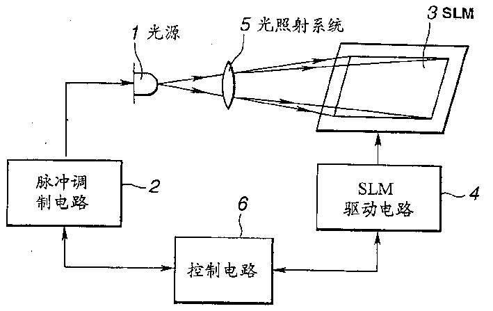
下面参照图4说明根据本发明的图像显示装置的第一实施例。该图像显示装置指定用作为TV接收机、计算机监视器、便携式终端等的显示装置。由图可看出,其包含:一发出光脉冲的光源1、一对来自光源1的光脉冲进行调制的脉冲调制电路2、一空间光调制器3,在其每一像素处对来自光源1的光脉冲进行调制、—用于驱动空间光调制器3的空间光调制器驱动电路4、—光照射用的光系统5,将来自光源1的光脉冲照射到空间光调制器3;—控制脉冲调制电路2和空间光调制器驱动电路4的控制电路6、—显示屏(在图4中未显示),由空间光调制器3调制的光投影到其上,以及一光投影用的光学系统(在图上未表示),将由空间光调制器3调制的光投影到显示屏上。Next, a first embodiment of an image display device according to the present invention will be described with reference to FIG. 4 . The image display device is intended for use as a display device for a TV receiver, a computer monitor, a portable terminal, and the like. As can be seen from the figure, it includes: a
为了利用图像显示装置显示图像,将图像的数据提供到控制电路6。控制电路6根据所提供的图像数据控制脉冲调节电路2和空间光调制器驱动电路4。脉冲调制电路2受控制电路6控制以驱动光源发出光脉冲。另一方面,由控制电路6控制空间光调制器驱动电路4,以便驱动空间光调制器4。In order to display an image by the image display device, data of the image is supplied to the
在脉冲调制电路2的控制之下,光源1如上所述发出光脉冲。更具体地说,来自光源1的光脉冲的宽度、数目等受脉冲调制电路2控制,后面将进一步讨论。应当认识到,光源1可以是卤族(元素)灯、金属卤化物灯、氙灯、发光二极管等。对于大屏幕的图像显示装置,卤族元素灯、金属卤化物灯、氙灯等是适用的,因为其能提供足够的光量。此外,对于要用于便携式终端的图像显示装置,发光二极管适于用作光源1,由于其能方便地满足较小屏幕和低功率消耗的要求。Under the control of the
为了显示彩色图像,光源1应当是能够发出与光的三基色相对应的红、绿和蓝色光脉冲,并且为了利用红、绿和蓝色光脉冲来显示图像应是分时的。对于与三基色对应的红、绿和蓝色光脉冲,可以对各自的颜色使用三种独立的光源。另外,可使用分色镜之类将来自一光源的光脉冲分离为红、绿和蓝色光脉冲。In order to display a color image, the
由光源1发出的光脉冲通过光照射用的光学系统5照射到空间光调制器3。在空间光调制器3中的每一像素处对光脉冲进行调制。这一空间光调制器3由能够快速工作的光调制材料例如FLC制成,在其中形成有众多像素。由驱动电路4驱动空间光调制器3,以便以双态方式对应于要显示的图像中的像素数据对在调制器3的每一像素处的光进行调节,在此之后,将由空间光调制器3在每一像素处调制的和反射的光通过该光投影用的光学系统投影到屏幕上,从而在屏幕上显示图像。The light pulse emitted from the
应指出,如前面所述的,空间光调制器3可以是反射型的或者是透射型的。反射型的空间光调制器可以设计成,将用于在空间光调制器的每一像素处驱动空间光调制器的存储元件之类配置在光反射表面相反的侧,存储元件不限制像素的有效口径。即在反射型空间光调制器中,每一像素的有效口径可以增加。另一方面,由于透射型空间光调制器可以省去光照射用的和光投影的光学系统,故图像显示装置可以设计成较薄结构。更具体地说,通过在透射型空间光调制器的背后处设置背照明以及利用出自背照明的并通过空间光调制器的光显示图像,可以使图像显示装置变得非常薄。It should be noted that, as previously mentioned, the spatial
根据本发明,在空间光调制器3中形成的像素的状态变化期间。光源1被关断,而当在空间光调制器3中形成的像素的状态稳定时,来自光源1的光脉冲照射到空间光调器3上。为了实现上述作用,如图4中所示,脉冲调节电路2连接到图像显示装置中的光源1上,使得由光源1发出的光脉冲由脉冲调制电路2来调制。然而,在本发明中,关断光源1意指来自光源1的光将不到达注视正显示的图像的人眼,也不是光源实际上必须关断。According to the invention, during the state change of the pixels formed in the spatial
为此,用作光开闭器的光调制器7可以配置在光源1和光照射用的光学系统5之间,代替脉冲调制电路2装设一开闭器驱动电路8以便控制光调制器7,如图5中所示。在这种情况下,光调制器7将由光源1发出的并入射到空间光调器3上的光形成为脉冲。通过利用由开闭器驱动电路8控制光调制器7的开闭时间,按照光脉冲的宽度、数目等控制照射到空间光调制器3的光脉冲。应指出,可以将机械式开闭器用作光调制器7,不过利用声光调制元件(AOM)无需机械操作的光调制器也适合于光调制器7。For this reason, an optical modulator 7 serving as an optical shutter can be arranged between the
下面,将讨论利用前述图像显示装置怎样利用渐变的光强来显示。应指出,在下文将“亮度级”将简称为“级”,并且每一像素的级数据为4比特。以举例的方式介绍按照16级的显示。In the following, it will be discussed how to use the aforementioned image display device to display with gradation of light intensity. It should be noted that "brightness level" will be simply referred to as "level" hereinafter, and the level data of each pixel is 4 bits. The display according to 16 levels is introduced by way of example.
在如下的介绍中,将需按照16级显示的一个图像的显示(周期)时间(period)取作为一个区段(field)。在常规的图像显示装置中,一个区段为16毫秒。具有16级的一个图像由至少四种光强彼此不同的图像组成。这样一种图像称之为“位面”。—个位面的显示(周期)时间称之为“子区段(sub-field)”。就是说,一个具有16种级的图像至少由4位面组成。当具有16种级的一个图像由4个位面组成时,一个区段由4个子区段组成。In the following introduction, the display (period) time (period) of an image to be displayed in 16 levels is taken as a field. In a conventional image display device, one segment is 16 milliseconds. One image with 16 levels is composed of at least four images whose light intensities are different from each other. Such an image is called a "plane". The display (period) time of one bit plane is called "sub-field". That is to say, an image with 16 levels consists of at least 4 bit planes. When one image with 16 levels is composed of 4 planes, one sector is composed of 4 sub-sectors.
为了显示具有16级的图像,如在图6中所示,在第一子区段SF1的时间内的时间点t首先显示第一位面BP1。接着,在第二子区段SF2的时间内的时间点t+SF1,显示第二位面BP2。然后,在第三子区段SF3的时间内的时间点t+SF1+SF2,显示第三位面BP3。接着,在第四子区段SF4的时间内的时间点t+SF1+SF2+SF3,显示第四位面BP4。在位面BP1到BP4显示之后,将再次按顺序显示下一图像中的各位面。To display an image with 16 levels, as shown in FIG. 6 , the first bit plane BP1 is first displayed at a point in time t within the time period of the first subfield SF1 . Next, at the time point t+SF1 within the second sub-section SF2, the second bit-plane BP2 is displayed. Then, at the time point t+SF1+SF2 within the time of the third sub-field SF3, the third bit-plane BP3 is displayed. Next, at the time point t+SF1+SF2+SF3 within the fourth sub-section SF4, the fourth bit-plane BP4 is displayed. After bit planes BP1 to BP4 are displayed, the respective planes in the next image will be displayed in order again.
现在假设,在各子区段之间的时间比SF1∶SF2∶SF3∶SF4=1∶2∶4∶8。因此,作为一个图像显示第一位面BP1,由人眼可识别的亮度级为1。对于第二、第三和第四位面,这些级分别为2、4和8。通过将这些位面重叠,可以按照16种级显示图像。即当连续显示这四个位面BP1、BP2、BP3和BP4时,在余象效应作用下,人眼可以按照16种级识别显示图像。It is now assumed that the time ratio SF1:SF2:SF3:SF4=1:2:4:8 between the individual subfields. Therefore, when the first bit plane BP1 is displayed as an image, the luminance level recognizable by human eyes is 1. For the second, third, and fourth planes, these levels are 2, 4, and 8, respectively. By overlapping these planes, images can be displayed in 16 levels. That is, when the four planes BP1, BP2, BP3 and BP4 are continuously displayed, under the afterimage effect, human eyes can recognize and display images according to 16 levels.
上面已经讨论了其中的一具有16级的图像由4位面组成的实例。然而,应当认识到一个具有16级的图像可以由五或更多的位面组成。即在上述实例中,一个区段被分成为4个子区段SF1、SF2、SF3和SF4,以及在每一子区段中显示位面BP1、BP2、BP3和BP4。如图7A中所示。然而,这些子区段和位面可以进一步进行再细分,如图7B和7C所示。应当指出,子区段和位面的数目以及子区段和位面的排列顺序并不限于如在图7A、7B和7C中所表示的上述实例中的那一些,而是可以自由地确定的。An example in which an image with 16 levels is composed of 4 bit planes has been discussed above. However, it should be realized that an image with 16 levels may be composed of five or more planes. That is, in the above example, one section is divided into four subsections SF1, SF2, SF3, and SF4, and bit planes BP1, BP2, BP3, and BP4 are displayed in each subsection. As shown in Figure 7A. However, these subsections and planes can be further subdivided, as shown in Figures 7B and 7C. It should be noted that the number of sub-sections and bit-planes and the arrangement order of sub-sections and bit-planes are not limited to those of the above-mentioned examples as shown in FIGS. 7A, 7B, and 7C, but can be freely determined. .
在图7B中所表示的实例中,第四位面进一步分成为位面BP4A和BP4B,第四子区段持续时间内显示第四位面BP4,该第四子区段细分为子区段,SF4A和SF4B。按照SF4A、SF1、SF2、SF3和SF4B的顺序排列各子区段,并且按照BP4A、BP1、BP2、BP3和BP4B的顺序显示各位面。In the example shown in FIG. 7B , the fourth bit plane is further divided into bit planes BP4A and BP4B, and a fourth bit plane BP4 is displayed for the duration of the fourth subsection, which is subdivided into subsections , SF4A and SF4B. The subsections are arranged in the order of SF4A, SF1, SF2, SF3, and SF4B, and the respective planes are displayed in the order of BP4A, BP1, BP2, BP3, and BP4B.
在图7C所示的实例中,第三位面BP3进一步分成为位面BP3A和BP3B,第四位面BP4进一步分成为位面BP4A和BP4B。此外,第三子区段SF3细分为子区段SF3A和SF3B,在第三子区段SF3的持续时间内显示位面BP3,以及第四子区段(在其持续时间内显示第四位面BP34)细分为子区段SF4A和SF4B。按SF4A、SF3A、SF1、SF2、SF3B和SF4B的顺序排列各子区段,而按BP4A、BP3A、BP1、BP2、BP3B和BP4B的顺序显示各位面。In the example shown in FIG. 7C , the third bit-plane BP3 is further divided into bit-planes BP3A and BP3B, and the fourth bit-plane BP4 is further divided into bit-planes BP4A and BP4B. Furthermore, the third sub-section SF3 is subdivided into sub-sections SF3A and SF3B, showing bit-plane BP3 for the duration of the third sub-section SF3, and a fourth sub-section (showing the fourth bit-plane Surface BP34) is subdivided into subsections SF4A and SF4B. The subfields are arranged in the order of SF4A, SF3A, SF1, SF2, SF3B, and SF4B, while the planes are displayed in the order of BP4A, BP3A, BP1, BP2, BP3B, and BP4B.
按常规为了按渐变的光强显示,如上所述,光源总是按照预定的光强维持发光,以高速驱动空间光调制器,以便调节每一位面的光强,即每一位面的显示时间。与之对比,根据本发明,由光源1所发出的光呈脉冲状并进行脉冲调制以便调制光强。下面将详细讨论来自光源1的光怎样形成脉冲以及怎样作为图像显示。Conventionally, in order to display according to the gradual light intensity, as mentioned above, the light source always maintains light according to the predetermined light intensity, and the spatial light modulator is driven at high speed, so as to adjust the light intensity of each plane, that is, the display of each plane time. In contrast, according to the present invention, the light emitted by the
根据本发明,在像素状态变化期间关断光源,而仅当像素状态稳定时接通。这一点表示在图8中。在这一实例中,空间光调制器3为反射型,其利用具有状态存储特性的光调制材料。即当重新写入像素时只要施加驱动电压就够了以及其后即使使驱动电压为零也能维持像素状态。According to the invention, the light source is switched off during pixel state changes and switched on only when the pixel state is stable. This is shown in Figure 8. In this example, the spatial
在图8中所示的时间关系图中,以举例的方式表示两个像素m和n。图8表示由光源发出的光、施加到空间光调制器3以改变像素m的状态的驱动电压、施加到空间光调制器3以改变像素n的状态的驱动电压、空间光调制器3中关于像素m的部分的状态、空间光调制器3中关于像素n的部分的状态、由空间光调制器3中的像素m反射的光、由空间光调制器3中的像素n反射的光等量的随时间变化。In the time diagram shown in FIG. 8, two pixels m and n are represented by way of example. 8 shows the light emitted by the light source, the driving voltage applied to the spatial
由图8可以看出,在该像素m和n的状态变化的时间(过渡时间)段光源1被关断。仅对于所有像素m和n均处于稳定状态的时间段(状态稳定的时间)才接通光源1。It can be seen from FIG. 8 that the
通常,空间光调制器中的所有像素的特性是不均匀的,它们的响应特性由一个区域到另一个区域的平面内是变化的。因此,如果空间光调制器对其中的不同像素m和n施加相同的驱动电压,像素m和n很可能以不同的方式响应,这种情况是可能产生的。即,即使像素m和n被施加相同的驱动电压,它们很可能彼此呈现不同的状态。因此,当在过渡时间段中显示图像时,将产生光强不均匀性。Typically, the characteristics of all pixels in a spatial light modulator are non-uniform, and their response characteristics vary in-plane from one region to another. Therefore, if the same driving voltage is applied to different pixels m and n in the spatial light modulator, it is likely that the pixels m and n will respond in different ways, and this situation may arise. That is, even if the pixels m and n are applied with the same driving voltage, they are likely to assume different states from each other. Therefore, when an image is displayed during the transition period, light intensity non-uniformity will be generated.
根据本发明,对于过渡时间(段)关断光源1,使得不显示图像。因此,即使在过渡时间段中像素m以与像素n不同的方式响应,这样的差别也不会对图像显示有影响。因此,即使在空间光调制器3中产生平面内的特性变化,仍可显示一无光强不均匀和具有优异质量的图像。According to the invention, the
进而,根据本发明,仅当像素状态稳定时,才能对照射到空间光调制器3上的光脉冲进行调制,以便按照很多级进行显示。下面参照本发明的8个实施例介绍脉冲调制。Furthermore, according to the present invention, only when the pixel state is stable, the light pulses irradiated on the spatial
应当认识到在如下的实施例中,为了按照16级显示将采用上述四位面BP1、BP2、BP3和BP4。就是说,在第一子区段SF1的持续时间内显示第一位面BP1,其中由人眼可识别的亮度级为1。在第二子区段SF2的持续时间内显示第二位面BP2,其中由人眼可识别的亮度级为2。在第三子区段SF3的持续时间内显示第三位面BP3,其中的由人眼可识别的亮度级为4。在第四子区段SF4的持续时间内显示第四位面BP4,其中的由人眼可识别的亮度级为8。It should be appreciated that in the following embodiments, the above-mentioned four-bit planes BP1, BP2, BP3, and BP4 will be used for displaying in 16 levels. This means that the first bit plane BP1 is displayed for the duration of the first subfield SF1 , with a brightness level of 1 recognizable by the human eye. The second bit plane BP2 is displayed for the duration of the second subfield SF2 , with a brightness level of 2 recognizable by the human eye. The third bit plane BP3 is displayed for the duration of the third sub-field SF3 , in which the
此外在下面进一步讨论的本发明的各实施例中,将介绍按照16个亮度级的显示,这一级数目是相对小的。然而,本发明当然可以按照或多或少的级进行显示。特别是,本发明的优点在于,按照增加的级数目即使空间光调制器不能快速响应也可以显示图像。例如,对于空间光调制器3中的每一像素可以指定8比特的级数据,以便按256个级显示图像。此外,对于每个像素可以指定10(这样的)位,以便按照1024个级显示图像。这些都是易于实现的。Furthermore, in the embodiments of the invention discussed further below, a display in terms of 16 brightness levels will be described, which is a relatively small number of levels. However, the invention can of course be shown in more or less stages. In particular, the present invention is advantageous in that an image can be displayed according to the increased number of stages even if the spatial light modulator cannot respond quickly. For example, 8-bit level data can be specified for each pixel in the spatial
在如下的实施例中,为了介绍和表示简化,针对具有16个级的一个图像中的四个位面。然而,还应当认识到,根据本发明,具有16个级的一个图像当然可以由5个或更多个位面组成,如图7中所示。In the following embodiments, for simplicity of presentation and presentation, four bit planes in one image with 16 levels are targeted. However, it should also be realized that an image with 16 levels may of course be composed of 5 or more bit planes according to the present invention, as shown in FIG. 7 .
第一实施例first embodiment
根据这一实施例,所有的子区段确定具有相同的时间长度,并对来自光源的光脉冲进行脉宽调制,如图9中所示。According to this embodiment, all sub-segments are determined to have the same time length and pulse-width modulate the light pulses from the light source, as shown in FIG. 9 .
还应当指出,利用在图像显示装置中的脉冲调制电路2按预定的时间控制光源1的接通和关断,从而调制光脉冲,如图10所示。此外,在图6中所示的图像显示装置中,通过利用开闭器驱动电路8控制光调制器7按时通断,实现光脉冲调制。对于第二到第七实施例上述情况也是正确的,接着对第一实施例的解释将介绍第二到第七实施例。It should also be noted that the
如图9中所示,在第一实施例中,在每一子区段的延续时间内来自光源1的经调制以具有与每一位面相对应的宽度的光脉冲照射到空间光调制器3。即,对于第一子区段SF1,对照射到空间光调制器3上的光脉冲调制使之具有的宽度为t。对于第二子区段SF2照射的光脉冲的脉冲宽度为2×t,对于第三子区段照射的光脉冲的脉冲宽度为4×t,对于第四子区段SF4则为8×t。As shown in FIG. 9, in the first embodiment, a light pulse modulated from the
由于上述调制的结果,由人眼可识别的第一位面BP1的级为1,对第二位面BP2则为2,对第三位面BP3为4,对第四位面为8。如前所述,将这些位面BP1、BP2、BP3和BP4彼此重叠,以便按16个级显示图像。As a result of the above modulation, the level of the first bit plane BP1 recognized by human eyes is 1, the level of the second bit plane BP2 is 2, the level of the third bit plane BP3 is 4, and the level of the fourth bit plane is 8. As described above, these bit planes BP1, BP2, BP3, and BP4 are superimposed on each other to display images in 16 gradations.
为了增加用于显示图像的级的数目,需要增加对于一个区段显示的位面的数目。在常规的图像显示装置中为实现相同的目的,应降低子区段的时间以增加位面数目。然而,由于空间光调制器的响应速度是受限制的,降低子区段时间也会受到限制。因此,在常规的图像显示装置中难于增加用于图像显示的级的数目。In order to increase the number of levels for displaying images, it is necessary to increase the number of bit planes displayed for one sector. To achieve the same purpose in a conventional image display device, the sub-segment time should be reduced to increase the number of bit planes. However, since the response speed of the spatial light modulator is limited, reducing the sub-segment time is also limited. Therefore, it is difficult to increase the number of stages for image display in conventional image display devices.
另一方面,根据这一实施例,调制光脉冲以改变每一位面的级,与子区段的时间长度无关。因此,即使当为了在光调制器3的正常工作,要保证子区段时间长度足够长,也能够增加亮度级不同的位面的数目。因此,根据本发明,能够按照比以经更多的级显示图像。On the other hand, according to this embodiment, the light pulses are modulated to change the level of each bit plane independently of the temporal length of the sub-segments. Therefore, even when the sub-segment time length is ensured to be sufficiently long for normal operation of the
第二实施例second embodiment
根据这一实施例,而在对来自光源1的光脉冲进行脉宽调节时,子区段的时间是变化的,如图10所示。According to this embodiment, when the pulse width of the light pulse from the
更具体地说,第一子区段SF1和第二子区段SF2的时间确定为t1,第三子区段SF3和第四子区段的时间确定为2×t1,即为第一和第二子区段SF1和SF2的时间2倍长。在这些长度不同的时间范围内,经调制以使宽度对应于每一位面的光脉冲由光源1照射到空间光调制器3上。More specifically, the time of the first sub-section SF1 and the second sub-section SF2 is determined as t1, and the time of the third sub-section SF3 and the fourth sub-section is determined as 2×t1, that is, the first and second sub-sections The time of the two sub-fields SF1 and SF2 is twice as long. In these time ranges of different lengths, light pulses modulated to have a width corresponding to each bit plane are irradiated from the
此外,对于第一子区段SF1,对照射到空间光调制器3上的光脉冲进行调制,使其宽度为t。对于第二子区段SF2,经调制宽度为2×t。对于第三子区段SF3,经调制宽度为4×t。对于第四子区段SF4,经调制宽度为8×t。In addition, for the first sub-section SF1, the light pulse irradiated on the spatial
由于进行上述调制的结果,由人眼可识别的第一位面BP1的级为1,第二位面BP2为2,第三位面BP3为4,第四位面为8。正如前面已介绍的,通过将各位面BP1到BP4彼此重叠,按16种级显示图像。As a result of the above modulation, the level of the first bit plane BP1 recognized by human eyes is 1, the second bit plane BP2 is 2, the third bit plane BP3 is 4, and the fourth bit plane is 8. As described earlier, by overlapping the respective planes BP1 to BP4 with each other, images are displayed in 16 gradations.
如图10中所示,子区段的时间长度是变化的,以便降低由光源1照射较小宽度的光脉冲的位面的光源的关断时间,因此,使得能够以较高的效率利用光。由于降低了关断时间,可以抑制由于来自光源1的光的脉冲引起的图像闪烁。As shown in FIG. 10 , the time length of the sub-segments is varied in order to reduce the off-time of the light source of the bit plane irradiated by the
应注意,在各子区段之间的时间长度之比并不限于上述实例,而是可以自由确定。It should be noted that the ratio of the time lengths between the respective sub-sections is not limited to the above example, but can be freely determined.
第三实施例third embodiment
根据这一实施例,确定所有的子区段。使之具有相同的时间长度,对来自光源1的光脉冲进行脉宽调制,由光源1对于一个子区段发出二个光脉冲,如图11所示。即根据本发明,由光源1向空间光调制器3发出两个经调制的光脉冲,使得其宽度对应于在每一子区段的时间内的各位面。According to this embodiment, all subsections are determined. To make it have the same time length, pulse width modulation is performed on the light pulse from the
更具体地说,对于第一子区段SF1,在两个时间点按照预定的间隔,宽度为t/2的光脉冲照射到空间光调制器3上,如图11所示。对于第二子区段SF2,宽度为t的光脉冲按照预定的间隔两次照射到空间光调制器3上。对于第三子区段SF3,宽度为2×t的光脉冲按照预定的间隔两次照射到空间光调制器3上。对于第四子区段SF4,宽度为4×t的光脉冲按照预定的间隔两次照射到空间光调制器3上。More specifically, for the first sub-section SF1 , light pulses with a width of t/2 are irradiated onto the spatial
由于进行上述脉冲调制的结果,由人眼可识别的第一位面BP1的级为1。对于第二位面BP2为2,对于第三位面BP3为4,对于第四位面BP4为8。如前面已介绍的,通过将各位面BP1到PB4彼此重叠,可按16种级显示图像。As a result of performing the above pulse modulation, the level of the first bit plane BP1 recognizable by human eyes is 1. It is 2 for the second bit plane BP2, 4 for the third bit plane BP3, and 8 for the fourth bit plane BP4. As already described, by overlapping the respective planes BP1 to PB4 with each other, images can be displayed in 16 gradations.
如图11中所示,在一个子区段时间内光脉冲一次之上照射到空间光调制器3上,以便降低光源1被持续关断的时间,因此,可以有效地利用子区段时间。由于持续关断的时间降低,可以抑制由于来自光源1的光的脉动所引起的图像闪烁。As shown in FIG. 11 , the light pulse is irradiated onto the spatial
在图11所示的实施例中,在一个子区段时间内两次发出光脉冲。然而,应当认识到,如果按照足够高的速度接通和关断光源1,在一个子区段时间内可以三次以上发出光脉冲。In the embodiment shown in FIG. 11, light pulses are emitted twice within a sub-segment time. However, it should be realized that if the
第四实施例Fourth embodiment
根据这一实施例,确定所有的子区段使之具有相同的时间,在如图12的每一个子区段的时间内改变照射到空间光调制器3的光脉冲数。According to this embodiment, all sub-sections are determined to have the same time, and the number of light pulses irradiated to the spatial
更具体地说,对于第一子区段SF1,宽度为t的光脉冲一次照射到空间光调制器3上。对于第二子区段SF2,宽度为t的光脉冲按预定的间隔四次两次照射。对于第三子区段SF3,宽度为t的光脉冲按预定的间隔照射。对于第四子区段SF4,宽度为t的光脉冲按预定的间隔八次照射。More specifically, for the first sub-section SF1, a light pulse with a width t is irradiated onto the spatial
由于进行上述脉冲调制的结果,由人眼可识别的位面BP1的级为1。对于位面BP2为2,对于位面BP3为4,对于位面BP4为8。正如上文所介绍的,通过将各位面BP1到BP4彼此重叠,可按16个级显示图像。As a result of performing the above pulse modulation, the level of the bit plane BP1 recognizable by human eyes is 1. 2 for bitplane BP2, 4 for bitplane BP3, and 8 for bitplane BP4. As described above, by overlapping the respective planes BP1 to BP4 with each other, images can be displayed in 16 steps.
在这一第四实施例和下面将讨论的第五到第八实施例中,在一个区段时间内改变脉冲的数目,而脉冲宽度保持不变。这种脉冲调制的优点是能比脉宽调制更精确地调制。In this fourth embodiment and the fifth to eighth embodiments to be discussed below, the number of pulses is changed within a segment time while the pulse width remains constant. The advantage of this pulse modulation is that it can be modulated more precisely than pulse width modulation.
第五实施例fifth embodiment
根据这一实施例,子区段时间是变化的,同时对于每一子区段时间照射到空间光调制器上的光脉冲数目是变化的,如图13中所示。According to this embodiment, the sub-segment time is varied, as is the number of light pulses impinging on the spatial light modulator for each sub-segment time, as shown in FIG. 13 .
就是说,第一和第二子区段SF1和SF2的时间确定为t1,第三和第四子区段SF3和SF4的时间确定为2×t1,即为第一和第二子区段SF1和SF2的时间的2倍。对于每一子区段时间,由光源1照射到空间光调制器3上的光脉冲的数目是变化的。That is to say, the time of the first and second sub-sections SF1 and SF2 is determined as t1, and the time of the third and fourth sub-sections SF3 and SF4 is determined as 2×t1, that is, the first and second sub-sections SF1 and 2 times the time of SF2. For each sub-segment time, the number of light pulses irradiated by the
更具体地说,对于第一子区段SF1,宽度为t的光脉冲一次照射到空间光调制器3上。对于第二子区段SF2,宽度为t的光脉冲按预定的间隔两次照射到空间光调制器3上。对于第三子区段SF3,宽度为t的光脉冲4次照射到空间光调制器3上。对于第四子区段SF4,宽度为t的光脉冲按预定的间隔8次照射到空间光调制器3上。More specifically, for the first sub-section SF1, a light pulse with a width t is irradiated onto the spatial
由于进行上述脉冲调制的结果,由人眼可识别的第一位面BP1的级为1,对于第二位面BP2为2,对于第三位面BP3为4,对于第四位面BP4为8。如上所述,将这些位面BP1、BP2、BP3和BP4彼此重叠,以按照16种级显示图像。As a result of the above-mentioned pulse modulation, the level of the first bit-plane BP1 recognizable by human eyes is 1, the level of the second bit-plane BP2 is 2, the level of the third bit-plane BP3 is 4, and the level of the fourth bit-plane BP4 is 8 . As described above, these bit planes BP1, BP2, BP3, and BP4 are superimposed on each other to display images in 16 gradations.
如图13中所示,子区段的长度是变化的,以对于由光源1照射较少数目的光脉冲的一位面降低光源关断时间,因此,使得能以更高的效率利用光。由于来自光源1的光的脉冲引起的图像闪烁可以得到抑制。As shown in Figure 13, the length of the sub-sections is varied to reduce the light source off-time for a plane illuminated by the
应注意,在各子区段之间的时间长度比并不局限于上述的实例,而是可以自由确定。It should be noted that the time length ratio between the respective sub-sections is not limited to the above example, but can be freely determined.
第六实施例Sixth embodiment
根据这一实施例,所有的子区段具有相同时间长度,设想将子区段时间除以2,对于各子区段分别按照不同数目的光脉冲照射空间光调制器,如图14所示。应注意,对子区段的除法运算的除数并不局限为2,而是可以自由确定。According to this embodiment, all sub-segments have the same time length, imagine dividing the sub-segment time by 2, and irradiating the spatial light modulator with different numbers of light pulses for each sub-segment, as shown in FIG. 14 . It should be noted that the divisor of the division operation on the subsections is not limited to 2, but can be freely determined.
根据这一实施例,对于第一子区段SF1的前半部,宽度为t/2的光脉冲一次照射到空间光调制器3上。对于后半部,宽度为t/2的光脉冲一次照射到空间光调制器3上。对于第二子区段SF2的前半部,宽度为t/2的光脉冲两次照射到空间光调制器3上,对于后半部,宽度为t/2的光脉冲两次照射到空间光调制器3上。对于第三子区段SF3的前半部,宽度为t/2的光脉冲4次照射到空间光调制器3上,对于后半部宽度为t/2的光脉冲4次照射到空间光调制器3上。对于第四子区段SF4的前半部,宽度为t/2的光脉冲8次照射到空间光调制器3上,对于第四子区段SF4的后半部,宽度为t/2的光脉冲8次照射到空间光调制器上。According to this embodiment, for the first half of the first sub-field SF1, a light pulse of width t/2 is irradiated onto the spatial
由于进行上述脉冲调制的结果,由人眼可识别的第一位面BP1的级为1,对于第二、三、四位面BP2、BP3和BP4,由人眼可识别的级分别为2、4和8。通过将这些位面BP1和BP4彼此重叠,可按16种级显示图像。As a result of the above-mentioned pulse modulation, the level of the first plane BP1 recognizable by human eyes is 1, and for the second, third and fourth planes BP2, BP3 and BP4, the levels recognizable by human eyes are respectively 2, 4 and 8. By overlapping these bit planes BP1 and BP4 with each other, images can be displayed in 16 gradations.
如图14所示,一个子区段再细分为多个子区段,预定数目的光脉冲照射到每个再细分的子区段,使得光源1被持续关断的时间可以降低,因此可以更有效地利用光。由于降低关断时间,可以抑制由于来自光源1的光的脉动所引起的图像闪烁。As shown in Figure 14, a sub-section is subdivided into a plurality of sub-sections, and a predetermined number of light pulses are irradiated to each sub-section, so that the time that the
第七实施例Seventh embodiment
根据这一实施,所有的子区段具有相同的时间长度,对于每一子区段时间,照射到空间光调制器3上的光脉冲的数目是变化的,如图15所示。在子区段时间范围内,在近于均匀分布的时间点发出光脉冲。According to this implementation, all sub-segments have the same time length, and for each sub-segment time, the number of light pulses irradiated on the spatial
根据本发明的第七实施例,所有的子区段的时间都具有预定的长度。由一时间点到另一时间点的时间确定为t,在前一时间点,空间光调制器3中的每一像素的状态达到稳定,在后一时间点,空间光调制器3中的每一像素的状态开始改变,即在一时间点上下一个位面开始。应当认识到,如果在空间光调制器3达到稳定以后,在一子区段开始后实现光脉冲的第一(次)照射,则时间t可以与子区段时间相同。According to the seventh embodiment of the present invention, the times of all the sub-sections have a predetermined length. The time from one time point to another time point is determined as t, at the previous time point, the state of each pixel in the spatial
在空间光调制器3中的每个像素达到稳定以及第一位面BP1显示在空间光调制器3上的时间确定为S1,在空间光调制器3中的每个像素达到稳定以及第二位面BP2显示在空间调制器3上的时间点确定为S2,在空间光调制器3中的每个像素达到稳定以及第三位面BP3显示在空间光调制器3上的时间点确定为S3,在空间光调制器3中的每个像素达到稳定以及第四位面BP4显示在空间光调制器3上的时间点确定为S4。The time at which each pixel in the spatial
根据第七实施例,对于第一子区段SF1,宽度为t/2的光脉冲2次照射到空间光调制器3上。在时间点S1+t/3以及在时间点S1+2×t/3分别照射光脉冲。According to the seventh embodiment, for the first subfield SF1 , a light pulse with a width of t/2 is irradiated onto the spatial
对于第二子区段SF2,宽度为t/2的光脉冲4次照射到空间光调制器3上。在时间点S2+t/5,在时间点S2+2×t/5,在时间点S2+3×t/5以及在时间点S2+4×t/5分别照射光脉冲。For the second sub-section SF2 , the light pulse with a width of t/2 is irradiated onto the spatial
对于第三子区段SF3,宽度为t/2的光脉冲8次照射到空间光调制器3上。在时间点S3+t/9、在时间点S3+2×t/9,在时间点S3+3×t/9,在时间点S3+4×t/9,在时间点S3+5×t/9,在时间由S3+6×t/9,在时间点S3+7×t/9,在时间点S3+8×t/9分别照射光脉冲。For the third sub-section SF3, the light pulse with a width of t/2 is irradiated on the spatial
对于第四子区段SF4,宽度为t/2的光脉冲16次照射空间光调制器3。在时间点S4+t/17,在时间点S4+2×t/17,在时间点S4+3×t/17,在时间点S4+4×t/17,在时间点S4+5×t/17,在时间点S4+6×t/17,在时间点S4+7×t/17,在时间点S4+8×t/17,在时间点S4+9×t/17,在时间点S4+10×t/17,在时间点S4+11×t/17,在时间点S4+12×t/17,在时间点S4+13×t/17,在时间点S4+14×t/17,在时间点S4+15×t/17,在时间点S4+16×t/17分别照射光脉冲。For the fourth subfield SF4, the spatial
由于进行上述脉冲调制的结果,由人眼可识别的第一位面BP1的级为1,对于第二位面BP2的级为2,对于第三位面BP3的级为4,对于第四位面BP4的级为8。如先前所介绍的,通过将各位面彼此重叠,可按16种级显示图像。As a result of the above-mentioned pulse modulation, the level of the first bit plane BP1 recognizable by human eyes is 1, the level of the second bit plane BP2 is 2, the level of the third bit plane BP3 is 4, and the level of the fourth bit plane BP3 is 4. The level of face BP4 is 8. As described earlier, by overlapping each plane, images can be displayed in 16 gradations.
如图15中所示,根据本发明,在整个子区段时间范围内,在近于均匀分布的各时间点发出光脉冲以降低光源1持续关断的时间,因此可以有效地利用了区段时间。由于降低了持续关断的时间,可以抑制由于来自光源1的光的脉动引起的图像闪烁。As shown in FIG. 15, according to the present invention, within the time range of the entire sub-section, light pulses are emitted at each time point that is nearly uniformly distributed to reduce the time that the
第八实施例Eighth embodiment
根据这一实施例,子区段时间的长度是变化的,同时对于第一子区段时间,照射到空间光脉冲的数目也是变化的,如图16所示。此外,在整个子区段时间范围内,在近于均匀分布的各时间点发出光脉冲。According to this embodiment, the length of the sub-segment time is varied, and at the same time, the number of the spatial light pulses irradiated to the first sub-segment time is also varied, as shown in FIG. 16 . In addition, light pulses are emitted at approximately uniformly distributed time points over the entire sub-segment time range.
下面假设第一和第二子区段SF1和SF2的时间为t,对第三和第四子区段的时间则为2×t。此外,假设在一时间点S1,空间光调制器3中的每一像素达到稳定以及第一位面BP1显示在空间光调制器3上。此外假设在一时间点S2,空间光调制器3中的每一像素的状态达到稳定并在空间光调制器3上显示第一位面BP2。另外,假设在时间点S3,空间光调制器3上的每一像素的状态达到稳定并在空间光调制器3上显示第一位面BP3。还假设在时间点S4,空间光调制器3中的每一像素达到稳定状态并在空间光调制器3上显示第一位面BP4。In the following it is assumed that the time is t for the first and second sub-fields SF1 and SF2, and 2*t for the third and fourth sub-field. Furthermore, assume that at a time point S1 , each pixel in the
应注意,在各子区段之间的时间比并不局限于上述值,而是可以自由确定。It should be noted that the time ratio between the respective sub-sections is not limited to the above-mentioned values, but can be freely determined.
如果在上述相同的假设条件下,在空间光调制器3的过渡过程中照射第一光脉冲,在第一和第二子区段SF1和SF2的时间内,空间光调制器3的稳定状态的时间长度最好应为t,而在第三和第四子区段SF3和SF4的时间内的对应值最好为2×t。If the first light pulse is irradiated during the transition of the spatial
根据这一实施例,对于第一子区段SF1,宽度为t/2的光脉冲两次照射到空间光调制器3上。在时间点S1+t/3,在时间点S1+2×t/3分别照射光脉冲。According to this embodiment, for the first subfield SF1 a light pulse of width t/2 impinges on the spatial
对于第二子区段SF2,宽度为t/2的光脉冲4次照射到空间光调制器3上。在时间点S2+t/5,在时间点S2+2×t/5,在时间点S2+3×t/5,在时间点S2+4×t/5分别照射光脉冲。For the second sub-section SF2 , the light pulse with a width of t/2 is irradiated onto the spatial
对于第三子区段SF3,宽度为t/2的光脉冲8次照射到空间光调制器3上。在时间点S3+2×t/9,在时间点S3+4×t/9,在时间点S3+6×t/9,在时间点S3+8×t/9,在时间点S3+10×t/9,在时间点S3+12×t/9,在时间点S3+14×t/9,在时间点S3+16×t/9分别照射光脉冲。For the third sub-section SF3, the light pulse with a width of t/2 is irradiated on the spatial
对于第四子区段SF4,宽度为t/2的光脉冲16次照射到空间光调制器3上。在时间点S4+2×t/17,在时间点S4+4×t/17,在时间点S4+6×t/17,在时间点S4+8×t/17,在时间点S4+10×t/17,在时间点S4+12×t/17,在时间点S4+14×t/17,在时间点S4+16×t/17,在时间点S4+18×t/17,在时间点S4+20×t/17,在时间点S4+22×t/17,在时间点S4+24×t/17,在时间点S4+26×t/17,在时间点S4+28×t/17,在时间点S4+30×t/17,在时间点S4+32×t/17分别照射脉冲。For the fourth sub-section SF4 , light pulses with a width of t/2 are irradiated onto the spatial
由于进行上述脉冲调制的结果,由人眼可识别的第一位面BP1的级为1,对于第二位面BP2为2,对于第三位面BP3为4,对于第四位面BP4为8。正如前面已经介绍的,通过将各位面BP1到BP4彼此重叠可按照16种级显示图像。As a result of the above-mentioned pulse modulation, the level of the first bit-plane BP1 recognizable by human eyes is 1, the level of the second bit-plane BP2 is 2, the level of the third bit-plane BP3 is 4, and the level of the fourth bit-plane BP4 is 8 . As has been described earlier, images can be displayed in 16 gradations by overlapping the respective planes BP1 to BP4 with each other.
如图16所示,子区段的长度是变化的,以降低对于由光源1照射较小数目的脉冲的位面的光源的关断时间,因此使得能够以较高的效率利用光。由于降低了关断时间,可以抑制由于来自光源1的光的脉动引起的图像闪烁。As shown in Figure 16, the length of the sub-sections is varied to reduce the off-time of the light source for the planes illuminated by the
上面已参照本发明的第一到第八实施例进行了介绍,在没有高速驱动空间光调制器3的情况下,可以由光源1发出经调制的光脉冲,按很多级显示图像。在常规的图像显示装置中,要高速驱动空间光调制器3,以改变对于每一位面的子区段时间,以便按照很多级显示图像。然而,由于空间光调制器3的高响应速度是受到限制的,子区段时间不可能充分降低。使得通过增加级数目显示图像是极为困难的。与之对比,由于在根据本发明的图像显示装置和方法中,对由光源1发出的光进行调制,即使当为了空间光调制3的正常工作要保证足够长的子区段时间时,也可以易于增加位面的数目,达到更多的级。As described above with reference to the first to eighth embodiments of the present invention, without driving the spatial
由对本发明的以上介绍可以看出,即使利用进行双态的光调制的空间光调制器,本发明也能按照足够数目的级来显示图像。由于在像素状态变化的过渡时间的过程中光源是关断的,即使当空间光调制器的特性平面内变化时,图像也具有优异的质量而无光强不均匀的现象。From the above description of the present invention, it can be seen that even with a spatial light modulator that performs binary light modulation, the present invention can display images in a sufficient number of levels. Since the light source is turned off during the transition time of the pixel state change, even when the characteristic of the spatial light modulator changes in-plane, the image has excellent quality without unevenness of light intensity.
Claims (16)
Applications Claiming Priority (3)
| Application Number | Priority Date | Filing Date | Title |
|---|---|---|---|
| JP17738797A JP3840746B2 (en) | 1997-07-02 | 1997-07-02 | Image display device and image display method |
| JP177387/97 | 1997-07-02 | ||
| JP177387/1997 | 1997-07-02 |
Publications (2)
| Publication Number | Publication Date |
|---|---|
| CN1211024A CN1211024A (en) | 1999-03-17 |
| CN1150503C true CN1150503C (en) | 2004-05-19 |
Family
ID=16030058
Family Applications (1)
| Application Number | Title | Priority Date | Filing Date |
|---|---|---|---|
| CNB981033768A Expired - Lifetime CN1150503C (en) | 1997-07-02 | 1998-07-02 | Image display device and method |
Country Status (5)
| Country | Link |
|---|---|
| US (1) | US6008929A (en) |
| EP (1) | EP0889458A3 (en) |
| JP (1) | JP3840746B2 (en) |
| KR (1) | KR100865325B1 (en) |
| CN (1) | CN1150503C (en) |
Cited By (1)
| Publication number | Priority date | Publication date | Assignee | Title |
|---|---|---|---|---|
| US8405690B2 (en) | 2006-06-02 | 2013-03-26 | Compound Photonics Limited | Optically addressed gray scale electric charge-accumulating spatial light modulator |
Families Citing this family (87)
| Publication number | Priority date | Publication date | Assignee | Title |
|---|---|---|---|---|
| US20030107539A1 (en) * | 1995-01-31 | 2003-06-12 | Wood Lawson A. | Display apparatus and method |
| US7253794B2 (en) * | 1995-01-31 | 2007-08-07 | Acacia Patent Acquisition Corporation | Display apparatus and method |
| KR20010050623A (en) * | 1999-10-04 | 2001-06-15 | 모리시타 요이찌 | Display technique for high gradation degree |
| JP2001125547A (en) * | 1999-10-28 | 2001-05-11 | Sony Corp | Liquid crystal display device and display method thereof |
| US6559827B1 (en) | 2000-08-16 | 2003-05-06 | Gateway, Inc. | Display assembly |
| US7034801B2 (en) | 2001-01-10 | 2006-04-25 | Mitsubishi Denki Kabushiki Kaisha | Color image display |
| US20040027362A1 (en) * | 2001-06-27 | 2004-02-12 | Hiroaki Sato | Color image displaying method and apparatus |
| US6621615B2 (en) * | 2001-07-25 | 2003-09-16 | Eastman Kodak Company | Method and system for image display |
| US7064740B2 (en) | 2001-11-09 | 2006-06-20 | Sharp Laboratories Of America, Inc. | Backlit display with improved dynamic range |
| AU2003206029A1 (en) * | 2002-03-20 | 2003-09-29 | Koninklijke Philips Electronics N.V. | Method of driving a foil display screen and device having such a display screen |
| US7417782B2 (en) | 2005-02-23 | 2008-08-26 | Pixtronix, Incorporated | Methods and apparatus for spatial light modulation |
| US7142186B2 (en) * | 2003-03-24 | 2006-11-28 | Hivix Co., Ltd | Method and apparatus for converting gradation data in STN LCD |
| JP2004354717A (en) * | 2003-05-29 | 2004-12-16 | Seiko Epson Corp | Display device and projection display device |
| WO2005005121A2 (en) * | 2003-07-11 | 2005-01-20 | Koninklijke Philips Electronics N.V. | A method of manufacturing a mould for producing an optical surface, a method of producing a contact lens and a device for use with these methods |
| US7948505B2 (en) * | 2003-11-01 | 2011-05-24 | Silicon Quest Kabushiki-Kaisha | Method for reducing temporal artifacts in digital video systems |
| US8157389B2 (en) * | 2003-11-01 | 2012-04-17 | Silicon Quest Kabushiki-Kaisha | Synchronous control system for light source and spatial light modulator employed in projection apparatus |
| US7817330B2 (en) * | 2003-11-01 | 2010-10-19 | Silicon Quest Kabushiki-Kaisha | Projection apparatus with adjustable light source |
| US7623105B2 (en) | 2003-11-21 | 2009-11-24 | Sharp Laboratories Of America, Inc. | Liquid crystal display with adaptive color |
| US8395577B2 (en) | 2004-05-04 | 2013-03-12 | Sharp Laboratories Of America, Inc. | Liquid crystal display with illumination control |
| US7872631B2 (en) | 2004-05-04 | 2011-01-18 | Sharp Laboratories Of America, Inc. | Liquid crystal display with temporal black point |
| US7505018B2 (en) | 2004-05-04 | 2009-03-17 | Sharp Laboratories Of America, Inc. | Liquid crystal display with reduced black level insertion |
| US7602369B2 (en) | 2004-05-04 | 2009-10-13 | Sharp Laboratories Of America, Inc. | Liquid crystal display with colored backlight |
| US7612757B2 (en) | 2004-05-04 | 2009-11-03 | Sharp Laboratories Of America, Inc. | Liquid crystal display with modulated black point |
| US7532192B2 (en) | 2004-05-04 | 2009-05-12 | Sharp Laboratories Of America, Inc. | Liquid crystal display with filtered black point |
| US7777714B2 (en) | 2004-05-04 | 2010-08-17 | Sharp Laboratories Of America, Inc. | Liquid crystal display with adaptive width |
| US7023451B2 (en) | 2004-06-14 | 2006-04-04 | Sharp Laboratories Of America, Inc. | System for reducing crosstalk |
| US7556836B2 (en) | 2004-09-03 | 2009-07-07 | Solae, Llc | High protein snack product |
| US7564874B2 (en) * | 2004-09-17 | 2009-07-21 | Uni-Pixel Displays, Inc. | Enhanced bandwidth data encoding method |
| US7898519B2 (en) | 2005-02-17 | 2011-03-01 | Sharp Laboratories Of America, Inc. | Method for overdriving a backlit display |
| US8050511B2 (en) | 2004-11-16 | 2011-11-01 | Sharp Laboratories Of America, Inc. | High dynamic range images from low dynamic range images |
| KR100632540B1 (en) * | 2004-11-16 | 2006-10-09 | 삼성전기주식회사 | Scanning apparatus using a light source that operates on and off |
| US8050512B2 (en) | 2004-11-16 | 2011-11-01 | Sharp Laboratories Of America, Inc. | High dynamic range images from low dynamic range images |
| US7525528B2 (en) | 2004-11-16 | 2009-04-28 | Sharp Laboratories Of America, Inc. | Technique that preserves specular highlights |
| US8482496B2 (en) | 2006-01-06 | 2013-07-09 | Pixtronix, Inc. | Circuits for controlling MEMS display apparatus on a transparent substrate |
| US9158106B2 (en) | 2005-02-23 | 2015-10-13 | Pixtronix, Inc. | Display methods and apparatus |
| US7999994B2 (en) | 2005-02-23 | 2011-08-16 | Pixtronix, Inc. | Display apparatus and methods for manufacture thereof |
| US7746529B2 (en) | 2005-02-23 | 2010-06-29 | Pixtronix, Inc. | MEMS display apparatus |
| US7742016B2 (en) | 2005-02-23 | 2010-06-22 | Pixtronix, Incorporated | Display methods and apparatus |
| US9229222B2 (en) | 2005-02-23 | 2016-01-05 | Pixtronix, Inc. | Alignment methods in fluid-filled MEMS displays |
| US8519945B2 (en) | 2006-01-06 | 2013-08-27 | Pixtronix, Inc. | Circuits for controlling display apparatus |
| US8159428B2 (en) | 2005-02-23 | 2012-04-17 | Pixtronix, Inc. | Display methods and apparatus |
| US8310442B2 (en) | 2005-02-23 | 2012-11-13 | Pixtronix, Inc. | Circuits for controlling display apparatus |
| US7304786B2 (en) | 2005-02-23 | 2007-12-04 | Pixtronix, Inc. | Methods and apparatus for bi-stable actuation of displays |
| US9261694B2 (en) | 2005-02-23 | 2016-02-16 | Pixtronix, Inc. | Display apparatus and methods for manufacture thereof |
| US7304785B2 (en) | 2005-02-23 | 2007-12-04 | Pixtronix, Inc. | Display methods and apparatus |
| US7616368B2 (en) | 2005-02-23 | 2009-11-10 | Pixtronix, Inc. | Light concentrating reflective display methods and apparatus |
| US9087486B2 (en) | 2005-02-23 | 2015-07-21 | Pixtronix, Inc. | Circuits for controlling display apparatus |
| US20070205969A1 (en) | 2005-02-23 | 2007-09-06 | Pixtronix, Incorporated | Direct-view MEMS display devices and methods for generating images thereon |
| US7405852B2 (en) | 2005-02-23 | 2008-07-29 | Pixtronix, Inc. | Display apparatus and methods for manufacture thereof |
| US9082353B2 (en) | 2010-01-05 | 2015-07-14 | Pixtronix, Inc. | Circuits for controlling display apparatus |
| US7755582B2 (en) | 2005-02-23 | 2010-07-13 | Pixtronix, Incorporated | Display methods and apparatus |
| US20070064007A1 (en) * | 2005-09-14 | 2007-03-22 | Childers Winthrop D | Image display system and method |
| US20070063996A1 (en) * | 2005-09-14 | 2007-03-22 | Childers Winthrop D | Image display system and method |
| WO2007075832A2 (en) * | 2005-12-19 | 2007-07-05 | Pixtronix, Inc. | Direct-view mems display devices and methods for generating images thereon |
| EP2402934A3 (en) * | 2005-12-19 | 2012-10-17 | Pixtronix Inc. | A direct-view display |
| US9143657B2 (en) | 2006-01-24 | 2015-09-22 | Sharp Laboratories Of America, Inc. | Color enhancement technique using skin color detection |
| US8121401B2 (en) | 2006-01-24 | 2012-02-21 | Sharp Labortories of America, Inc. | Method for reducing enhancement of artifacts and noise in image color enhancement |
| US8526096B2 (en) | 2006-02-23 | 2013-09-03 | Pixtronix, Inc. | Mechanical light modulators with stressed beams |
| EP2515208A3 (en) * | 2006-06-02 | 2013-01-16 | Compound Photonics Limited | Pulse width driving method using multiple pulse |
| US7876489B2 (en) | 2006-06-05 | 2011-01-25 | Pixtronix, Inc. | Display apparatus with optical cavities |
| WO2008027217A2 (en) * | 2006-08-29 | 2008-03-06 | Olympus Corporation | A method for reducing temporal artifacts in digital video systems |
| CN101165760B (en) * | 2006-10-19 | 2010-05-12 | 立景光电股份有限公司 | Display method of liquid crystal display |
| US20080094853A1 (en) | 2006-10-20 | 2008-04-24 | Pixtronix, Inc. | Light guides and backlight systems incorporating light redirectors at varying densities |
| US8941580B2 (en) | 2006-11-30 | 2015-01-27 | Sharp Laboratories Of America, Inc. | Liquid crystal display with area adaptive backlight |
| EP2098069B1 (en) | 2006-12-22 | 2014-06-18 | Philips Intellectual Property & Standards GmbH | Method of adjusting the light output of a projector system, and system for adjusting the light output of a projector system |
| US9176318B2 (en) | 2007-05-18 | 2015-11-03 | Pixtronix, Inc. | Methods for manufacturing fluid-filled MEMS displays |
| US7852546B2 (en) | 2007-10-19 | 2010-12-14 | Pixtronix, Inc. | Spacers for maintaining display apparatus alignment |
| US20080273044A1 (en) * | 2007-05-02 | 2008-11-06 | Govorkov Sergei V | Semiconductor light-emitting device illuminated projection display with high grayscale resolution |
| US8520290B2 (en) * | 2007-08-16 | 2013-08-27 | Silicon Quest Kabushiki Kaisha | Display system for higher grayscale with a varying light source |
| JP5141277B2 (en) | 2008-02-08 | 2013-02-13 | ソニー株式会社 | Lighting period setting method, display panel driving method, backlight driving method, lighting period setting device, semiconductor device, display panel, and electronic apparatus |
| US8248560B2 (en) | 2008-04-18 | 2012-08-21 | Pixtronix, Inc. | Light guides and backlight systems incorporating prismatic structures and light redirectors |
| JP2010054989A (en) * | 2008-08-29 | 2010-03-11 | Mitsubishi Electric Corp | Gradation control method and display device |
| US8169679B2 (en) | 2008-10-27 | 2012-05-01 | Pixtronix, Inc. | MEMS anchors |
| US8162483B2 (en) * | 2009-06-25 | 2012-04-24 | Eastman Kodak Company | Hierarchical light intensity control in light projector |
| CN102834763B (en) | 2010-02-02 | 2015-07-22 | 皮克斯特罗尼克斯公司 | Method for manufacturing display device filled with cold sealing fluid |
| US9398666B2 (en) | 2010-03-11 | 2016-07-19 | Pixtronix, Inc. | Reflective and transflective operation modes for a display device |
| US8444275B2 (en) | 2010-08-12 | 2013-05-21 | Eastman Kodak Company | Light source control for projector with multiple pulse-width modulated light sources |
| JP2013015803A (en) * | 2011-06-10 | 2013-01-24 | Jvc Kenwood Corp | Liquid crystal display and driving method therefor |
| US8749538B2 (en) | 2011-10-21 | 2014-06-10 | Qualcomm Mems Technologies, Inc. | Device and method of controlling brightness of a display based on ambient lighting conditions |
| US9183812B2 (en) | 2013-01-29 | 2015-11-10 | Pixtronix, Inc. | Ambient light aware display apparatus |
| US9134552B2 (en) | 2013-03-13 | 2015-09-15 | Pixtronix, Inc. | Display apparatus with narrow gap electrostatic actuators |
| JP2016180802A (en) * | 2015-03-23 | 2016-10-13 | キヤノン株式会社 | Projection control device, control method and program |
| JP2017227781A (en) * | 2016-06-23 | 2017-12-28 | セイコーエプソン株式会社 | Electro-optical device, driving method of electro-optical device, and electronic apparatus |
| WO2018192661A1 (en) | 2017-04-20 | 2018-10-25 | Huawei Technologies Co., Ltd. | System, apparatus and method for displaying image data |
| CN110753880B (en) | 2017-06-09 | 2022-02-11 | 巴科股份有限公司 | Laser power management in laser projectors |
| WO2018237366A1 (en) * | 2017-06-22 | 2018-12-27 | Compound Photonics U.S. Corporation | SYSTEM AND METHODS FOR CONTROLLING A DISPLAY DEVICE |
| US10175565B1 (en) | 2017-12-15 | 2019-01-08 | Christie Digital Systems Usa, Inc. | Light pulse system |
Family Cites Families (12)
| Publication number | Priority date | Publication date | Assignee | Title |
|---|---|---|---|---|
| ES2040258T3 (en) * | 1986-09-20 | 1993-10-16 | Thorn Emi Plc | DISPLAY DEVICE. |
| US5239293A (en) * | 1988-08-09 | 1993-08-24 | Thomson - Csf | Method and device for the rear illumination of a liquid crystal matrix display panel |
| US5416496A (en) * | 1989-08-22 | 1995-05-16 | Wood; Lawson A. | Ferroelectric liquid crystal display apparatus and method |
| JPH0566501A (en) * | 1991-09-09 | 1993-03-19 | Toshiba Corp | Projection type liquid crystal display device |
| JP2639764B2 (en) * | 1991-10-08 | 1997-08-13 | 株式会社半導体エネルギー研究所 | Display method of electro-optical device |
| JPH05127608A (en) * | 1991-11-01 | 1993-05-25 | Canon Inc | Liquid crystal display device |
| US5302966A (en) * | 1992-06-02 | 1994-04-12 | David Sarnoff Research Center, Inc. | Active matrix electroluminescent display and method of operation |
| US5717422A (en) * | 1994-01-25 | 1998-02-10 | Fergason; James L. | Variable intensity high contrast passive display |
| US5959598A (en) * | 1995-07-20 | 1999-09-28 | The Regents Of The University Of Colorado | Pixel buffer circuits for implementing improved methods of displaying grey-scale or color images |
| EP0762370A3 (en) * | 1995-08-02 | 1998-01-07 | Canon Kabushiki Kaisha | Driving method for display apparatus including an optical modulation device |
| US5729243A (en) * | 1995-12-21 | 1998-03-17 | Philips Electronics North-America Corporation | Multi-frame-rate operation of digital light-modulators |
| GB2324899A (en) * | 1997-04-30 | 1998-11-04 | Sharp Kk | Active matrix display |
-
1997
- 1997-07-02 JP JP17738797A patent/JP3840746B2/en not_active Expired - Lifetime
-
1998
- 1998-06-30 US US09/107,143 patent/US6008929A/en not_active Expired - Lifetime
- 1998-07-01 KR KR1019980026427A patent/KR100865325B1/en not_active Expired - Lifetime
- 1998-07-02 EP EP98401657A patent/EP0889458A3/en not_active Withdrawn
- 1998-07-02 CN CNB981033768A patent/CN1150503C/en not_active Expired - Lifetime
Cited By (2)
| Publication number | Priority date | Publication date | Assignee | Title |
|---|---|---|---|---|
| US8405690B2 (en) | 2006-06-02 | 2013-03-26 | Compound Photonics Limited | Optically addressed gray scale electric charge-accumulating spatial light modulator |
| US9368074B2 (en) | 2006-06-02 | 2016-06-14 | Compound Photonics Ltd. | Optically addressed gray scale electric charge-accumulating spatial light modulator |
Also Published As
| Publication number | Publication date |
|---|---|
| KR100865325B1 (en) | 2009-02-05 |
| US6008929A (en) | 1999-12-28 |
| JPH1124038A (en) | 1999-01-29 |
| CN1211024A (en) | 1999-03-17 |
| KR19990013518A (en) | 1999-02-25 |
| JP3840746B2 (en) | 2006-11-01 |
| EP0889458A3 (en) | 1999-03-31 |
| EP0889458A2 (en) | 1999-01-07 |
Similar Documents
| Publication | Publication Date | Title |
|---|---|---|
| CN1150503C (en) | Image display device and method | |
| JP4139189B2 (en) | Liquid crystal display | |
| CN100340903C (en) | Liquid crystal display device | |
| CN1310059C (en) | High dynamic range display device | |
| CN1217308C (en) | Image display and displaying method | |
| EP1202244A1 (en) | Image display and image displaying method | |
| US20190139498A1 (en) | Light source apparatus, image display apparatus and control method for light source apparatus | |
| KR101158868B1 (en) | Liquid Crystal Display capable of adjusting each brightness level in plural divided areas and method for driving the same | |
| CN1643565A (en) | High dynamic range display devices | |
| CN1399158A (en) | Light emitting unit and liquid crystal display device including the same | |
| CN1934614A (en) | Display device comprising an adjustable light source | |
| CN101060638A (en) | Method of driving spatial light modulator and projector | |
| KR20140021026A (en) | Field sequential color display with a composite color | |
| JP2006251796A (en) | Image display device that reduces flicker and blur | |
| JP5404409B2 (en) | Liquid crystal display system and method | |
| CN1651995A (en) | Liquid crystal display and method of driving the same | |
| US8384652B2 (en) | Liquid crystal display | |
| US20100090942A1 (en) | Active matrix display device | |
| JP2004157373A (en) | Liquid crystal display | |
| CN1791298A (en) | Lighting device, liquid crystal display device, mobile terminal device and its controlling method | |
| CN100511395C (en) | Signal processor, display device comprising same and display method | |
| JP2004163828A (en) | Liquid crystal display | |
| JP2004163829A (en) | Liquid crystal display | |
| CN107765498B (en) | Projection system | |
| CN101567176B (en) | Dynamic adjustment of counter electrode voltage of liquid crystal panel according to illumination light control |
Legal Events
| Date | Code | Title | Description |
|---|---|---|---|
| C06 | Publication | ||
| PB01 | Publication | ||
| C10 | Entry into substantive examination | ||
| SE01 | Entry into force of request for substantive examination | ||
| C14 | Grant of patent or utility model | ||
| GR01 | Patent grant | ||
| CX01 | Expiry of patent term | ||
| CX01 | Expiry of patent term |
Granted publication date: 20040519 |