CN115045617A - Deviation-rectifying type spliced pipe shed steel pipe supporting device used under soft rock tunnel - Google Patents
Deviation-rectifying type spliced pipe shed steel pipe supporting device used under soft rock tunnel Download PDFInfo
- Publication number
- CN115045617A CN115045617A CN202210823574.3A CN202210823574A CN115045617A CN 115045617 A CN115045617 A CN 115045617A CN 202210823574 A CN202210823574 A CN 202210823574A CN 115045617 A CN115045617 A CN 115045617A
- Authority
- CN
- China
- Prior art keywords
- steel pipe
- drill bit
- deviation
- pipe
- soft rock
- Prior art date
- Legal status (The legal status is an assumption and is not a legal conclusion. Google has not performed a legal analysis and makes no representation as to the accuracy of the status listed.)
- Pending
Links
- 229910000831 Steel Inorganic materials 0.000 title claims abstract description 148
- 239000010959 steel Substances 0.000 title claims abstract description 148
- 239000011435 rock Substances 0.000 title claims abstract description 38
- 241000251468 Actinopterygii Species 0.000 claims description 5
- 230000005389 magnetism Effects 0.000 claims description 3
- 238000005553 drilling Methods 0.000 abstract description 38
- 238000010276 construction Methods 0.000 abstract description 8
- 238000009825 accumulation Methods 0.000 abstract description 3
- OKTJSMMVPCPJKN-UHFFFAOYSA-N Carbon Chemical compound [C] OKTJSMMVPCPJKN-UHFFFAOYSA-N 0.000 abstract description 2
- 229910052799 carbon Inorganic materials 0.000 abstract description 2
- 238000000034 method Methods 0.000 description 12
- 239000002689 soil Substances 0.000 description 10
- 238000009434 installation Methods 0.000 description 4
- 239000000523 sample Substances 0.000 description 4
- 230000002349 favourable effect Effects 0.000 description 3
- 238000003466 welding Methods 0.000 description 3
- 238000010586 diagram Methods 0.000 description 2
- 230000000694 effects Effects 0.000 description 2
- 238000005265 energy consumption Methods 0.000 description 2
- 238000004080 punching Methods 0.000 description 2
- 239000004576 sand Substances 0.000 description 2
- 239000002002 slurry Substances 0.000 description 2
- 239000000853 adhesive Substances 0.000 description 1
- 230000001070 adhesive effect Effects 0.000 description 1
- 238000005452 bending Methods 0.000 description 1
- 230000009286 beneficial effect Effects 0.000 description 1
- 230000000903 blocking effect Effects 0.000 description 1
- 238000004140 cleaning Methods 0.000 description 1
- 238000010030 laminating Methods 0.000 description 1
- 239000007788 liquid Substances 0.000 description 1
- 238000012986 modification Methods 0.000 description 1
- 230000004048 modification Effects 0.000 description 1
- 238000002360 preparation method Methods 0.000 description 1
- 238000003825 pressing Methods 0.000 description 1
- 230000002787 reinforcement Effects 0.000 description 1
- 230000003014 reinforcing effect Effects 0.000 description 1
- 238000007790 scraping Methods 0.000 description 1
- 230000011218 segmentation Effects 0.000 description 1
- 238000007569 slipcasting Methods 0.000 description 1
- 239000010802 sludge Substances 0.000 description 1
- 239000002699 waste material Substances 0.000 description 1
Images


Classifications
-
- E—FIXED CONSTRUCTIONS
- E21—EARTH OR ROCK DRILLING; MINING
- E21B—EARTH OR ROCK DRILLING; OBTAINING OIL, GAS, WATER, SOLUBLE OR MELTABLE MATERIALS OR A SLURRY OF MINERALS FROM WELLS
- E21B7/00—Special methods or apparatus for drilling
- E21B7/04—Directional drilling
- E21B7/10—Correction of deflected boreholes
-
- E—FIXED CONSTRUCTIONS
- E21—EARTH OR ROCK DRILLING; MINING
- E21B—EARTH OR ROCK DRILLING; OBTAINING OIL, GAS, WATER, SOLUBLE OR MELTABLE MATERIALS OR A SLURRY OF MINERALS FROM WELLS
- E21B10/00—Drill bits
- E21B10/42—Rotary drag type drill bits with teeth, blades or like cutting elements, e.g. fork-type bits, fish tail bits
-
- E—FIXED CONSTRUCTIONS
- E21—EARTH OR ROCK DRILLING; MINING
- E21B—EARTH OR ROCK DRILLING; OBTAINING OIL, GAS, WATER, SOLUBLE OR MELTABLE MATERIALS OR A SLURRY OF MINERALS FROM WELLS
- E21B21/00—Methods or apparatus for flushing boreholes, e.g. by use of exhaust air from motor
- E21B21/16—Methods or apparatus for flushing boreholes, e.g. by use of exhaust air from motor using gaseous fluids
-
- E—FIXED CONSTRUCTIONS
- E21—EARTH OR ROCK DRILLING; MINING
- E21B—EARTH OR ROCK DRILLING; OBTAINING OIL, GAS, WATER, SOLUBLE OR MELTABLE MATERIALS OR A SLURRY OF MINERALS FROM WELLS
- E21B47/00—Survey of boreholes or wells
- E21B47/06—Measuring temperature or pressure
-
- E—FIXED CONSTRUCTIONS
- E21—EARTH OR ROCK DRILLING; MINING
- E21D—SHAFTS; TUNNELS; GALLERIES; LARGE UNDERGROUND CHAMBERS
- E21D11/00—Lining tunnels, galleries or other underground cavities, e.g. large underground chambers; Linings therefor; Making such linings in situ, e.g. by assembling
- E21D11/04—Lining with building materials
- E21D11/10—Lining with building materials with concrete cast in situ; Shuttering also lost shutterings, e.g. made of blocks, of metal plates or other equipment adapted therefor
-
- E—FIXED CONSTRUCTIONS
- E21—EARTH OR ROCK DRILLING; MINING
- E21D—SHAFTS; TUNNELS; GALLERIES; LARGE UNDERGROUND CHAMBERS
- E21D11/00—Lining tunnels, galleries or other underground cavities, e.g. large underground chambers; Linings therefor; Making such linings in situ, e.g. by assembling
- E21D11/14—Lining predominantly with metal
Landscapes
- Engineering & Computer Science (AREA)
- Mining & Mineral Resources (AREA)
- Geology (AREA)
- Life Sciences & Earth Sciences (AREA)
- General Life Sciences & Earth Sciences (AREA)
- Geochemistry & Mineralogy (AREA)
- Physics & Mathematics (AREA)
- Environmental & Geological Engineering (AREA)
- Fluid Mechanics (AREA)
- Architecture (AREA)
- Structural Engineering (AREA)
- Mechanical Engineering (AREA)
- Civil Engineering (AREA)
- Geophysics (AREA)
- Earth Drilling (AREA)
Abstract
The invention provides a deviation-rectifying type spliced pipe shed steel pipe supporting device used under a soft rock tunnel, which comprises a drill bit, a circular table, a first steel pipe, a second steel pipe and a third steel pipe, wherein the drill bit is arranged on the circular table; wherein, the bottom of the drill bit is sleeved with the round table; the circular truncated cone is sleeved with the expansion stretching bracket inside the first steel pipe; the first steel pipe and the second steel pipe are detachably connected through a connecting device; the second steel pipe is detachably connected with the third steel pipe; the center below the drill bit is fixedly connected with a rotating shaft, the rotating shaft is positioned in the circular truncated cone, and the rotating shaft is fixedly connected with the output end of a motor in the circular truncated cone; and pressure sensors are fixedly arranged around the circular truncated cone. The invention solves the problems that the drilling angle of a drilling machine is difficult to correct, the hole collapse phenomenon is easy to cause, a steel pipe is easy to deviate, a long pipe shed is easy to deform, a magnetic carbon rod correcting device can cause error accumulation, scum is easy to occur in a grouting hole, the pipe shed is complex to install, the construction efficiency is low and the like in the prior art.
Description
Technical Field
The invention belongs to the technical field of tunnel supporting construction, and relates to a deviation-rectifying type spliced pipe shed steel pipe supporting device used under a soft rock tunnel.
Background
At present, in the construction process of tunnel engineering, advance support is often required to be carried out on tunnel surrounding rocks, at present, a method for supporting an advance pipe shed is generally adopted, firstly, a guide wall is arranged at the position where the advance pipe shed is supported, positioning punching is carried out on the guide wall, a pipe shed steel pipe is punched into a hole after the hole is cleaned, and then grouting reinforcement is carried out in the hole, so that the overall stability of pre-excavated surrounding rocks is improved.
However, when the pipe shed is supported at a position for positioning and punching, the drill rod of the drilling machine shakes mechanically, so that the spatial position of the positioning hole is changed, the drilling angle is deviated, the drilling angle needs to be better mastered all the time in the drilling process of the drilling machine, and the deviation is corrected in time to ensure the accurate guiding and positioning of the positioning hole of the advanced pipe shed.
In the construction of some weak surrounding rock tunnels, due to the fact that the self bearing capacity of soft rock is insufficient in the hole cleaning process, hole collapse can easily occur, so that pipe sheds are difficult to drive and blocked midway, the construction efficiency is greatly reduced, and the construction cost is increased; in the drilling process, the resistance applied during drilling is large, so that the drilling machine is required to consume huge energy consumption, and energy consumption waste is caused; moreover, in soft rock stratum and sandy soil stratum, fine gravel enters the inside of the steel pipe through the grouting holes in the side wall of the steel pipe, so that grouting is difficult, a grouting non-grouting area is formed, the stress of the steel pipe is influenced, and in severe cases, the grouting holes are blocked by the fine gravel or mucky soil, so that grouting and surrounding rocks do not form a reinforcing area, and the connection is not firm.
At present, the steel pipe that the advance pipe canopy adopted is cylindrical steel pipe mostly, is squeezed into the country rock when the steel pipe, because steel pipe surface itself is smooth for it is relatively poor with the combination fastness of country rock, take place the slip skew phenomenon easily in the hole.
At present, in some weak gravel stratum or soft rock, rock pile, broken zone of land, long pipe canopy can use gradually, but because pipe canopy length is longer, general preparation and transportation difficulty, though at present mostly split into the festival segmentation with long pipe canopy, adopt screw thread or bolt or welding to assemble, but the splice is the weak point of atress simultaneously, squeeze into the in-process at the steel pipe easily and take place to drop or the buckling, thereby at the slip casting in-process, the thick liquid pours into the difficulty into, causes to strut not well.
At present, in a pipe shed drilling deviation correcting device, a magnetic probe is mostly used, when the magnetic probe and the central line of a pipe shed are on the same plane, the drilling direction has no deviation, and when the magnetic probe and the central line of the pipe shed are not on the same straight line, the drilling direction has deviation and needs to be corrected in time. However, during the drilling process, the vibration of the pipe shed often causes the magnetic probe to be in the same straight line sometimes, and deviation sometimes occurs sometimes, and under the accumulation of tiny errors, deviation of drilling often occurs finally.
At present, the pipe shed installation mostly lets the mechanical device of rear end go into the pipe top again after on-the-spot workman aims at downtheholely, makes the hole site to askew easily, leads to the damaged screw thread deformation that leads to pipe shed both ends to be used for connecting the screw thread in the time of leading to the pipe shed to can't connect after making the pipe insert. The installation of the pipe shed is not only complicated, but also can lead to the final unable utilization, the construction efficiency is low, and the engineering cost becomes high.
Disclosure of Invention
In order to achieve the purpose, the invention provides a deviation-rectifying type spliced pipe shed steel pipe supporting device used under a soft rock tunnel, which solves the problems that in the prior art, a drilling machine is difficult to rectify a drilling angle, a hole collapse phenomenon is easy to cause, a steel pipe is easy to deviate, a long pipe shed is easy to deform, a magnetic carbon rod deviation rectifying device can cause error accumulation, scum is easy to occur in a grouting hole, the pipe shed is complex to install, the construction efficiency is low and the like.
In order to solve the technical problem, the invention adopts the technical scheme that the deviation-rectifying type spliced pipe shed steel pipe supporting device used under the soft rock tunnel comprises a drill bit, a circular truncated cone, a first steel pipe, a second steel pipe and a third steel pipe; the bottom of the drill bit is sleeved with the circular truncated cone; the circular truncated cone is sleeved with the expansion stretching bracket inside the first steel pipe; the first steel pipe and the second steel pipe are detachably connected through a connecting device; the second steel pipe is detachably connected with the third steel pipe; the center below the drill bit is fixedly connected with a rotating shaft, the rotating shaft is positioned in the circular truncated cone, and the rotating shaft is fixedly connected with the output end of a motor in the circular truncated cone; and pressure sensors are fixedly arranged on the periphery of the circular truncated cone.
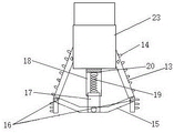
Further, the expansion stretching bracket comprises a first connecting rod and a supporting rod; the support rods are positioned in the vertical openings at the two sides of the first steel pipe; the connecting part of the first connecting rod and the supporting rod is rotationally connected through a pin shaft, a telescopic rod is fixed in the middle of the first connecting rod, a telescopic sleeve matched with the telescopic rod is sleeved above the telescopic rod, and a rubber gasket is fixed in the telescopic sleeve; a spiral spring is arranged in the telescopic sleeve, the upper end of the spiral spring is fixed with the rubber gasket, and the lower end of the spiral spring is connected with the upper end of the telescopic rod; the upper end of the supporting rod is hinged with the lower part of the side surface of the connecting block, and the center of the lower end of the connecting block is fixed with the upper end of the telescopic sleeve; the upper end of the connecting block is sleeved in the circular truncated cone; the connecting block is controlled to stretch out and draw back through hydraulic pressure, and the first connecting rod is of a telescopic structure.
Furthermore, open grooves are formed in the two sides of the bottom end of the first steel pipe and the two sides of the top end of the second steel pipe; an anti-skid gasket is arranged in the opening groove; the connecting fixture blocks of the connecting device are respectively clamped in the open grooves of the first steel pipe and the second steel pipe.
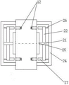
Furthermore, the connecting device comprises a connecting ring, the outer side of the connecting ring is fixedly arranged on the inner side of the connecting ring on the inner wall of the cylinder and is fixedly connected with a connecting pipe, and the connecting pipe is sleeved at the connecting seam of the first steel pipe and the second steel pipe; the second connecting rod penetrates through the sliding hole of the connecting ring, one side of the upper end and the lower end of the second connecting rod is fixedly connected with the inner wall of the cylinder through a spring, a connecting clamping block is fixed on the other side of the second connecting rod, and the size of the connecting clamping block is consistent with that of the opening groove.
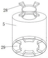
Furthermore, a convex cushion block is fixed right above the third steel pipe, arc blocks are arranged at the bottom of the third steel pipe, and the size of an opening between the arc blocks is consistent with that of the convex cushion block; the convex cushion blocks and the arc blocks are anisotropic magnets with magnetism.
Further, the bottom of the second steel pipe is provided with an arc-shaped block which is the same as the bottom of the third steel pipe.
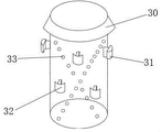
Furthermore, an annular scraper knife is fixed on the outer side of the top of the third steel pipe, the annular scraper knife is of a round table structure with a hollow interior, the small round table surface faces one side of the third steel pipe, the large round table surface faces one side of the third steel pipe, a first cutter head and a second cutter head are fixed on the periphery of the third steel pipe, the first cutter head and the second cutter head are arranged on the outer wall of the third steel pipe in a staggered mode, and the length of the second cutter head is smaller than that of the first cutter head; and grouting holes are spirally distributed on the outer wall of the third steel pipe.
Furthermore, the upper part of the drill bit is of a three-dimensional structure with a round bottom surface and an arc-shaped longitudinal section; the lower part of the drill bit is of a three-dimensional structure with round upper and lower surfaces and a right-angled trapezoid longitudinal section; the side surfaces of the upper part and the lower part are tangent.
Furthermore, drill bit teeth with different sizes are fixed on the upper portion of the drill bit, and fish scale sheets are fixed around the lower portion of the drill bit.
The pressure sensor is connected with an external display screen of the external equipment in a wireless or wired mode; still be provided with an angle of rectifying on the external equipment and set up the screen, the angle of rectifying is provided with an angle scale on setting up the screen, is provided with the angle knob at the sensor lateral part, and the angle knob passes through control circuit and is connected with the motor.
The invention has the beneficial effects that:
1. the device is mainly used for weak surrounding rocks and sandy surrounding rocks, so that a pointed cone type drill bit is avoided, a drill bit with a large contact area is adopted, drill bit teeth are adopted at the head of the drill bit, the soft rocks are more favorably drilled, and the fish scale grain pieces are arranged at the side parts of the drill bit, so that the purposes of easily breaking soil and drilling sand are achieved, the contact with the soft rocks is more favorably realized, and the soft rocks are more reliably and firmly bonded together.
2. Due to the unique design of the drill bit, the stress on each side surface of the drill bit is different, so that the function of correcting deviation is achieved.
3. The expansion stretching bracket has adjustable expansion angle, is suitable for steel floral tubes with different diameters and is convenient to replace.
4. The two steel pipes are fixed through the connecting device, and compared with the existing threaded connection, screw thread connection and welding, the connecting device is reasonable in stress and not easy to bend.
5. The pressure sensor is used for measuring the pressure borne by the device in real time, so that the correction is facilitated in time.
6. The drill bit and the steel pipe rotate separately, and the drill bit can correct the deviation and drill.
7. The second steel pipe and the third steel pipes are spliced by the convex cushion blocks and the arc-shaped blocks, so that the steel pipe support is convenient to disassemble and assemble, and the length of the whole support device can be adjusted according to actual conditions.
8. The third steel pipe is provided with an annular scraper which is attached in the circumferential direction and is in a round table-shaped structure, so that sandy soil, soft mudstone and silt can be scraped conveniently; the first blade and the second blade are arranged around the pipe shed, so that on one hand, drilling in soft rock is facilitated, and on the other hand, soil around the pipe shed can be removed; the periphery of the steel perforated pipe is provided with air holes to prevent soil and silt from entering the steel perforated pipe through the air holes or blocking the air holes to cause grouting failure, and the external high-pressure fan can prevent the air holes from being blocked and can also remove scum, soil and the like in the steel perforated pipe; and simultaneously, the air holes play the role of grouting holes.
Drawings
In order to more clearly illustrate the embodiments of the present invention or the technical solutions in the prior art, the drawings used in the description of the embodiments or the prior art will be briefly described below, it is obvious that the drawings in the following description are only some embodiments of the present invention, and for those skilled in the art, other drawings can be obtained according to the drawings without creative efforts.
Fig. 1 is a schematic structural view of a supporting device according to an embodiment of the present invention.
Fig. 2 is a schematic view of an expanded tension stent structure according to an embodiment of the present invention.
Fig. 3 is a schematic structural diagram of a connecting device according to an embodiment of the invention.
Fig. 4 is a schematic structural view of a convex cushion block and an arc block according to an embodiment of the invention.
FIG. 5 is a side view of a third steel pipe according to an embodiment of the present invention.
Fig. 6 is a schematic diagram of an external device according to an embodiment of the present invention.
In the figure, 1, a drill bit, 2, a first steel pipe, 3, a connecting device, 4, a second steel pipe, 5, a third steel pipe, 6, a fish scale sheet, 7, drill bit teeth, 8, a circular table, 9, a pressure sensor, 10, a rotating shaft, 11, a motor, 12, an anti-skid gasket, 13, a supporting rod, 14, a pointed drill bit, 15, a first connecting rod, 16, a pin shaft, 17, a telescopic rod, 18, a telescopic sleeve, 19, a spiral spring, 20, a rubber gasket, 21, a connecting ring, 22, a second connecting rod, 23, a connecting block, 24, a cylinder, 25, a connecting pipe, 26, a spring, 27, a connecting clamping block, 28, a convex cushion block, 29, an arc block, 30, an annular scraper, 31, a first tool bit, 32, a second tool bit, 33, a grouting hole, 34, a deviation-correcting angle setting screen, 35. and (4) expanding and stretching the stent, 36, externally connecting a display screen, 37 and rotating an angle knob.
Detailed Description
The technical solutions in the embodiments of the present invention will be clearly and completely described below with reference to the drawings in the embodiments of the present invention, and it is obvious that the described embodiments are only a part of the embodiments of the present invention, and not all of the embodiments. All other embodiments, which can be derived by a person skilled in the art from the embodiments given herein without making any creative effort, shall fall within the protection scope of the present invention.
As shown in fig. 1-6, the invention provides a deviation-correctable spliced pipe shed steel pipe supporting device used under a soft rock tunnel, which comprises a drill bit 1, a circular truncated cone 8, a first steel pipe 2, a connecting device 3, a second steel pipe 4 and a third steel pipe 5; wherein, the bottom of the drill bit 1 is sleeved with the round table 8; the circular truncated cone 8 is sleeved with an expansion stretching bracket 35 in the first steel pipe 2; the first steel pipe 2 and the second steel pipe 4 are detachably connected through a connecting device 3; the second steel pipe 4 is detachably connected with the third steel pipe 5.
Furthermore, the upper part of the drill bit 1 is of a three-dimensional structure with a round bottom surface and an arc-shaped longitudinal section; the lower part of the drill bit 1 is of a three-dimensional structure with round upper and lower surfaces and a right-angled trapezoid longitudinal section; the side surfaces of the upper part and the lower part are tangent; because the stressed areas on the left side and the right side are different, the stressed force is different, and the function of correcting deviation is achieved. For example, when the drilling direction is deviated to the left, the angle knob 37 at the side of the deviation correction angle setting screen 34 can be rotated to adjust, and when the angle is adjusted to 270 degrees, the adjustment is stopped, the drill bit 1 at this time can rotate, when the inclined part of the drill bit 1 rotates to the left, the rotation is stopped, and because the area of the inclined part at the left side is larger than the area of the flat part at the right side at this time, the thrust received at the left side is larger than the right side, so that the drill bit 1 can be gradually drilled to the right side, and the deviation correction effect is gradually realized.
In some embodiments, the upper portion of the drill bit 1 is provided with drill bit teeth 7 with different sizes, which not only increases the contact area with soft soil and is more favorable for drilling, but also is provided with scale blades 6 around the lower portion of the drill bit 1, i.e. the scale blades are like fish scale type blades, which are not only sharp and incomparable, and are easier to cut and drill in soft rock, but also are more favorable for relatively close fitting with soft rock, so that the drill bit 1 is prevented from slipping and deviating from the drilling direction.
In some embodiments, in order to realize the function of sensing deviation, a round table 8 with a hollow inner part is sleeved below the drill bit 1, and the drill bit 1 can freely rotate on the round table 8; a plurality of pressure sensors 9 are fixedly arranged on the periphery of the circular truncated cone 8; during the normal forward drilling process of the drill bit 1, the pressure of each pressure sensor 9 is basically kept unchanged, when the pressure value of the pressure sensor 9 in a certain direction is suddenly increased, the pressure of the drill bit 1 from the direction is increased at the moment, and the drill bit 1 is deviated in the opposite direction at the moment. When the worker finds that the values of the sensors of the pressure in a certain direction are all increased suddenly, the drilling is stopped, the inclined part of the drill bit 1 is adjusted to face the direction of the deviation of the drill bit 1, the drilling is started, and the function of correcting deviation is achieved.
In some embodiments, the pressure sensor 9 is connected to an external display 36 of the external device in a wireless or wired manner, and the external display 36 can display the offset angle of the drill bit 1.
In some embodiments, a rotating shaft 10 is fixedly connected to the center below the drill bit 1, the rotating shaft 10 is located in the circular truncated cone 8, the rotating shaft 10 is fixedly connected to an output end of a motor 11 inside the circular truncated cone 8, and the rotating shaft 10 is driven by the motor 11 to further drive the drill bit 1 to rotate.
Furthermore, vertical openings are formed in two sides of the first steel pipe 2, so that when the expansion and stretching support 35 is installed, the support rods 13 with the sharp drill bits 14 on two sides are stretched out of the vertical openings, soft rock drilling is performed by using the sharp drill bits 14 on two sides, the sharp drill bits 14 on two sides are arranged in a staggered mode, and therefore the situation that no dead angle exists in the drilling process and annular drilling is performed around the drill bits is guaranteed; as shown in fig. 2, the joint between the first connecting rod 15 of the expanding and stretching bracket 35 and the supporting rod 13 is rotatably connected by a pin 16, an expansion rod 17 is fixed in the middle of the first connecting rod 15, an expansion sleeve 18 matched with the expansion rod 17 is sleeved above the expansion rod 17, and a rubber gasket 20 is fixed in the expansion sleeve 18 to prevent slipping during expansion and to ensure firm connection; a spiral spring 19 is arranged in the telescopic sleeve 18, the upper end of the spiral spring 19 is fixed with a rubber gasket 20, and the lower end of the spiral spring is connected with the upper end of the telescopic rod 17; the upper end of the supporting rod 13 is hinged with the lower part of the side surface of the connecting block 23, and the center of the lower end of the connecting block 23 is fixed with the upper end of the telescopic sleeve 18; the upper end of the connecting block 23 is sleeved in the circular truncated cone 8, and the connecting block 23 and the circular truncated cone 8 can rotate freely. In the embodiment, the connecting block 23 is controlled to extend and retract through hydraulic pressure, and the first connecting rod 15 is of a telescopic structure; when the link block 23 is contracted, the coil spring 19 is extended to compress the first link rod 15 through the lower end of the support rod 13 hinged to the link block 23; when connecting block 23 extension, coil spring 19 compresses with telescopic sleeve 18, through the tensile first connecting rod 15 of the lower extreme with connecting block 23 articulated bracing piece 13 to this realizes the expansion of bracing piece 13, thereby play the purpose that bracing piece 13 slowly stretches out from vertical opening, when the flexible degree of connecting block 23 is different, the angle size of bracing piece 13 expansion is also different this moment, consequently can play the effect that all has the adaptability to the pipe shed of different sizes. When the steel pipes of different diameters need to be replaced, the expansion and stretching support 35 only needs to be stretched and then taken out from the original first steel pipe 2, then the new first steel pipe is installed, the connecting block 23 is controlled to stretch, the two support rods 13 of the expansion and stretching support 35 are clamped at the vertical opening of the first steel pipe 2, the expansion and stretching support 35 is prevented from falling off, and other parts are installed.
In some embodiments, open grooves are provided on both sides of the bottom end of the first steel pipe 2, and anti-slip pads 12 are provided inside the open grooves. The second steel pipe 4 is fixedly connected with the bottom end of the first steel pipe 2 through a connecting device 3, is also provided with an opening groove with the same size at a position with a certain length away from the top end, and is internally provided with an anti-skid gasket 12; the connecting fixture blocks 27 of the connecting device 3 are respectively clamped in the open grooves of the first steel pipe 2 and the second steel pipe 4, so as to play a role in fixing. In this embodiment, in order to facilitate the assembly and disassembly of the connecting device 3, the same sides of all the open grooves are set as inclined planes rather than vertical planes, and the connecting device 3 only needs to be rotated along the inclined plane direction to complete the disassembly during the disassembly, which is opposite to the disassembly rotation direction during the assembly.
In some embodiments, as shown in fig. 3, the connection device 3 includes a connection ring 21, an outer side of the connection ring 21 is fixedly installed on an inner wall of the cylinder 24, a connection pipe 25 is fixedly connected to an inner side of the connection ring 21, and the connection pipe 25 is sleeved at a connection seam of two steel pipes to tightly connect the steel pipes; the second connecting rod 22 passes through the sliding hole of the connecting ring 21, the second connecting rod 22 can move left and right in the sliding hole, one side of the upper end and the lower end of the second connecting rod 22 is fixedly connected with the inner wall of the cylinder 24 through a spring 26, the other side of the upper end and the lower end of the second connecting rod is fixedly provided with a connecting fixture block 27, and the size of the connecting fixture block 27 is basically consistent with that of the opening groove and is mainly used for being clamped into the opening groove; the spring 26 arranged between the second connecting rod 22 and the cylinder 24 is mainly used for controlling the extension and retraction of the connecting clamping block 27, when the connecting clamping block 27 is not clamped into the open groove, the spring 26 is compressed, the connecting device 3 is moved, when the connecting clamping block 27 is clamped into the open groove, the spring 26 is restored to a normal position, when the spring 26 is compressed, the connecting clamping block 27 can be clamped into the open groove, and when the spring 26 rebounds, the connecting clamping block 27 is ejected. The connection setting of this embodiment not only lets the connection of steel pipe more firm reliable, changes moreover and dismantles the installation steel pipe, and is reasonable and difficult emergence bending than current threaded connection, screw thread connection, welding atress are just connected relatively.
Further, as shown in fig. 4, a convex cushion block 28 with four blades is fixed right above the third steel pipe 5, an arc block 29 is provided at the bottom of the third steel pipe 5, and the size of the opening between the arc blocks 29 is the same as that of the convex cushion block 28. When needs splice a plurality of third steel pipes 5 so that the pipe shed extension, insert protruding type cushion 28 in the third steel pipe 5 above along the opening between the arc piece 29, then rotatory protruding type cushion 28 and the inseparable laminating of arc piece 29 of messenger: since the convex block 28 and the arc block 29 are opposite magnets with strong magnetism (in some embodiments, they can also be electromagnetic structures), they are tightly connected when they are close to each other. Similarly, when the next section of steel pipe is spliced, the shed is gradually spliced to a proper size in the same operation, and the length of each section of shed steel pipe is not too long.
In some embodiments, for convenience of installation, the bottom of the second steel pipe 4 is also provided with an arc-shaped block 29 which is the same as the bottom of the third steel pipe 5, so that the third steel pipe 5 can be conveniently spliced with the second steel pipe 4.
In some embodiments, as shown in fig. 5, an annular scraper 30 is fixed on the top outer side of the third steel pipe 5, and the annular scraper 30 is a truncated cone-shaped structure with a hollow interior, wherein the small circular table surface faces the side where the drill bit 1 is located, and the large circular table surface faces the side where the third steel pipe 5 is located, so as to facilitate scraping of sandy soil, weak mudstone and sludge; a first cutter head 31 and a second cutter head 32 are fixed around the third steel pipe 5, and each cutter head and the third steel pipe 5 are of an integrally formed structure, so that the integral structural strength of the third steel pipe is improved; the first cutter heads 31 and the second cutter heads 32 are arranged on the outer wall of the third steel pipe 5 in a staggered mode, and the length of the second cutter heads 32 is smaller than that of the first cutter heads 31. The first cutter head 31 and the second cutter head 32 can break up the adhesive lumps and rocks encountered in the soft rock tunnel, and are more favorable for drilling the third steel pipe 5. Wind holes and grouting holes 33 are spirally distributed in the outer wall of the third steel pipe 5, and are connected with an external high-pressure fan, so that wind can penetrate through the inside of the third steel pipe 5, sandy soil and scum are discharged from the wind holes, and scattered hole broken stones are removed; when grouting is needed, the grouting function is achieved.
In some embodiments, as shown in fig. 6, a deviation correction angle setting screen 34 is further disposed on the external device, an angle scale is disposed on the deviation correction angle setting screen 34, an angle knob 37 is disposed on the side of the sensor, and the angle to be corrected can be adjusted by the angle knob 37 (i.e., the motor 11 is controlled by the control circuit to adjust the position of the inclined plane of the drill bit 1). In the angle scale, the large scale is degree, the small scale is degree, the 60 degree is 1 degree, for example, when the angle needing to be corrected is 36 degrees 42 ', the angle can be adjusted to 36 degrees through the rotation angle knob 37, and the angle can be adjusted to 42' by slightly pressing the angle knob 37 to the lower part, so that more accurate correction of the drilling angle can be realized.
It should be noted that all circuit connections in the present invention are conventional in the art.
The working process of the invention is as follows:
when drilling is needed, the third steel pipe 5 of the support device is connected with an external power device, and the power device is utilized to drive the third steel pipe 5 to rotate so as to drive the second steel pipe 4 and the first steel pipe 2 to rotate; meanwhile, a motor 11 in the drill bit 1 is turned on to drive the drill bit 1 to rotate, and the rotation direction of the drill bit 1 is required to be consistent with the rotation direction of each steel pipe; the whole supporting device is pushed to drill forwards by the application of an external pushing device. The rotary table 8 is kept not to rotate in the drilling process, when the numerical value of the pressure sensor 9 on one side of the pressure sensors 9 on the periphery of the rotary table 8 is increased, the drilling direction is indicated to be deviated, the external display screen 36 displays the drilling deviation angle, at the moment, the external power device and the motor 11 of the drill bit 1 are turned off, and the forward drilling is stopped. The position of the inclined plane of the drill bit 1 is adjusted through an angle knob 37 on the deviation-correcting angle setting screen 34, after the position is adjusted, only a power device is started to drive each steel pipe to rotate, but the drill bit 1 is not moved, and at the moment, the whole supporting device drills in the correct direction to realize deviation correction. After the deviation is corrected to the right position, the motor 11 of the drill bit 1 is started to rotate the drill bit 1, and normal drilling is started.
When drilling, the wind energy penetrates through the third steel pipe 5 by connecting an external high-pressure fan with the third steel pipe 5, so that sand and scum are discharged from wind holes, and scattered hole broken stones are removed; when grouting is needed, the fan is turned off, and the slurry is injected into the tunnel from the grouting hole 33. And after the slurry is filled, the power device and the motor 11 are closed, and the drilling is stopped.
All the embodiments in the present specification are described in a related manner, and the same and similar parts among the embodiments may be referred to each other, and each embodiment focuses on the differences from the other embodiments.
The above description is only for the preferred embodiment of the present invention, and is not intended to limit the scope of the present invention. Any modification, equivalent replacement, or improvement made within the spirit and principle of the present invention shall fall within the protection scope of the present invention.
Claims (10)
1. A deviation-rectifying type spliced pipe shed steel pipe supporting device used under a soft rock tunnel is characterized by comprising a drill bit (1), a circular truncated cone (8), a first steel pipe (2), a second steel pipe (4) and a third steel pipe (5); the bottom of the drill bit (1) is sleeved with the round table (8); the round table (8) is sleeved with an expansion stretching bracket (35) in the first steel pipe (2); the first steel pipe (2) and the second steel pipe (4) are detachably connected through a connecting device (3); the second steel pipe (4) is detachably connected with the third steel pipe (5); a rotating shaft (10) is fixedly connected to the center of the lower portion of the drill bit (1), the rotating shaft (10) is located in the circular truncated cone (8), and the rotating shaft (10) is fixedly connected with the output end of a motor (11) in the circular truncated cone (8); and pressure sensors (9) are fixedly arranged on the periphery of the circular truncated cone (8).
2. The deviation-rectifying type spliced pipe shed steel pipe supporting device used under the soft rock tunnel according to the claim 1, characterized in that the expanding and stretching bracket (35) comprises a first connecting rod (15) and a supporting rod (13); the support rods (13) are positioned in vertical openings at two sides of the first steel pipe (2); the connecting part of the first connecting rod (15) and the supporting rod (13) is rotatably connected through a pin shaft (16), a telescopic rod (17) is fixed in the middle of the first connecting rod (15), a telescopic sleeve (18) matched with the telescopic rod (17) is sleeved above the telescopic rod (17), and a rubber gasket (20) is fixed inside the telescopic sleeve (18); a spiral spring (19) is arranged in the telescopic sleeve (18), the upper end of the spiral spring (19) is fixed with the rubber gasket (20), and the lower end of the spiral spring is connected with the upper end of the telescopic rod (17); the upper end of the supporting rod (13) is hinged with the lower part of the side surface of the connecting block (23), and the center of the lower end of the connecting block (23) is fixed with the upper end of the telescopic sleeve (18); the upper end of the connecting block (23) is sleeved in the round table (8); the connecting block (23) is controlled to stretch out and draw back through hydraulic pressure, and the first connecting rod (15) is of a telescopic structure.
3. The deviation-rectifying spliced pipe shed steel pipe supporting device used under the soft rock tunnel according to claim 1, wherein open grooves are formed in two sides of the bottom end of the first steel pipe (2) and two sides of the top end of the second steel pipe (4); an anti-skid gasket (12) is arranged in the opening groove; the connecting clamping blocks (27) of the connecting device (3) are respectively clamped in the opening grooves of the first steel pipe (2) and the second steel pipe (4).
4. The deviation-rectifying spliced pipe shed steel pipe supporting device used under the soft rock tunnel according to claim 1 or 3, wherein the connecting device (3) comprises a connecting ring (21), the outer side of the connecting ring (21) is fixedly arranged on the inner side of the connecting ring (21) on the inner wall of the cylinder (24) to be fixedly connected with a connecting pipe (25), and the connecting pipe (25) is sleeved at the connecting seam of the first steel pipe (2) and the second steel pipe (4); the second connecting rod (22) penetrates through the sliding hole of the connecting ring (21), one side of the upper end and the lower end of the second connecting rod (22) is fixedly connected with the inner wall of the cylinder (24) through a spring (26), a connecting clamping block (27) is fixed on the other side of the second connecting rod (22), and the size of the connecting clamping block (27) is consistent with that of the opening groove.
5. The deviation-rectifying spliced pipe shed steel pipe supporting device used under the soft rock tunnel according to claim 1, wherein a convex cushion block (28) is fixed right above the third steel pipe (5), an arc-shaped block (29) is arranged at the bottom of the third steel pipe (5), and the size of an opening between the arc-shaped blocks (29) is consistent with that of the convex cushion block (28); the convex cushion block (28) and the arc block (29) are anisotropic magnets with magnetism.
6. The deviation-rectifying spliced pipe shed steel pipe supporting device used under the soft rock tunnel according to claim 1 or 5, characterized in that the bottom of the second steel pipe (4) is provided with an arc-shaped block (29) which is the same as the bottom of the third steel pipe (5).
7. The spliced pipe shed steel pipe supporting device capable of correcting the deviation under the soft rock tunnel according to claim 1, wherein an annular earth scraper (30) is fixed on the outer side of the top of the third steel pipe (5), the annular earth scraper (30) is of a round table structure with a hollow interior, a small round table surface faces to one side where the drill bit (1) is located, a large round table surface faces to one side where the third steel pipe (5) is located, a first cutter head (31) and a second cutter head (32) are fixed on the periphery of the third steel pipe (5), the first cutter head (31) and the second cutter head (32) are arranged on the outer wall of the third steel pipe (5) in a staggered mode, and the length of the second cutter head (32) is smaller than that of the first cutter head (31); and grouting holes (33) are spirally distributed on the outer wall of the third steel pipe (5).
8. The deviation-rectifying spliced pipe shed steel pipe supporting device used under the soft rock tunnel according to claim 1, wherein the upper part of the drill bit (1) is of a three-dimensional structure with a round bottom surface and an arc-shaped longitudinal section; the lower part of the drill bit (1) is of a three-dimensional structure with round upper and lower surfaces and right trapezoid longitudinal section; the side surfaces of the upper part and the lower part are tangent.
9. The deviation-rectifying spliced pipe shed steel pipe supporting device used under the soft rock tunnel according to claim 1 or 8, characterized in that drill bit teeth (7) with different sizes are fixed on the upper part of the drill bit (1), and fish scale sheets (6) are fixed around the lower part of the drill bit (1).
10. The spliced pipe shed steel pipe supporting device capable of correcting the deviation under the soft rock tunnel according to claim 1, characterized by further comprising external equipment, wherein the pressure sensor (9) is connected with an external display screen (36) of the external equipment in a wireless or wired mode; the external equipment is also provided with a deviation-correcting angle setting screen (34), an angle scale is arranged on the deviation-correcting angle setting screen (34), an angle knob (37) is arranged on the side part of the sensor, and the angle knob (37) is connected with the motor (11) through a control circuit.
Priority Applications (1)
| Application Number | Priority Date | Filing Date | Title |
|---|---|---|---|
| CN202210823574.3A CN115045617A (en) | 2022-07-14 | 2022-07-14 | Deviation-rectifying type spliced pipe shed steel pipe supporting device used under soft rock tunnel |
Applications Claiming Priority (1)
| Application Number | Priority Date | Filing Date | Title |
|---|---|---|---|
| CN202210823574.3A CN115045617A (en) | 2022-07-14 | 2022-07-14 | Deviation-rectifying type spliced pipe shed steel pipe supporting device used under soft rock tunnel |
Publications (1)
| Publication Number | Publication Date |
|---|---|
| CN115045617A true CN115045617A (en) | 2022-09-13 |
Family
ID=83164940
Family Applications (1)
| Application Number | Title | Priority Date | Filing Date |
|---|---|---|---|
| CN202210823574.3A Pending CN115045617A (en) | 2022-07-14 | 2022-07-14 | Deviation-rectifying type spliced pipe shed steel pipe supporting device used under soft rock tunnel |
Country Status (1)
| Country | Link |
|---|---|
| CN (1) | CN115045617A (en) |
Cited By (1)
| Publication number | Priority date | Publication date | Assignee | Title |
|---|---|---|---|---|
| CN116876985A (en) * | 2023-06-09 | 2023-10-13 | 金中天水利建设有限公司 | EJO drill bit easy to correct |
-
2022
- 2022-07-14 CN CN202210823574.3A patent/CN115045617A/en active Pending
Cited By (2)
| Publication number | Priority date | Publication date | Assignee | Title |
|---|---|---|---|---|
| CN116876985A (en) * | 2023-06-09 | 2023-10-13 | 金中天水利建设有限公司 | EJO drill bit easy to correct |
| CN116876985B (en) * | 2023-06-09 | 2023-12-26 | 金中天水利建设有限公司 | Easy-to-correct drill bit |
Similar Documents
| Publication | Publication Date | Title |
|---|---|---|
| KR101467142B1 (en) | Pressure grouting enabled steel pipe pile and penetration device of the same and pile construction method using the same | |
| CN109853524B (en) | Construction method of expanded head stiff cement soil composite special-shaped pile | |
| CN109736715B (en) | Variable-section spiral drilling tool and construction method of variable-section bored pile | |
| CN115045617A (en) | Deviation-rectifying type spliced pipe shed steel pipe supporting device used under soft rock tunnel | |
| CN110700760B (en) | Multi-supporting-disc anchoring system hole expanding equipment and construction method | |
| CN106812470B (en) | A kind of borehole-enlarging drilling tool | |
| CN203175403U (en) | Dry drilling pore-forming under-reaming drill bit of rotary drilling rig | |
| RU2485249C2 (en) | Equipment for jet cementation | |
| EP1719841A1 (en) | Method and equipment for constructing micropiles in soil | |
| CN210090077U (en) | Portable ground detects sampling device | |
| CN114412555A (en) | Goaf grouting wall protecting pipe recycling device and construction method | |
| KR20060082593A (en) | Tension and compressure supporting pile | |
| CN108360514B (en) | Rotary extrusion double-layer nested dish-shaped enlarged footing anchor rod and use method thereof | |
| CN217841523U (en) | Miniature steel-pipe pile construction drilling equipment and construction system | |
| CN111894004A (en) | Foundation pit diagonal bracing device and construction method | |
| CN214008274U (en) | Pipe jacking device for pipeline repair | |
| JPH11350473A (en) | Execution method for steel pipe pile | |
| CN110952535B (en) | Steel pipe pile construction method | |
| CN210460508U (en) | Adjustable anchor rope hole bottom expanding drill bit | |
| CN111893999B (en) | Pile pulling guide frame and pile pulling method for waste inclined piles | |
| CN203685036U (en) | Transverse widener | |
| CN210530749U (en) | Self-advancing pipe shed drilling tool for tunnel soft rock excavation | |
| CN211623339U (en) | Advanced small catheter support | |
| CN220849576U (en) | Mechanical multi-diameter reaming and stirring drill bit device for construction of foundation pit supporting inclined strut pile | |
| CN206503613U (en) | It is a kind of to bore hollow slip casting expansion anchor rod certainly |
Legal Events
| Date | Code | Title | Description |
|---|---|---|---|
| PB01 | Publication | ||
| PB01 | Publication | ||
| SE01 | Entry into force of request for substantive examination | ||
| SE01 | Entry into force of request for substantive examination |