CN115041311B - Environment-friendly electrostatic combined bag-type dust collector - Google Patents
Environment-friendly electrostatic combined bag-type dust collector Download PDFInfo
- Publication number
- CN115041311B CN115041311B CN202210953117.6A CN202210953117A CN115041311B CN 115041311 B CN115041311 B CN 115041311B CN 202210953117 A CN202210953117 A CN 202210953117A CN 115041311 B CN115041311 B CN 115041311B
- Authority
- CN
- China
- Prior art keywords
- ring
- dust removal
- dust
- dust collector
- pipe
- Prior art date
- Legal status (The legal status is an assumption and is not a legal conclusion. Google has not performed a legal analysis and makes no representation as to the accuracy of the status listed.)
- Active
Links
Images
Classifications
-
- B—PERFORMING OPERATIONS; TRANSPORTING
- B04—CENTRIFUGAL APPARATUS OR MACHINES FOR CARRYING-OUT PHYSICAL OR CHEMICAL PROCESSES
- B04C—APPARATUS USING FREE VORTEX FLOW, e.g. CYCLONES
- B04C9/00—Combinations with other devices, e.g. fans, expansion chambers, diffusors, water locks
-
- B—PERFORMING OPERATIONS; TRANSPORTING
- B03—SEPARATION OF SOLID MATERIALS USING LIQUIDS OR USING PNEUMATIC TABLES OR JIGS; MAGNETIC OR ELECTROSTATIC SEPARATION OF SOLID MATERIALS FROM SOLID MATERIALS OR FLUIDS; SEPARATION BY HIGH-VOLTAGE ELECTRIC FIELDS
- B03C—MAGNETIC OR ELECTROSTATIC SEPARATION OF SOLID MATERIALS FROM SOLID MATERIALS OR FLUIDS; SEPARATION BY HIGH-VOLTAGE ELECTRIC FIELDS
- B03C3/00—Separating dispersed particles from gases or vapour, e.g. air, by electrostatic effect
- B03C3/017—Combinations of electrostatic separation with other processes, not otherwise provided for
-
- B—PERFORMING OPERATIONS; TRANSPORTING
- B04—CENTRIFUGAL APPARATUS OR MACHINES FOR CARRYING-OUT PHYSICAL OR CHEMICAL PROCESSES
- B04C—APPARATUS USING FREE VORTEX FLOW, e.g. CYCLONES
- B04C9/00—Combinations with other devices, e.g. fans, expansion chambers, diffusors, water locks
- B04C2009/001—Combinations with other devices, e.g. fans, expansion chambers, diffusors, water locks with means for electrostatic separation
-
- B—PERFORMING OPERATIONS; TRANSPORTING
- B04—CENTRIFUGAL APPARATUS OR MACHINES FOR CARRYING-OUT PHYSICAL OR CHEMICAL PROCESSES
- B04C—APPARATUS USING FREE VORTEX FLOW, e.g. CYCLONES
- B04C9/00—Combinations with other devices, e.g. fans, expansion chambers, diffusors, water locks
- B04C2009/004—Combinations with other devices, e.g. fans, expansion chambers, diffusors, water locks with internal filters, in the cyclone chamber or in the vortex finder
-
- Y—GENERAL TAGGING OF NEW TECHNOLOGICAL DEVELOPMENTS; GENERAL TAGGING OF CROSS-SECTIONAL TECHNOLOGIES SPANNING OVER SEVERAL SECTIONS OF THE IPC; TECHNICAL SUBJECTS COVERED BY FORMER USPC CROSS-REFERENCE ART COLLECTIONS [XRACs] AND DIGESTS
- Y02—TECHNOLOGIES OR APPLICATIONS FOR MITIGATION OR ADAPTATION AGAINST CLIMATE CHANGE
- Y02A—TECHNOLOGIES FOR ADAPTATION TO CLIMATE CHANGE
- Y02A50/00—TECHNOLOGIES FOR ADAPTATION TO CLIMATE CHANGE in human health protection, e.g. against extreme weather
- Y02A50/20—Air quality improvement or preservation, e.g. vehicle emission control or emission reduction by using catalytic converters
- Y02A50/2351—Atmospheric particulate matter [PM], e.g. carbon smoke microparticles, smog, aerosol particles, dust
Abstract
The invention discloses an environment-friendly electrostatic combined type bag-type dust collector, wherein a dust collection pipe is provided with a combined dust collection assembly, the top end of an inner exhaust pipe is symmetrically hinged with a movable baffle, the edge of a magnetic suction ring is connected with a sealing ring through uniformly distributed strings, the top surface of a bottom ring is symmetrically welded with a spring plate, the top surface of a hexagonal plate is provided with a vibration motor, the outer side of the dust collection pipe is provided with a replacement adjusting assembly, and the bottom end of a cyclone dust collector is connected with an exhaust cleaning assembly.
Description
Technical Field
The invention relates to the technical field of dust removal, in particular to an environment-friendly electrostatic combined type bag-type dust remover.
Background
Dust removal is a technology for removing particulate matters from dust-containing gas, and the dust-containing industrial waste gas or the dust-containing industrial waste gas is generated in mechanical processes such as crushing, screening, conveying and blasting of solid matters or in processes such as combustion, high-temperature melting and chemical reaction, and can be divided into a mechanical dust remover, an electric dust remover, a filtering dust remover, a washing dust remover and the like according to a trapping mechanism, and the dust remover is commonly an electrostatic dust remover, a cyclone dust remover, a bag-type dust remover, an inertial dust remover and the like.
The bag-type dust collector disclosed in the Chinese patent No. 201821129960.8 has the characteristics of simplicity and convenience in use, but the dust collector in the current market is used for removing dust, different dust collectors can be combined for use in order to improve the dust removing effect, for example, a cyclone dust collector and the bag-type dust collector are connected in series, the cyclone dust collector is used for cooling and removing large particles, and then the bag-type dust collector is used for filtering, but the combined dust removing equipment occupies a large space when used, the cleaning difficulty is increased accordingly, and the use is not convenient enough.
Disclosure of Invention
The invention provides an environment-friendly electrostatic combined bag-type dust collector, which can effectively solve the problems that the dust collecting equipment provided by the background technology occupies large space when being combined for use, the cleaning difficulty is increased along with the large space, and the use is not convenient enough.
In order to achieve the above object, the present invention provides the following technical solutions, including:
when the blast fan is blowing, the movable baffle is horizontal, the magnetic suction ring box and the sealing ring are separated, and air sequentially enters the filter bag, the dust removal pipe and the cyclone dust collector to be cleaned;
replacing the adjusting assembly, lifting the dust removal pipe by the lifting electric push rod to separate from the bottom ring, separating the sliding plate from the supporting plate, rotating the motor to drive the top mounting ring to rotate 180 degrees, retracting the hydraulic rod to drive the dust removal pipe to move downwards, rotating the lead screw to separate from the rotating block, and rotating the rotating block along the rotating shaft until the dust removal pipe rotates 90 degrees;
the clean subassembly of discharge, clean motor rotate, drive interior spiral area and clean section of thick bamboo and rotate, and the adnexed dust of inner wall is scraped to interior spiral area, and the dust falls in the clean inslot of clean section of thick bamboo top, and the dust falls along with the rotation of clean section of thick bamboo.
Preferably, the dust removal pipe is provided with a combined dust removal assembly, and the combined dust removal assembly comprises a bottom ring, a butt joint electric push rod, a cyclone dust collector, an inner exhaust pipe, a movable baffle plate, a conical cover, a magnetic suction ring, a conical hole, a dust removal hole, a string, a sealing ring, a mounting plate, a guide fan blade, a bottom ring, a spring plate, a top ring, a filter bag, a hexagonal plate, a vibration motor, an inner threaded pipe, an insulation frame, an electrode rod, a dust collection plate, an end cover, an outer exhaust pipe and a blast fan;
the bottom end of the dust removal pipe is movably sleeved with a bottom ring, the bottom ring and the bottom end of the dust removal pipe are welded with butt joint rings, butt joint electric push rods are installed at the positions, above the butt joint rings, of the dust removal pipe, and the bottom ring is welded to the top end of the cyclone dust collector;
the cyclone dust collector comprises a cyclone dust collector and is characterized in that an inner air exhaust pipe is welded at the top end of the cyclone dust collector, movable baffles are symmetrically hinged at the top end of the inner air exhaust pipe, a conical cover is sleeved on the outer side of the inner air exhaust pipe and fixedly embedded at the bottom end of the dust removal pipe, conical holes are uniformly formed in the bottom end of the conical cover, a magnetic suction ring is bonded at the position, close to the bottom end of the conical cover, of the top end inside the cyclone dust collector, dust removal holes are formed in the magnetic suction ring and the top end of the cyclone dust collector corresponding to the conical holes, and the edge of the magnetic suction ring is connected with a sealing ring through uniformly distributed thin ropes;
the utility model discloses a set up the dust removal pipe, including the dust removal pipe, the mounting panel top surface is installed the guide flabellum, the mounting panel top surface evenly runs through to inlay has the bottom ring, bottom ring top surface symmetrical welding has the spring board, the welding of spring board top has the apical ring, the filter bag is crossed to the joint between apical ring and the bottom ring, and is a plurality of the apical ring all is through screw connection in hexagonal plate bottom surface, vibrating motor is installed to the hexagonal plate top surface, the welding of filter bag top surface department is crossed to the hexagonal plate has the internal thread pipe, there is the insulation frame internal thread intraduct through threaded connection, the insulation frame middle part runs through and installs the electrode bar, the insulation frame both ends have all welded the dust-collecting plate, the dust removal pipe joint has the end cover, end cover top middle part runs through and installs outer trachea of arranging, outer trachea one end is inlayed and is had the blast fan.
Preferably, the diameter of the extending end of the butting electric push rod is equal to the diameter of an inner hole of the butting ring, the longitudinal section of the tapered hole is in a trapezoid shape with a long upper part and a short lower part, and the diameter of the bottom end of the tapered hole is equal to the diameter of the dust removal hole.
Preferably, the inner wall of the top end of the inner exhaust pipe close to the movable baffle is a smooth inclined plane, and the top end of the conical cover is flush with the top end of the inner exhaust pipe.
Preferably, the butt joint electric push rod, the vibration motor and the blowing fan input end are respectively and electrically connected with the external power supply output end, the electrode rod is connected with the negative electrode of the external power supply, and the dust collecting plate is connected with the positive electrode of the external power supply.
Preferably, a replacement adjusting assembly is arranged on the outer side of the dust removing pipe and comprises a top mounting ring, a rotating motor, a lifting electric push rod, a rotating block, a rotating shaft, a lead screw, a hydraulic rod, a reinforcing ring, a grounding plate, a limiting ring, a collecting box, a sliding plate, a clamping strip, a supporting plate, a clamping groove, a fixing pipe, a rotating seat and a bottom mounting ring;
a top mounting ring is fixedly clamped on the outer side of the dust removing pipe, a rotating motor is mounted on one side of the top end of the top mounting ring, an output shaft of the rotating motor penetrates through the top mounting ring to be connected with an extending end of a lifting electric push rod, the bottom end of the lifting electric push rod is connected with a rotating block through a screw, a bottom mounting ring is sleeved on the outer side of the cyclone dust remover, the rotating block is connected with one end of the bottom mounting ring through a rotating shaft, two ends of the rotating shaft penetrate through two sides of a rotating base in a rotating mode, one end of the rotating shaft is connected with a lead screw in a welding mode, the bottom surface of the bottom mounting ring is uniformly connected with an extending end of a hydraulic rod, the four hydraulic rods are all connected with a strengthening ring, the bottom ends of the hydraulic rods are all connected with a ground plate, a limiting ring is welded in the middle of the top surface of the ground plate, and a collecting box is slidably mounted at the position, at the bottom end of the cyclone dust remover, inside the limiting ring;
the outer trachea of arranging one end welding has the sliding plate, the symmetrical welding in sliding plate side has the card strip, sliding plate one side activity joint has the layer board, the layer board corresponds card strip department and has seted up the draw-in groove, the layer board middle part through connection has fixed pipe.
Preferably, the output ends of the rotating motor and the lifting electric push rod are electrically connected with the output end of an external power supply respectively, the rotating shaft penetrates through the screw holes of the rotating block and the rotating seat, the screw holes are matched with the screw rod, the side face of the supporting plate is L-shaped, and the clamping strips are matched with the clamping grooves.
Preferably, the bottom end of the cyclone dust collector is connected with a discharge cleaning assembly, and the discharge cleaning assembly comprises an inner spiral belt, a supporting scraping rod, a rotating cross rod, a transmission rod, a partition plate, a driving bevel gear, a driven gear, a cleaning motor, a shielding cover, a rotating frame, a cleaning cylinder, a cleaning groove, a driven rod, a driven bevel gear, an ash storage cover, a barrier strip and a driving gear;
the dust collection device is characterized in that an inner spiral belt is movably placed inside the cyclone dust collector, a supporting scraping rod is welded at the position, close to the inner wall of the cyclone dust collector, of the inner spiral belt, the bottom end of the inner spiral belt is connected with a rotating transverse rod in a welded mode, a transmission rod is connected to the middle of the bottom end of the rotating transverse rod through threads, a partition plate is movably sleeved at the middle of the transmission rod, a driving bevel gear is sleeved at the position, below the partition plate, of the transmission rod, a driven gear is sleeved at the bottom end of the transmission rod, a driving gear is meshed with one side of the driven gear and connected with an output shaft of a cleaning motor, the driven gear, the driving gear and the cleaning motor are all located inside a shielding cover, the transmission rod movably penetrates through the top end of the shielding cover, a rotating frame is symmetrically welded to the top surface of the shielding cover, a cleaning barrel is connected to the top end of the rotating frame through a rotating shaft, cleaning grooves are evenly formed in the outer side of the cleaning barrel, a driven rod is welded at the middle inside the driven rod, one end of the driven bevel gear is sleeved with a driven bevel gear, a dust storage cover is sleeved at the bottom end of the cyclone dust collection device, and a baffle strip is symmetrically welded to the bottom end of the cleaning barrel.
Preferably, the input end of the cleaning motor is electrically connected with the output end of the external power supply, the inner spiral belt is attached to the inner wall of the cyclone dust collector at the outer side, the cleaning motor is clamped and installed inside the shielding cover, and the top surface of the shielding cover is an upward convex smooth curved surface.
Preferably, deposit the clean section of thick bamboo curved surface of laminating of ash cover bottom indent, the baffle is the semicircle board, and the baffle diameter equals clean section of thick bamboo external diameter.
Compared with the prior art, the invention has the beneficial effects that:
1. be provided with combination dust removal subassembly, install the sack cleaner in the cyclone top, electric dust collecting equipment installs in the sack of sack cleaner, when the blast fan stops, dust removal pipe joint is in the butt joint intra-annular, adjustable fender is vertical, magnetism inhales the ring and adsorbs the sealing ring, the dirty flue gas gets into cyclone in proper order, dust removal pipe and filter bag dust removal, occupation space significantly reduces when guaranteeing dust removal effect separately, when the blast fan is ventilated, the adjustable fender level, magnetism inhales ring box sealing ring separation, the air gets into in proper order and crosses the filter bag, dust removal pipe and cyclone blowback clearance, vibrating motor drives the vibration of hexagon plate, the dust falls down from crossing the filter bag, slide along the taper cover again, see through the bottom that the dust removal hole falls into cyclone, vibration and blowback cooperation, the clearance is simple more convenient.
2. Be provided with replacement adjusting part, lifting electric push rod lifting dust removal pipe breaks away from the foundation ring, sliding plate and layer board separation, it drives a collar and rotates 180 to rotate the motor, the hydraulic stem shrink drives the dust removal pipe and moves down, it breaks away from the turning block to rotate the lead screw, the turning block rotates along the pivot, until dust removal pipe rotates 90, when separation dust removal pipe and cyclone convenient and fast, the high while change angle of dust removal pipe has been reduced, reduce the degree of difficulty of overhauing and clearing up, cooperation combination dust removal subassembly and the clean subassembly of discharging, there is better dust removal effect.
3. Be provided with the clean subassembly of discharge, clean motor rotates, spiral area and clean section of thick bamboo rotate in the drive, interior spiral area strikes off the adnexed dust of inner wall, the dust falls into the clean inslot of clean section of thick bamboo top, the dust falls down along with the rotation of clean section of thick bamboo, clean section of thick bamboo cooperation accumulational dust seals the cyclone bottom, guarantee the air output of exhaust pipe in the cyclone, and adnexed dust of cyclone inner wall can be cleared up to pivoted interior spiral area, the deashing structure of cooperation combination dust removal subassembly uses, the dust that falls down then falls into in the collecting box of replacement adjusting part bottom, promote along the spacing collar again, the replacement collecting box, collect simple facility.
To sum up, the combination dust removal subassembly is with cyclone, bag collector and electrostatic precipitator make up, occupation space significantly reduces when guaranteeing dust removal effect separately, the degree of difficulty of maintenance and clearance is reduced to the replacement adjusting part, cooperation combination dust removal subassembly and the clean subassembly of discharge, there is better dust removal effect, when the air output of the interior exhaust pipe of cyclone is guaranteed to the clean subassembly of discharge, also cooperate combination dust removal subassembly and replacement adjusting part to use, further strengthen the effect of removing dust and deashing.
Drawings
The accompanying drawings, which are included to provide a further understanding of the invention and are incorporated in and constitute a part of this specification, illustrate embodiments of the invention and together with the description serve to explain the principles of the invention and not to limit the invention.
In the drawings:
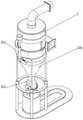
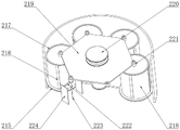
FIG. 1 is a schematic structural view of the present invention;
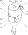
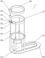
FIG. 2 is a schematic structural view of the modular dusting assembly of the present invention;
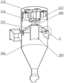
FIG. 3 is a schematic view of the installation structure of the internal exhaust duct of the present invention;
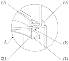
FIG. 4 is a schematic view of the structure of area A of FIG. 3 according to the present invention;
FIG. 5 is a schematic view of the mounting structure of the hexagonal plate of the present invention;
FIG. 6 is a schematic view of the mounting structure of the top mounting ring of the present invention;
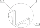
FIG. 7 is a schematic view of the structure of the area B of FIG. 2 according to the present invention;
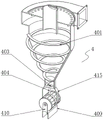
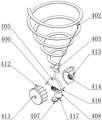
FIG. 8 is a schematic view of the construction of the exhaust cleaning assembly of the present invention;
FIG. 9 is a schematic view of the installation structure of the dust boot of the present invention;
reference numbers in the figures: 1. a dust removal pipe;
2. a combined dust removal assembly; 201. a bottom ring; 202. a docking ring; 203. butting the electric push rod; 204. a cyclone dust collector; 205. an inner exhaust duct; 206. a movable baffle; 207. a conical cover; 208. a magnetic ring; 209. a tapered hole; 210. a dust removal hole; 211. a string; 212. a seal ring; 213. mounting a plate; 214. guiding the fan blades; 215. a bottom ring; 216. a spring plate; 217. a top ring; 218. a filter bag; 219. a hexagonal plate; 220. a vibration motor; 221. an internally threaded tube; 222. an insulating frame; 223. an electrode rod; 224. a dust collecting plate; 225. an end cap; 226. discharging the air out of the air outlet pipe; 227. a blower fan;
3. replacing the adjustment assembly; 301. a top mounting ring; 302. rotating the motor; 303. lifting the electric push rod; 304. rotating the block; 305. a rotating shaft; 306. a screw rod; 307. a hydraulic lever; 308. a reinforcing ring; 309. a ground plate; 310. a limiting ring; 311. a collection box; 312. a sliding plate; 313. clamping the strip; 314. a support plate; 315. a card slot; 316. a fixed tube; 317. a rotating seat; 318. a bottom mounting ring;
4. a discharge cleaning assembly; 401. an inner helical band; 402. supporting the scraping rod; 403. rotating the cross bar; 404. a transmission rod; 405. a partition plate; 406. a drive bevel gear; 407. a driven gear; 408. cleaning the motor; 409. a shield cover; 410. a rotating frame; 411. a cleaning cartridge; 412. cleaning the tank; 413. a driven lever; 414. a driven bevel gear; 415. a dust storage cover; 416. blocking strips; 417. a drive gear.
Detailed Description
The preferred embodiments of the present invention will be described in conjunction with the accompanying drawings, and it will be understood that they are described herein for the purpose of illustration and explanation and not limitation.
Example (b): as shown in fig. 1, the present invention provides an environment-friendly electrostatic combined bag-type dust collector, comprising:
as shown in fig. 2, 3, 4 and 5, the dust removal pipe 1 is provided with a combined dust removal assembly 2, and the combined dust removal assembly 2 comprises a bottom ring 201, a docking ring 202, a docking electric push rod 203, a cyclone 204, an inner exhaust pipe 205, a movable baffle 206, a conical cover 207, a magnetic suction ring 208, a conical hole 209, a dust removal hole 210, a string 211, a sealing ring 212, a mounting plate 213, guide fan blades 214, a bottom ring 215, a spring plate 216, a filter bag 218, a hexagonal plate 219, a vibration motor 220, an inner threaded pipe 221, an insulating frame 222, an electrode rod 223, a dust collection plate 224, an end cover 225, an outer exhaust pipe 226 and a blowing fan 227;
the bottom end of the dust removal pipe 1 is movably sleeved with a bottom ring 201, the bottom rings 201 and the bottom end of the dust removal pipe 1 are welded with butt joint rings 202, a butt joint electric push rod 203 is installed at a position, above the butt joint rings 202, of the dust removal pipe 1, and the bottom ring 201 is welded at the top end of a cyclone dust collector 204;
an inner air exhaust pipe 205 is welded at the top end of the cyclone dust collector 204, movable baffles 206 are symmetrically hinged at the top end of the inner air exhaust pipe 205, a conical cover 207 is sleeved on the outer side of the inner air exhaust pipe 205, the conical cover 207 is fixedly embedded at the bottom end of the dust removal pipe 1, the inner wall of the position, close to the movable baffles 206, of the top end of the inner air exhaust pipe 205 is a smooth inclined surface, the top end of the conical cover 207 is flush with the top end of the inner air exhaust pipe 205, airflow can be guided to eject the movable baffles 206 through the top end of the inner air exhaust pipe 205 conveniently, conical holes 209 are uniformly formed in the bottom end of the conical cover 207, a magnetic attraction ring 208 is bonded at the position, close to the bottom end of the conical cover 207, of the top end of the cyclone dust collector 204 and corresponding to the conical holes 209 are formed in a flush manner, the diameter of the extending end of the butt-joint push rod 203 is equal to the diameter of the inner hole of the butt-joint ring 202, the longitudinal section of the conical hole 209 is in a trapezoid with a long top and a short bottom, the diameter of the conical hole 209 is equal to the diameter of the dust collection hole 210, dust can be guided to pass through the conical holes 209 and the dust collection hole 210, and the edges of the magnetic attraction ring 208 are connected with sealing rings 212 through thin ropes 211 which are uniformly distributed uniformly;
the middle part of the dust removal pipe 1 is welded with the mounting plate 213, the bottom surface of the mounting plate 213 is rotatably provided with the guide fan blades 214, the top surface of the mounting plate 213 is uniformly penetrated and embedded with the bottom ring 215, the top surface of the bottom ring 215 is symmetrically welded with the spring plates 216, the top end of the spring plates 216 is welded with the top ring 217, the filter bag 218 is clamped between the top ring 217 and the bottom ring 215, a plurality of top rings 217 are connected to the bottom surface of the hexagonal plate 219 through screws, the top surface of the hexagonal plate 219 is provided with the vibration motor 220, the hexagonal plate 219 is welded with the internal thread pipe 221 at the top surface of the filter bag 218, the internal thread pipe 221 is internally connected with the insulation frame 222 through threads, the middle part of the insulation frame 222 is penetrated and installed with the electrode rod 223, the two ends of the insulation frame 222 are all welded with the dust collection plate 224, the dust removal pipe 1 is clamped with the end cover 225, the middle part of the top end of the end cover 225 is penetrated and installed with the external air discharge pipe 226, one end of the air discharge pipe 226 is embedded with the blowing fan 227, the electric push rod 203, the input end of the vibration motor 220 and the blowing fan 227 are respectively electrically connected with the output end of the external power supply, the electrode rod 223 is connected with the negative pole of the external power supply, the negative pole 224, the positive pole of the external power supply, and the effect of the electric dust removal is ensured.
In the combined dust removal assembly 2, when the blast fan 227 exhausts air, the dust removal pipe 1 is clamped in the butt joint ring 202, the movable baffle 206 is vertical, the magnetic suction ring 208 adsorbs the sealing ring 212, dust-containing flue gas sequentially enters the cyclone dust collector 204, the dust removal pipe 1 and the filter bag 218 for dust removal, when the blast fan 227 exhausts air, the movable baffle 206 is horizontal, the magnetic suction ring 208 is separated from the sealing ring 212, and air sequentially enters the filter bag 218, the dust removal pipe 1 and the cyclone dust collector 204 for cleaning;
as shown in fig. 2, 6 and 7, a replacement adjusting assembly 3 is arranged outside the dust removing pipe 1, and the replacement adjusting assembly 3 includes a top mounting ring 301, a rotating motor 302, a lifting electric push rod 303, a rotating block 304, a rotating shaft 305, a screw rod 306, a hydraulic rod 307, a reinforcing ring 308, a ground plate 309, a limiting ring 310, a collecting box 311, a sliding plate 312, a clamping strip 313, a supporting plate 314, a clamping groove 315, a fixed pipe 316, a rotating seat 317 and a bottom mounting ring 318;
a top mounting ring 301 is fixedly clamped on the outer side of the dust removing pipe 1, a rotating motor 302 is mounted on one side of the top end of the top mounting ring 301, an output shaft of the rotating motor 302 penetrates through the top mounting ring 301 to be connected with an extending end of a lifting electric push rod 303, the bottom end of the lifting electric push rod 303 is connected with a rotating block 304 through a screw, a bottom mounting ring 318 is sleeved on the outer side of the cyclone dust collector 204, the rotating block 304 is connected with one end of the bottom mounting ring 318 through a rotating shaft 305, two ends of the rotating shaft 305 rotate to penetrate through two sides of a rotating base 317, one end of the rotating shaft 305 is welded with a screw rod 306, the bottom surface of the bottom mounting ring 318 is uniformly connected with the extending end of a hydraulic rod 307, the four hydraulic rods 307 are all connected with a strengthening ring 308, the bottom ends of the hydraulic rods 307 are all connected with a ground plate 309, a limiting ring 310 is welded on the middle part of the top surface of the ground plate 309, and a collecting box 311 is slidably mounted at the position, which is located at the bottom end of the cyclone dust collector 204, inside the limiting ring 310;
Replacing the adjusting assembly 3, lifting the electric push rod 303 to lift the dust removal pipe 1 to be separated from the butting ring 202, separating the sliding plate 312 from the supporting plate 314, rotating the motor 302 to drive the top mounting ring 301 to rotate 180 degrees, contracting the hydraulic rod 307 to drive the dust removal pipe 1 to move downwards, rotating the screw rod 306 to be separated from the rotating block 304, and rotating the rotating block 304 along the rotating shaft 305 until the dust removal pipe 1 rotates 90 degrees;
as shown in fig. 8 and 9, the bottom end of the cyclone 204 is connected with a discharge cleaning assembly 4, and the discharge cleaning assembly 4 comprises an inner spiral belt 401, a supporting scraping rod 402, a rotating cross rod 403, a driving rod 404, a partition 405, a driving bevel gear 406, a driven gear 407, a cleaning motor 408, a shielding cover 409, a rotating frame 410, a cleaning cylinder 411, a cleaning groove 412, a driven rod 413, a driven bevel gear 414, an ash storage cover 415, a barrier rib 416 and a driving gear 417;
an inner spiral belt 401 is movably placed inside the cyclone dust collector 204, a supporting scraping rod 402 is welded at the position, close to the inner wall of the cyclone dust collector 204, of the inner spiral belt 401, a rotating cross rod 403 is connected to the bottom end of the inner spiral belt 401 in a welded mode, a transmission rod 404 is connected to the middle of the bottom end of the rotating cross rod 403 through threads, a partition plate 405 is movably sleeved at the middle of the transmission rod 404, a driving bevel gear 406 is sleeved at the position, below the partition plate 405, of the transmission rod 404, a driven gear 407 is sleeved at the bottom end of the transmission rod 404, a driving gear 417 is meshed at one side of the driven gear 407 and is connected with an output shaft of a cleaning motor 408, the driven gear 407, the driving gear 417 and the cleaning motor 408 are all located inside a shielding cover 409, the transmission rod 404 movably penetrates through the top end of the shielding cover 409, the input end of the cleaning motor 408 is electrically connected with the output end of an external power supply, the outer side of the inner spiral belt 401 is attached to the inner wall of the cyclone dust collector 204, the cleaning motor 408 is clamped and installed inside the shielding cover 409, the top surface of the shielding cover 409 is an upward convex smooth curved surface, dust can be conveniently removed from the inner spiral belt 401, the dust can fall down along the top surface of the shielding cover 409, the rotating frame 410 is symmetrically welded to the top surface of the shielding cover 409, the top end of the rotating frame 410 is connected with the cleaning barrel 411 through a rotating shaft, a cleaning groove 412 is uniformly formed in the outer side of the cleaning barrel 411, a curved surface, concave, attached and cleaning barrel 411, at the bottom end of the dust cover 415, is concave, is formed in the curved surface, the partition plate 405 is a semicircular plate, the diameter of the partition plate 405 is equal to the outer diameter of the cleaning barrel 411, the dust can conveniently enter the cleaning groove 412, a driven rod 413 is welded to the middle inside of the cleaning barrel 411, a driven bevel gear 414 is sleeved at one end, close to the driving bevel gear 406, the bottom end of the cyclone dust collector 204 is sleeved with the dust cover 415, and a barrier strip 416 is symmetrically welded at the bottom end, close to the dust cover 415.
The cleaning assembly 4 is discharged, the cleaning motor 408 rotates to drive the inner spiral belt 401 and the cleaning barrel 411 to rotate, the inner spiral belt 401 scrapes off dust attached to the inner wall, the dust falls in the cleaning groove 412 above the cleaning barrel 411, and the dust falls along with the rotation of the cleaning barrel 411.
The working principle and the using process of the invention are as follows: when the device is installed, one end of a fixed pipe 316 is installed at an air exhaust position, a dust removal pipe 1 is placed in a bottom ring 201 at the top end of a cyclone dust collector 204, two butt-joint rings 202 are aligned, the extending end of a butt-joint electric push rod 203 is embedded into the holes of the two butt-joint rings 202, so that a tapered hole 209 and a dust removal hole 210 are aligned, a ground plate 309 is in contact with the ground for supporting, dust-containing air is sent into the cyclone dust collector 204, the dust removal principle is the same as that of the prior art, and is not repeated herein, at the moment, a magnetic suction ring 208 adsorbs a sealing ring 212 made of thin iron sheet, the dust removal hole 210 is sealed, the bottom end of the cyclone dust collector 204 is blocked by a cleaning cylinder 411, air subjected to preliminary dust removal is discharged from an inner exhaust pipe 205, the air pushes a movable baffle 206 at the top end of the inner exhaust pipe 205 open, so that the movable baffle 206 is kept in a vertical state, a guide fan blade 214 is driven to rotate, the air subjected to be sent into a filter bag 218, electrode rods 223 and dust collection plates 224 are respectively connected with the negative pole and the positive pole and the filter bag 218, subsequent air is discharged through an air pipe 226, and occupies a greatly reduced dust removal space while ensuring the dust removal effect of the dust removal space;
when cleaning is needed, a blowing fan 227 is started for back blowing, clean air is sent into the dust removal pipe 1, at the moment, a movable baffle 206 seals the top end of an inner exhaust pipe 205 under the combined action of gravity and wind power, air pressure can push a magnetic suction ring 208 to be away from a sealing ring 212 made of thin iron sheet, a string 211 is straightened, a vibration motor 220 is started, a spring plate 216 is driven to deform through a hexagonal plate 219, a filter bag 218 is shaken, the air subjected to back blowing is matched, dust attached to the inner wall of the filter bag 218 is removed, the shaken dust slides along a conical cover 207, falls into the bottom end of a cyclone dust collector 204 through a dust removal hole 210, a cleaning motor 408 is started, the cleaning motor 408 drives an inner spiral belt 401 to rotate, meanwhile, a cleaning cylinder 411 is driven to rotate through a driving bevel gear 406 and a driven bevel gear 414, the inner spiral belt 401 and a support scraping rod 402 scrape off dust attached to the inner wall of the cyclone dust collector 204, the dust falls into a cleaning groove 412 above the cleaning cylinder 411, the dust falls from the cleaning groove 412 along with the rotation of the cleaning cylinder 411, the cleaning cylinder 411 is matched with the bottom end of the dust collection box 204, the dust collection box 3 is ensured, and the dust collection box is replaced by a dust collection box assembly which is simply replaced by the dust collection box 3 which is attached to replace the dust collection box 3, and which is attached to be used by the dust collection box, and which is replaced by the dust collection box 3 which is attached to replace the dust collection box 3;
when maintenance is needed, the extending end of the butting electric push rod 203 is far away from the two butting rings 202 to be separated, the electric push rod 303 is lifted to lift the dust removal pipe 1 to be separated from the bottom ring 201, the clamping strip 313 slides along the clamping groove 315, the sliding plate 312 is separated from the supporting plate 314, the rotating motor 302 drives the top mounting ring 301 to rotate 180 degrees, the hydraulic rod 307 contracts to drive the dust removal pipe 1 to move downwards, the height of the dust removal pipe 1 is reduced, the screw rod 306 is rotated to be separated from the rotating block 304, the rotating block 304 and the rotating seat 317 are not fixed any more, the rotating block 304 rotates along the rotating shaft 305 until the dust removal pipe 1 rotates 90 degrees, the dust removal pipe 1 and the cyclone dust collector 204 are separated conveniently and quickly, the angle of the dust removal pipe 1 is changed at the same time, the difficulty of maintenance and cleaning is reduced, and the dust removal assembly 2 and the discharging cleaning assembly 4 are combined to achieve a better dust removal effect;
combination dust removal subassembly 2 is with cyclone 204, bag collector and electrostatic precipitator make up mutually, occupation space significantly reduces when guaranteeing dust removal effect separately, replacement adjusting part 3 reduces the degree of difficulty of overhauing and clearing up, cooperation combination dust removal subassembly 2 and the clean subassembly 4 of discharge, there is better dust removal effect, when the air output of the interior exhaust column 205 of cyclone 204 is guaranteed to the clean subassembly 4 of discharge, also cooperate combination dust removal subassembly 2 and replacement adjusting part 3 to use, further strengthen the effect of removing dust and deashing.
Finally, it should be noted that: although the present invention has been described in detail with reference to the foregoing embodiments, it will be apparent to those skilled in the art that changes may be made in the embodiments and/or equivalents thereof without departing from the spirit and scope of the invention. Any modification, equivalent replacement, or improvement made within the spirit and principle of the present invention should be included in the protection scope of the present invention.
Claims (7)
1. The utility model provides an electrostatic combined type bag-type dust collector of environment-friendly which is characterized in that includes:
a combined dust removal component (2);
the dust removal device comprises a dust removal pipe (1), and is characterized in that a combined dust removal assembly (2) is arranged on the dust removal pipe (1), wherein the combined dust removal assembly (2) comprises a bottom ring (201), a butt joint ring (202), a butt joint electric push rod (203), a cyclone dust collector (204), an inner exhaust pipe (205), a movable baffle (206), a conical cover (207), a magnetic suction ring (208), a conical hole (209), a dust removal hole (210), a string (211), a sealing ring (212), a mounting plate (213), a guide fan blade (214), a bottom ring (215), a spring plate (216), a top ring (217), a filter bag (218), a hexagonal plate (219), a vibration motor (220), an inner threaded pipe (221), an insulation frame (222), an electrode rod (223), a dust collection plate (224), an end cover (225), an outer exhaust pipe (226) and a blowing fan (227);
a bottom ring (201) is movably sleeved at the bottom end of the dust removal pipe (1), butt-joint rings (202) are welded at the bottom ends of the bottom ring (201) and the dust removal pipe (1), a butt-joint electric push rod (203) is installed at a position, above the butt-joint rings (202), of the dust removal pipe (1), and the bottom ring (201) is welded at the top end of the cyclone dust collector (204);
an inner air exhaust pipe (205) is welded at the top end of the cyclone dust collector (204), movable baffles (206) are symmetrically hinged at the top end of the inner air exhaust pipe (205), a conical cover (207) is sleeved at the outer side of the inner air exhaust pipe (205), the conical cover (207) is fixedly embedded at the bottom end of the dust removal pipe (1), conical holes (209) are uniformly formed in the bottom end of the conical cover (207), a magnetic attraction ring (208) is bonded at the position, close to the bottom end of the conical cover (207), of the top end of the interior of the cyclone dust collector (204), dust removal holes (210) are formed in the positions, corresponding to the conical holes (209), of the top ends of the magnetic attraction ring (208) and the cyclone dust collector (204), and sealing rings (212) are connected to the edges of the magnetic attraction ring (208) through thin ropes (211) which are uniformly distributed;
the utility model discloses a dust removal pipe, including dust removal pipe (1), mounting panel (213), guide flabellum (214) are installed in the welding of mounting panel (213) middle part, mounting panel (213) top surface evenly runs through and inlays there is bottom ring (215), bottom ring (215) top surface symmetry welding has spring board (216), spring board (216) top welding has apical ring (217), the joint has filter bag (218) between apical ring (217) and bottom ring (215), and is a plurality of apical ring (217) all connect in hexagonal plate (219) bottom surface through the screw, vibrating motor (220) are installed to hexagonal plate (219) top surface, hexagonal plate (219) are in the welding of filter bag (218) top surface department and have pipe (221), internal thread pipe (221) is inside to have insulation frame (222) through threaded connection, insulation frame (222) middle part runs through installs electrode bar (223), insulation frame (222) both ends all weld has dust collection plate (224), dust removal pipe (1) joint has end cover (225), end cover (225) top middle part run through installs outer trachea (226) outward, outer trachea (226) one end is inlayed and has fan (227);
when the blast fan (227) exhausts air, the dust removal pipe (1) is clamped in the butt joint ring (202), the movable baffle (206) is vertical, the magnetic suction ring (208) adsorbs the sealing ring (212), dust-containing smoke sequentially enters the cyclone dust collector (204), the dust removal pipe (1) and the filter bag (218) for dust removal, when the blast fan (227) delivers air, the movable baffle (206) is horizontal, the magnetic suction ring (208) separates from the sealing ring (212), and the air sequentially enters the filter bag (218), the dust removal pipe (1) and the cyclone dust collector (204) for cleaning;
the dust removal device comprises a replacement adjusting component (3), wherein the replacement adjusting component (3) is arranged on the outer side of the dust removal pipe (1), and the replacement adjusting component (3) comprises a top mounting ring (301), a rotating motor (302), a lifting electric push rod (303), a rotating block (304), a rotating shaft (305), a screw rod (306), a hydraulic rod (307), a reinforcing ring (308), a grounding plate (309), a limiting ring (310), a collecting box (311), a sliding plate (312), a clamping strip (313), a supporting plate (314), a clamping groove (315), a fixed pipe (316), a rotating seat (317) and a bottom mounting ring (318);
a top mounting ring (301) is fixedly clamped on the outer side of the dust removal pipe (1), a rotating motor (302) is mounted on one side of the top end of the top mounting ring (301), an output shaft of the rotating motor (302) penetrates through the top mounting ring (301) to be connected with an extending end of a lifting electric push rod (303), the bottom end of the lifting electric push rod (303) is connected with a rotating block (304) through a screw, a bottom mounting ring (318) is sleeved on the outer side of the cyclone dust collector (204), the rotating block (304) is connected with one end of the bottom mounting ring (318) through a rotating shaft (305), two ends of the rotating shaft (305) rotatably penetrate through two sides of a rotating base (317), one end of the rotating shaft (305) is welded with a lead screw (306), the bottom surface of the bottom mounting ring (318) is uniformly connected with an extending end of a hydraulic rod (307), four hydraulic rods (307) are connected with a strengthening ring (308), the bottom ends of the hydraulic rods (307) are connected with a ground plate (309), a limiting ring (310) is welded in the middle of the top surface of the ground plate (309), and a collecting box (311) is slidably mounted in the cyclone dust collector (204) inside the limiting ring (310);
one end of the outer exhaust pipe (226) is welded with a sliding plate (312), clamping strips (313) are symmetrically welded on the side surface of the sliding plate (312), one side of the sliding plate (312) is movably clamped with a supporting plate (314), clamping grooves (315) are formed in the positions, corresponding to the clamping strips (313), of the supporting plate (314), and the middle of the supporting plate (314) is connected with a fixed pipe (316) in a penetrating mode;
the electric push rod (303) is lifted to lift the dust removal pipe (1) to be separated from the butt joint ring (202), the sliding plate (312) is separated from the supporting plate (314), the rotating motor (302) drives the top mounting ring (301) to rotate 180 degrees, the hydraulic rod (307) contracts to drive the dust removal pipe (1) to move downwards, the rotating screw rod (306) is separated from the rotating block (304), and the rotating block (304) rotates along the rotating shaft (305) until the dust removal pipe (1) rotates 90 degrees;
the device comprises a discharge cleaning assembly (4), wherein the bottom end of the cyclone dust collector (204) is connected with the discharge cleaning assembly (4), and the discharge cleaning assembly (4) comprises an inner spiral belt (401), a supporting scraping rod (402), a rotating cross rod (403), a transmission rod (404), a partition plate (405), a driving bevel gear (406), a driven gear (407), a cleaning motor (408), a shielding cover (409), a rotating frame (410), a cleaning cylinder (411), a cleaning groove (412), a driven rod (413), a driven bevel gear (414), an ash storage cover (415), a barrier strip (416) and a driving gear (417);
the inner spiral belt (401) is movably placed inside the cyclone dust collector (204), the inner spiral belt (401) is welded at a position close to the inner wall of the cyclone dust collector (204) and is supported by a scraping rod (402), the bottom end of the inner spiral belt (401) is connected with a rotating cross rod (403) in a welded mode, the middle of the bottom end of the rotating cross rod (403) is connected with a transmission rod (404) through threads, a partition plate (405) is movably sleeved at the middle of the transmission rod (404), a driving bevel gear (406) is sleeved at a position below the partition plate (405), a driven gear (407) is sleeved at the bottom end of the transmission rod (404), one side of the driven gear (407) is meshed with a driving gear (417), the driving gear (417) is connected with an output shaft of a cleaning motor (408), the driven gear (407), the driving gear (417) and the cleaning motor (408) are all located inside a shielding cover (409), the transmission rod (404) movably penetrates through the top end of the shielding cover (409), a rotating frame (409) is symmetrically welded on the top surface of the shielding cover (409), a cleaning barrel (411) is connected with a cleaning barrel (411) through a rotating shaft, and a cleaning barrel (411) is uniformly welded at the outer side of the cleaning barrel (411), a driven bevel gear (414) is sleeved at one end, close to the driving bevel gear (406), of the driven rod (413), an ash storage cover (415) is sleeved at the position, above the cleaning cylinder (411), of the bottom end of the cyclone dust collector (204), and barrier strips (416) are symmetrically welded at the position, close to the bottom end of the ash storage cover (415), of the bottom end of the partition plate (405);
the cleaning motor (408) rotates to drive the inner spiral belt (401) and the cleaning barrel (411) to rotate, the inner spiral belt (401) scrapes off dust attached to the inner wall, the dust falls in the cleaning groove (412) above the cleaning barrel (411), and the dust falls along with the rotation of the cleaning barrel (411).
2. The environment-friendly electrostatic combined bag-type dust collector as claimed in claim 1, wherein the diameter of the extending end of the butt-joint electric push rod (203) is equal to the diameter of the inner hole of the butt-joint ring (202), the longitudinal section of the tapered hole (209) is trapezoidal with a long upper part and a short lower part, and the diameter of the bottom end of the tapered hole (209) is equal to the diameter of the dust removal hole (210).
3. The environment-friendly electrostatic combined bag-type dust collector as claimed in claim 2, wherein the inner wall of the top end of the inner exhaust pipe (205) near the movable baffle (206) is a smooth inclined surface, and the top end of the conical cover (207) is flush with the top end of the inner exhaust pipe (205).
4. The environment-friendly electrostatic combined bag-type dust collector as claimed in claim 2, wherein the input ends of the butt-joint electric push rod (203), the vibration motor (220) and the blowing fan (227) are respectively electrically connected with the output end of an external power supply, the electrode rod (223) is connected with the negative electrode of the external power supply, and the dust collecting plate (224) is connected with the positive electrode of the external power supply.
5. The environment-friendly electrostatic combined type bag-type dust collector according to claim 1, wherein the output ends of the rotating motor (302) and the lifting electric push rod (303) are electrically connected with the output end of an external power supply respectively, the rotating shaft (305) penetrates through the rotating block (304) and the rotating base (317) and is a screw hole matched with the screw rod (306), the side surface of the supporting plate (314) is L-shaped, and the clamping strip (313) is matched with the clamping groove (315).
6. The environment-friendly electrostatic combined bag-type dust collector of claim 1, wherein an input end of the cleaning motor (408) is electrically connected with an output end of an external power supply, an outer side of the inner spiral belt (401) is attached to an inner wall of the cyclone dust collector (204), the cleaning motor (408) is clamped and installed inside the shielding cover (409), and a top surface of the shielding cover (409) is an upward convex smooth curved surface.
7. The environment-friendly electrostatic combined type bag-type dust collector according to claim 6, wherein the bottom end of the dust storage cover (415) is concavely attached to a curved surface of the cleaning cylinder (411), the partition plate (405) is a semicircular plate, and the diameter of the partition plate (405) is equal to the outer diameter of the cleaning cylinder (411).
Priority Applications (1)
| Application Number | Priority Date | Filing Date | Title |
|---|---|---|---|
| CN202210953117.6A CN115041311B (en) | 2022-08-10 | 2022-08-10 | Environment-friendly electrostatic combined bag-type dust collector |
Applications Claiming Priority (1)
| Application Number | Priority Date | Filing Date | Title |
|---|---|---|---|
| CN202210953117.6A CN115041311B (en) | 2022-08-10 | 2022-08-10 | Environment-friendly electrostatic combined bag-type dust collector |
Publications (2)
| Publication Number | Publication Date |
|---|---|
| CN115041311A CN115041311A (en) | 2022-09-13 |
| CN115041311B true CN115041311B (en) | 2022-11-08 |
Family
ID=83168133
Family Applications (1)
| Application Number | Title | Priority Date | Filing Date |
|---|---|---|---|
| CN202210953117.6A Active CN115041311B (en) | 2022-08-10 | 2022-08-10 | Environment-friendly electrostatic combined bag-type dust collector |
Country Status (1)
| Country | Link |
|---|---|
| CN (1) | CN115041311B (en) |
Families Citing this family (1)
| Publication number | Priority date | Publication date | Assignee | Title |
|---|---|---|---|---|
| CN116422483B (en) * | 2023-06-15 | 2023-08-22 | 苏州极味邦食品有限公司 | Cyclone dust collector with good cleaning effect and application of cyclone dust collector in seasoning production |
Citations (2)
| Publication number | Priority date | Publication date | Assignee | Title |
|---|---|---|---|---|
| CN207214663U (en) * | 2017-08-26 | 2018-04-10 | 云南纳玉环保科技有限公司 | A kind of dry dust removal device of titanium dioxide |
| CN112058007A (en) * | 2020-09-24 | 2020-12-11 | 吴佳佳 | High-efficient environmental protection dust collecting equipment |
Family Cites Families (10)
| Publication number | Priority date | Publication date | Assignee | Title |
|---|---|---|---|---|
| AU2002951636A0 (en) * | 2002-09-25 | 2002-10-10 | Peter Hamilton Boyle | Method and apparatus for collecting atmospheric moisture |
| CN101396631B (en) * | 2008-10-22 | 2011-04-20 | 东南大学 | Circulating fluid bed combustion boiler self-excitation serial electric cyclone separation system and separation method |
| CN108421327A (en) * | 2018-05-16 | 2018-08-21 | 马鞍山科宇环境工程有限公司 | A kind of single pulse bag type dust collector and its working method |
| CN209173558U (en) * | 2018-10-24 | 2019-07-30 | 湖北鼎天环境工程有限公司 | Refining furnace smoking cover cyclone dust collector |
| CN210302805U (en) * | 2019-05-07 | 2020-04-14 | 昆山新东久机械有限公司 | Small-size cloth bag collector |
| CN210206215U (en) * | 2019-05-16 | 2020-03-31 | 无锡市华星东方电力环保科技有限公司 | Bag-type dust collector |
| CN110449410A (en) * | 2019-08-22 | 2019-11-15 | 江苏海阳锦纶新材料有限公司 | A kind of elutriation dust-extraction unit |
| CN215389986U (en) * | 2021-08-06 | 2022-01-04 | 宜昌亚峰环保科技有限公司 | Combined industrial dust collector |
| CN215842112U (en) * | 2021-08-12 | 2022-02-18 | 邯郸市豪杰环保科技有限公司 | Novel high-efficient sack removes dust device |
| CN114653709A (en) * | 2022-04-22 | 2022-06-24 | 安徽春和明生环保新材料科技有限公司 | Dust removal mechanism for resin powder sorting assembly line |
-
2022
- 2022-08-10 CN CN202210953117.6A patent/CN115041311B/en active Active
Patent Citations (2)
| Publication number | Priority date | Publication date | Assignee | Title |
|---|---|---|---|---|
| CN207214663U (en) * | 2017-08-26 | 2018-04-10 | 云南纳玉环保科技有限公司 | A kind of dry dust removal device of titanium dioxide |
| CN112058007A (en) * | 2020-09-24 | 2020-12-11 | 吴佳佳 | High-efficient environmental protection dust collecting equipment |
Also Published As
| Publication number | Publication date |
|---|---|
| CN115041311A (en) | 2022-09-13 |
Similar Documents
| Publication | Publication Date | Title |
|---|---|---|
| CN104594268B (en) | A kind of rubbish separating and filtering treatment facility | |
| CN115041311B (en) | Environment-friendly electrostatic combined bag-type dust collector | |
| CN108176635A (en) | A kind of biological particles processing equipment of new energy field | |
| CN105536996A (en) | Electric dust removal device | |
| CN109528082A (en) | A kind of easy to operate Environmental-protecting dust-removing equipment | |
| CN204530575U (en) | A kind of rubbish separating and filtering treatment facility | |
| CN208230341U (en) | A kind of biological particles processing equipment of new energy field | |
| CN214389344U (en) | Dust adsorption equipment in rubber processing | |
| CN217093902U (en) | Electrostatic dust collector | |
| CN113649170B (en) | Electric dust collector and adjacent electric field mutual redundancy power supply system and method thereof | |
| CN116289720A (en) | Bridge expansion joint cleaning machine | |
| CN109528083A (en) | A kind of energy-efficient Environmental-protecting dust-removing equipment | |
| CN115445336A (en) | Mining environment-friendly dust removal equipment | |
| CN213824040U (en) | Dust extraction is used in welding | |
| CN211329819U (en) | Intelligent putty powder workshop electrostatic precipitator equipment | |
| CN212262632U (en) | Filter equipment for environmental protection removes dust | |
| CN102366690A (en) | Dust collection bucket with multistage separation structure | |
| CN209136425U (en) | A kind of longitude and latitude workshop dust catcher | |
| CN206315615U (en) | A kind of filtering emission equipment for purifying welding flue gas | |
| CN220656860U (en) | Refractory material processing dust collector | |
| CN216397477U (en) | Electrostatic dust removal device of pad printing machine | |
| CN220478387U (en) | Dust removing equipment for graphite electrode production batching workshop | |
| CN219648186U (en) | Electrostatic dust remover for semiconductor material | |
| CN220047426U (en) | Pulse bag type dust collector of gas tank | |
| CN210543841U (en) | Bag-type dust collector convenient for dust removal |
Legal Events
| Date | Code | Title | Description |
|---|---|---|---|
| PB01 | Publication | ||
| PB01 | Publication | ||
| SE01 | Entry into force of request for substantive examination | ||
| SE01 | Entry into force of request for substantive examination | ||
| GR01 | Patent grant | ||
| GR01 | Patent grant | ||
| PE01 | Entry into force of the registration of the contract for pledge of patent right |
Denomination of invention: An environment-friendly electrostatic combined bag filter Effective date of registration: 20230129 Granted publication date: 20221108 Pledgee: Bank of Cangzhou Limited by Share Ltd. Qian'an branch Pledgor: QIAN'AN HAINA ENVIRONMENTAL PROTECTION EQUIPMENT Co.,Ltd. Registration number: Y2023980031375 |
|
| PE01 | Entry into force of the registration of the contract for pledge of patent right |