CN115031550A - Low water consumption cooling tower for mixed aromatic hydrocarbon production - Google Patents
Low water consumption cooling tower for mixed aromatic hydrocarbon production Download PDFInfo
- Publication number
- CN115031550A CN115031550A CN202210958028.0A CN202210958028A CN115031550A CN 115031550 A CN115031550 A CN 115031550A CN 202210958028 A CN202210958028 A CN 202210958028A CN 115031550 A CN115031550 A CN 115031550A
- Authority
- CN
- China
- Prior art keywords
- water
- annular
- sprinkling
- pipe
- connecting pipe
- Prior art date
- Legal status (The legal status is an assumption and is not a legal conclusion. Google has not performed a legal analysis and makes no representation as to the accuracy of the status listed.)
- Granted
Links
- XLYOFNOQVPJJNP-UHFFFAOYSA-N water Substances O XLYOFNOQVPJJNP-UHFFFAOYSA-N 0.000 title claims abstract description 144
- 238000001816 cooling Methods 0.000 title claims abstract description 19
- 150000004945 aromatic hydrocarbons Chemical class 0.000 title claims abstract description 14
- 238000004519 manufacturing process Methods 0.000 title claims abstract description 8
- 230000007246 mechanism Effects 0.000 claims abstract description 29
- 238000012856 packing Methods 0.000 claims abstract description 21
- 238000005507 spraying Methods 0.000 claims description 41
- 238000007493 shaping process Methods 0.000 claims description 13
- 238000007789 sealing Methods 0.000 claims description 11
- 230000000087 stabilizing effect Effects 0.000 claims description 5
- 230000001174 ascending effect Effects 0.000 claims description 4
- 125000003118 aryl group Chemical group 0.000 claims 1
- 238000013517 stratification Methods 0.000 claims 1
- 238000009434 installation Methods 0.000 abstract description 7
- 238000000926 separation method Methods 0.000 abstract 1
- 239000003381 stabilizer Substances 0.000 description 6
- 230000009286 beneficial effect Effects 0.000 description 3
- 238000009792 diffusion process Methods 0.000 description 3
- 230000000694 effects Effects 0.000 description 3
- 230000009471 action Effects 0.000 description 2
- 230000008878 coupling Effects 0.000 description 2
- 238000010168 coupling process Methods 0.000 description 2
- 238000005859 coupling reaction Methods 0.000 description 2
- 239000000945 filler Substances 0.000 description 2
- 238000000034 method Methods 0.000 description 2
- 238000012986 modification Methods 0.000 description 2
- 230000004048 modification Effects 0.000 description 2
- 239000007921 spray Substances 0.000 description 2
- FGRBYDKOBBBPOI-UHFFFAOYSA-N 10,10-dioxo-2-[4-(N-phenylanilino)phenyl]thioxanthen-9-one Chemical compound O=C1c2ccccc2S(=O)(=O)c2ccc(cc12)-c1ccc(cc1)N(c1ccccc1)c1ccccc1 FGRBYDKOBBBPOI-UHFFFAOYSA-N 0.000 description 1
- 230000007547 defect Effects 0.000 description 1
- 238000011084 recovery Methods 0.000 description 1
Images


Classifications
-
- F—MECHANICAL ENGINEERING; LIGHTING; HEATING; WEAPONS; BLASTING
- F28—HEAT EXCHANGE IN GENERAL
- F28C—HEAT-EXCHANGE APPARATUS, NOT PROVIDED FOR IN ANOTHER SUBCLASS, IN WHICH THE HEAT-EXCHANGE MEDIA COME INTO DIRECT CONTACT WITHOUT CHEMICAL INTERACTION
- F28C1/00—Direct-contact trickle coolers, e.g. cooling towers
-
- F—MECHANICAL ENGINEERING; LIGHTING; HEATING; WEAPONS; BLASTING
- F28—HEAT EXCHANGE IN GENERAL
- F28F—DETAILS OF HEAT-EXCHANGE AND HEAT-TRANSFER APPARATUS, OF GENERAL APPLICATION
- F28F25/00—Component parts of trickle coolers
- F28F25/02—Component parts of trickle coolers for distributing, circulating, and accumulating liquid
- F28F25/06—Spray nozzles or spray pipes
-
- F—MECHANICAL ENGINEERING; LIGHTING; HEATING; WEAPONS; BLASTING
- F28—HEAT EXCHANGE IN GENERAL
- F28F—DETAILS OF HEAT-EXCHANGE AND HEAT-TRANSFER APPARATUS, OF GENERAL APPLICATION
- F28F25/00—Component parts of trickle coolers
- F28F25/02—Component parts of trickle coolers for distributing, circulating, and accumulating liquid
- F28F25/08—Splashing boards or grids, e.g. for converting liquid sprays into liquid films; Elements or beds for increasing the area of the contact surface
-
- F—MECHANICAL ENGINEERING; LIGHTING; HEATING; WEAPONS; BLASTING
- F28—HEAT EXCHANGE IN GENERAL
- F28F—DETAILS OF HEAT-EXCHANGE AND HEAT-TRANSFER APPARATUS, OF GENERAL APPLICATION
- F28F25/00—Component parts of trickle coolers
- F28F25/10—Component parts of trickle coolers for feeding gas or vapour
-
- Y—GENERAL TAGGING OF NEW TECHNOLOGICAL DEVELOPMENTS; GENERAL TAGGING OF CROSS-SECTIONAL TECHNOLOGIES SPANNING OVER SEVERAL SECTIONS OF THE IPC; TECHNICAL SUBJECTS COVERED BY FORMER USPC CROSS-REFERENCE ART COLLECTIONS [XRACs] AND DIGESTS
- Y02—TECHNOLOGIES OR APPLICATIONS FOR MITIGATION OR ADAPTATION AGAINST CLIMATE CHANGE
- Y02P—CLIMATE CHANGE MITIGATION TECHNOLOGIES IN THE PRODUCTION OR PROCESSING OF GOODS
- Y02P80/00—Climate change mitigation technologies for sector-wide applications
- Y02P80/10—Efficient use of energy, e.g. using compressed air or pressurized fluid as energy carrier
Landscapes
- Engineering & Computer Science (AREA)
- Mechanical Engineering (AREA)
- General Engineering & Computer Science (AREA)
- Physics & Mathematics (AREA)
- Thermal Sciences (AREA)
- Heat-Exchange Devices With Radiators And Conduit Assemblies (AREA)
Abstract
The invention relates to the technical field of mixed aromatic hydrocarbon production cooling, in particular to a low-water-consumption cooling tower for mixed aromatic hydrocarbon production, which comprises a water collecting tank, a tower body, a packing layer and a dehydrator, and also comprises an installation device, a turbofan and a plurality of water pipes, wherein each water pipe is fixedly connected with a plurality of multilayer sprinkling nozzles, each multilayer sprinkling nozzle comprises a pagoda connecting device consisting of a plurality of component layer devices, a shower head and a plurality of groups of sprinkling mechanisms, each group of sprinkling mechanisms comprises a plurality of sprinkling heads, the end part of each sprinkling head is a flat flared part, the turbofan comprises a circular pipe and a plurality of helical blades, the flat flared part of each sprinkling head enables hot water to be sprayed out in the shape of a water curtain, the contact area with air is increased, the flat flared part enlarges the sprinkling range of the hot water, the hot water is sprayed out in a plurality of layers of water curtains with distinct layers, the sprinkling range is wide and the sprinkling is uniform, the plurality of helical blades also enable separation of moisture contained in the gas stream.
Description
Technical Field
The invention relates to the technical field of mixed aromatic hydrocarbon production cooling, in particular to a cooling tower with low water consumption for mixed aromatic hydrocarbon production.
Background
China's publication number is CN 212585525U's utility model patent "a fog cooling tower water jet equipment disappears", it discloses a fog cooling tower water jet equipment disappears, including spraying the water pump, spraying the water pump's outer wall fixedly connected with mount pad, the outer wall fixedly connected with shunt tubes of mount pad, the one end of shunt tubes is provided with just dismouting flange mechanism, just dismouting flange mechanism includes a ring flange, screw thread mouth, sealing washer, double-screw bolt, No. two ring flanges, just the one end of dismouting flange mechanism is provided with the conveyer pipe, the one end fixedly connected with multi-angle water spray cask mechanism of conveyer pipe, multi-angle water spray cask mechanism includes cask main part, goes out water stand, connecting seat, filter screen, delivery port, spraying the lower extreme external surface fixed connection of water pump has the positioning seat. The device has the following defects that hot water entering the shunt pipe has certain water pressure, the diffusion effect of the filter screen is very small under the action of the water pressure, although the diffusion effect of water is increased by the water outlet, only a small part of water flows out of the water outlet, and most of the hot water flows out of the filter screen, so that the diffusion effect of the whole device on the water is small, and therefore, a low-water-consumption cooling tower for producing mixed aromatic hydrocarbon needs to be designed.
Disclosure of Invention
In view of the above, it is necessary to provide a cooling tower with low water consumption for producing mixed aromatics.
In order to solve the problems of the prior art, the invention adopts the technical scheme that: the utility model provides a low water consumption cooling tower of mixed arene production usefulness, includes the catch basin, fixes in the catch basin and the top has the tower body of gas outlet, fixes the packing layer that is used for the heat transfer in the tower body and fixes the dehydrator that just is located the packing layer top in the tower body, still includes:
a plurality of horizontal water pipes which are communicated side by side and fixedly arranged in the tower body, wherein each water pipe is positioned between the packing layer and the dehydrator, a plurality of layers of sprinkling nozzles which are arranged at intervals and are used for evenly sprinkling hot water to the packing layer are fixedly connected on each water pipe, each layer of sprinkling nozzle comprises a pagoda connecting device in an inverted state, a sprinkling head fixed on the lower end of the pagoda connecting device and a plurality of groups of sprinkling mechanisms which are arranged at intervals along the vertical direction and communicated with the pagoda connecting device, the pagoda connecting device is formed by fixedly connecting a plurality of groups of layering devices with gradually reduced sizes along the vertical direction, two adjacent groups of layering devices are mutually communicated, the plurality of groups of sprinkling mechanisms and the plurality of groups of layering devices are arranged in a one-to-one correspondence manner, each group of sprinkling mechanisms comprises a plurality of sprinkling heads which are evenly distributed along the circumferential direction of the pagoda connecting device, and the end parts of the sprinkling heads are flat flared parts used for spraying large-area water curtains, the flat flared parts of the spraying heads positioned at the top are in a horizontal state, and the flat flared parts of the spraying heads in the plurality of groups of spraying mechanisms are sequentially inclined downwards along the vertical downward direction;
the turbofan comprises a vertical round pipe and a plurality of helical blades which are uniformly distributed and fixedly welded on the inner wall of the round pipe along the circumferential direction.
Further, the layering device comprises:
the lower end of the vertical connecting pipe is provided with a horizontal hexagonal part, the upper end of the connecting pipe is fixedly connected with the lower end of the connecting pipe in the upper layered device, the lower end of the connecting pipe is fixedly connected with the upper end of the connecting pipe in the lower layered device, and the side wall of the connecting pipe is provided with a plurality of first water passing grooves which are uniformly distributed along the circumferential direction;
the annular connecting piece is coaxially arranged with the connecting pipe and fixedly sleeved on the connecting pipe, a plurality of second water through grooves which are in one-to-one correspondence with the first water through grooves are formed in the annular connecting piece, the sprinkler heads are fixed on the outer wall of the annular connecting piece, and the second water through grooves are in one-to-one correspondence with the sprinkler heads.
Furthermore, a coaxial annular circular table part is formed on the side wall of the connecting pipe, the lower end of the annular circular table part is fixedly connected with the upper end of the hexagonal part, the first water passing groove penetrates through the inclined side wall of the annular circular table part, an annular chamfer part matched with the annular circular table part is formed on the annular connecting piece, the second water passing groove penetrates through the annular chamfer part to be communicated with the corresponding first water passing groove, a first annular groove and a second annular groove which are coaxial are formed on the side wall of the annular circular table part, the end part of the first water through groove is positioned between the first annular groove and the second annular groove, sealing rings are arranged in the first annular groove and the second annular groove, and annular chamfer portion is contradicted on two sealing rings, annular connecting piece is tied and annular boss portion fixed connection through the vertical connection of a plurality of, it is fixed with annular boss portion to connect soon that the connection is tied and is passed annular connecting piece.
Further, the upper end shaping of connecting pipe has the screwed pipe portion of coaxial line, and the external diameter of screwed pipe portion is less than the external diameter of connecting pipe, the shaping has the internal thread on the lower extreme of connecting pipe, and the internal thread is located the below of first water trough, screwed pipe portion connects fixedly with the internal thread that is located the connecting pipe of top soon, and screwed pipe portion goes up the cover and is equipped with sealed the pad, and the screwed pipe portion that is located the layering device's of the top connecting pipe passes through tee bend and water piping connection, and the internal thread that is located the layering device's of the below connecting pipe connects fixedly with the gondola water faucet head soon, wherein with the tee bend soon the external diameter of screwed pipe portion of fixed connecting pipe is unanimous with the external diameter of connecting pipe.
Further, installation device includes the ring piece with the pipe coaxial line, and the bottom shaping of ring piece has the coaxial line and gas outlet fixed connection's annular installation department, and fixed connection has horizontally cross down on the ring piece, and the coupling has vertical connecting axle with the ring piece coaxial line on the cross down, the connecting axle is located in the middle of a plurality of helical blade, the fixed cover is equipped with the drum of the inversion of coaxial line on the connecting axle, and the upper end shaping of drum has the first logical groove of a plurality of that the air feed stream passes through, the top of drum and the lower extreme fixed connection of pipe, the cross is located the drum down, the shaping has the coaxial line on the ring piece top and the spacing portion of the annular of drum outer wall contact.
Further, installation device still establishes the horizontally stabilizer piece at the connecting epaxial including fixed cover, the upper end fixed connection of stabilizer piece and pipe, and the shaping has a plurality of second that the air feed stream passes through to lead to the groove on the stabilizer piece, four vertical support arms along circumferencial direction evenly distributed of fixedly connected with on the ring piece, the inboard of four support arms of spacing position of annular, the coupling has horizontally to go up the cross in the upper end of connecting axle, goes up the cross and is located the top of turbofan, go up four ends of cross respectively with the upper end fixed connection of four support arms.
Furthermore, the bottom of the tower body is fixed in the water collecting tank through a plurality of vertical supporting frames, and cold air enters the tower body from the lower part of the tower body.
Compared with the prior art, the invention has the beneficial effects that: firstly, the flat flared part of the sprinkler head enables hot water to be sprayed out in the shape of a water curtain, the contact area of the sprinkler head and air is increased, the hot water can exchange heat with the air for the first time before contacting with the filler layer, and the flat flared part enlarges the sprinkling range of the hot water;
secondly, under the action of a plurality of groups of spraying mechanisms, hot water is sprayed out in a plurality of layers of water curtains with distinct layers, so that the spraying range is wide and the spraying is uniform;
and thirdly, the rotation of the turbofan not only can enable hot air in the tower body to be rapidly discharged, but also a plurality of helical blades can separate moisture contained in air flow, thereby reducing the loss of circulating water and improving the recovery rate of water.
Drawings
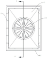
FIG. 1 is a schematic perspective view of the embodiment;
FIG. 2 is a top view of the embodiment;
FIG. 3 is a cross-sectional view taken along A-A in FIG. 2 of the embodiment;
FIG. 4 is a schematic perspective view of a multi-layer sprinkler head according to an embodiment;
FIG. 5 is a cross-sectional view of an embodiment of a multi-layer sprinkler head;
FIG. 6 is an enlarged schematic view at B in FIG. 5 of the embodiment;
FIG. 7 is a first perspective view of a connecting tube according to an embodiment;
FIG. 8 is a schematic perspective view of a second embodiment of a connecting tube;
FIG. 9 is a perspective view of the annular connector of an embodiment;
FIG. 10 is a perspective view of the mounting device and turbine of an embodiment;
FIG. 11 is a schematic perspective view of a mounting device of an embodiment;
fig. 12 is an enlarged schematic view at C in fig. 3 of the embodiment.
The reference numbers in the figures are: 1. an air outlet; 2. a tower body; 3. a filler layer; 4. a dehydrator; 5. a water delivery pipe; 6. a multi-layer sprinkler head; 7. a shower head; 8. a layering device; 9. a sprinkler head; 10. a flat flared portion; 11. a turbofan; 12. a circular tube; 13. a helical blade; 14. a connecting pipe; 15. a hexagonal section; 16. a first water passing tank; 17. an annular connector; 18. a second water passage; 19. an annular dome section; 20. an annular chamfered portion; 21. a first annular groove; 22. a second annular groove; 23. a seal ring; 24. connecting a bolt; 25. a threaded tubular portion; 26. an internal thread; 27. a gasket; 28. a ring sheet; 29. an annular mounting portion; 30. a lower cross; 31. a connecting shaft; 32. a cylinder; 33. a first through groove; 34. an annular limiting part; 35. a stabilizing sheet; 36. a second through groove; 37. a support arm; 38. an upper cross; 39. a support frame; 40. a water collecting tank.
Detailed Description
For further understanding of the features and technical means of the present invention, as well as the specific objects and functions attained by the present invention, the present invention will be described in further detail with reference to the accompanying drawings and detailed description.
Referring to fig. 1 to 12, a cooling tower with low water consumption for producing mixed aromatic hydrocarbon comprises a water collecting tank 40, a tower body 2 fixed in the water collecting tank 40 and having a gas outlet 1 at the top end, a packing layer 3 fixed in the tower body 2 for heat exchange, and a dehydrator 4 fixed in the tower body 2 and located above the packing layer 3, and further comprises:
a plurality of horizontal water pipes 5 which are communicated side by side and fixedly arranged in the tower body 2, each water pipe 5 is positioned between the packing layer 3 and the dehydrator 4, a plurality of layers of sprinkling nozzles 6 which are arranged at intervals and are used for evenly sprinkling hot water to the packing layer 3 are fixedly connected on each water pipe 5, each layer of sprinkling nozzle 6 comprises a pagoda connecting device which is in an inverted state, a sprinkling head 7 which is fixed on the lower end of the pagoda connecting device and a plurality of groups of sprinkling mechanisms which are arranged at intervals along the vertical direction and are communicated with the pagoda connecting device, the pagoda connecting device is formed by fixedly connecting a plurality of groups of layering devices 8 with progressively reduced size along the vertical direction, two adjacent groups of layering devices 8 are communicated with each other, a plurality of groups of sprinkling mechanisms are arranged in one-to-one correspondence with a plurality of groups of layering devices 8, each group of sprinkling mechanisms comprises a plurality of sprinkling heads 9 which are evenly distributed along the circumferential direction of the pagoda connecting device, the end parts of the sprinkler heads 9 are all flat flared parts 10 for spraying large-area water curtains, the flat flared parts 10 of the sprinkler heads 9 positioned at the top are in a horizontal state, and the downward inclination angles of the flat flared parts 10 of the sprinkler heads 9 in a plurality of groups of sprinkler mechanisms are sequentially increased along the vertical downward direction;
the device comprises a mounting device fixed at the air outlet 1 and a turbofan 11 which is coupled with the mounting device and takes updraft as power, wherein the turbofan 11 comprises a vertical circular tube 12 and a plurality of helical blades 13 which are uniformly distributed and fixedly welded on the inner wall of the circular tube 12 along the circumferential direction.
When the device works, hot water is conveyed to a plurality of multilayer water spraying nozzles 6 through a water conveying pipe 5 to be sprayed out, the hot water enters a pagoda connecting device and is conveyed to a plurality of groups of spraying mechanisms, each group of spraying mechanisms comprises a plurality of spraying heads 9 distributed in an annular mode, the coverage range of the sprayed hot water is wide, the end parts of the spraying heads 9 are flat flared parts 10, the hot water sprayed from the spraying heads 9 can be sprayed out through the shape of a water curtain, the contact area of the water curtain with air is increased, the water curtain is beneficial to primary heat exchange with the air before the hot water is sprayed on a packing layer 3, the temperature of the hot water after heat exchange is reduced, the inclined angles of the flat flared parts 10 of the spraying heads 9 in the plurality of groups of spraying mechanisms are sequentially increased along the vertical downward direction, the overlapping of the water curtains sprayed by the plurality of groups of spraying mechanisms is avoided, the hot water is uniformly sprayed on the packing layer 3, and the spraying blind areas of the spraying heads 7 make up the spraying blind areas of the hot water, so that the hot water can be sprayed to the area right below the multilayer sprinkling nozzles 6, the hot water exchanges heat with the air at the packing layer 3, the air enters from the bottom of the tower body 2 and flows out from the air outlet 1, the temperature of the air rises upwards, so that negative pressure is formed below the tower body 2, and due to the existence of the negative pressure, cold air can continuously flow into the tower body 2 from the bottom of the tower body 2, the ascending air flow pushes the turbofan 11 to rotate through the air outlet 1, and the rotation of the turbofan 11 increases the discharge speed of the hot air inside the tower body 2, so that the high temperature air can be discharged in time, and can constantly strike helical blade 13 at the in-process that the air current promoted helical blade 13, the air current constantly strikes helical blade 13 and can make the moisture that contains separate out, and the water of separating can flow downwards until flowing to the catch basin 40 in, reduces the loss of moisture, and hot water can flow to catch basin 40 of below after packing layer 3 and the air heat transfer and carry out reuse.
The layering device 8 comprises:
a vertical connecting pipe 14, a horizontal hexagonal part 15 is formed on the lower end of the vertical connecting pipe 14, the upper end of the connecting pipe 14 is fixedly connected with the lower end of the connecting pipe 14 in the upper layering device 8, the lower end of the connecting pipe 14 is fixedly connected with the upper end of the connecting pipe 14 in the lower layering device 8, and a plurality of first water passing grooves 16 which are uniformly distributed along the circumferential direction are formed on the side wall of the connecting pipe 14;
the annular connecting piece 17 is coaxially arranged with the connecting pipe 14 and fixedly sleeved on the connecting pipe 14, a plurality of second water through grooves 18 which correspond to the first water through grooves 16 one by one are formed on the annular connecting piece 17, the sprinkler heads 9 are fixed on the outer wall of the annular connecting piece 17, and the second water through grooves 18 correspond to the sprinkler heads 9 one by one.
When the hot water enters the layering device 8, the hot water enters the sprinkler heads 9 through the first water passing groove 16 and the second water passing groove 18 in sequence and is sprayed out, when the assembly is needed, a plurality of sprinkler heads 9 of the same group of sprinkler mechanisms are fixedly connected with the annular connecting piece 17, each sprinkler head 9 is communicated with the end part of the corresponding first water passing groove 16, and then the annular connecting piece 17 is fixedly assembled with the connecting pipe 14.
The side wall of the connecting pipe 14 is formed with a coaxial annular circular table portion 19, the lower end of the annular circular table portion 19 is fixedly connected with the upper end of the hexagonal portion 15, the first water passing groove 16 penetrates through the inclined side wall of the annular circular table portion 19, an annular chamfered portion 20 matched with the annular circular table portion 19 is formed on the annular connecting member 17, the second water passing groove 18 penetrates through the annular chamfered portion 20 to be communicated with the corresponding first water passing groove 16, a coaxial first annular groove 21 and a second annular groove 22 positioned below the first annular groove 21 are formed on the side wall of the annular circular table portion 19, the end portion of the first water passing groove 16 is positioned between the first annular groove 21 and the second annular groove 22, sealing rings 23 are arranged in the first annular groove 21 and the second annular groove 22, the annular chamfered portion 20 abuts against the two sealing rings 23, and the annular connecting member 17 is fixedly connected with the annular circular table portion 19 through a plurality of vertical connecting bolts 24, the connecting bolt 24 passes through the annular connecting piece 17 and is screwed and fixed with the annular circular table part 19.
When the layered device 8 is assembled, the two sealing rings 23 are respectively clamped into the first annular groove 21 and the second annular groove 22, the annular connecting piece 17 is sleeved in from the upper end of the connecting pipe 14, the annular chamfer part 20 is aligned to the annular circular truncated cone part 19, the connecting bolts 24 penetrate through the annular connecting piece 17 and are screwed with the annular circular truncated cone part 19, the connecting bolts 24 are continuously screwed, the distance between the annular chamfer part 20 and the annular circular truncated cone part 19 is reduced, the annular chamfer part 20 can tightly abut against the two sealing rings 23, hot water cannot leak, and the assembly of the layered device 8 is completed.
The upper end shaping of connecting pipe 14 has the screwed pipe portion 25 of coaxial line, and the external diameter of screwed pipe portion 25 is less than the external diameter of connecting pipe 14, the shaping has internal thread 26 on the lower extreme of connecting pipe 14, and internal thread 26 is located the below of first water trough 16, screwed pipe portion 25 connects fixedly with the internal thread 26 of the connecting pipe 14 that is located the top soon, and screwed pipe portion 25 goes up the cover and is equipped with sealed pad 27, and the screwed pipe portion 25 of the connecting pipe 14 that is located the layering device 8 of the top is connected with raceway 5 through the tee bend, and the internal thread 26 of the connecting pipe 14 of the layering device 8 that is located the bottommost connects fixedly with gondola water faucet 7 soon, and wherein the external diameter of the screwed pipe portion 25 of connecting pipe 14 that connects fixedly with the tee bend is unanimous with the external diameter of connecting pipe 14.
When the plurality of component layer devices 8 are assembled, the spiral part of the connecting pipe 14 is screwed into the lower end of the other connecting pipe 14, the hexagonal part 15 is used for being clamped by a wrench, the threaded pipe part 25 is screwed into the internal thread 26 continuously until the two ends of the sealing gasket 27 are respectively abutted against the two adjacent connecting pipes 14, and the plurality of component layer devices 8 are assembled into the pagoda connecting device.
Installation device includes the ring piece 28 with 12 coaxial lines of pipe, and the bottom shaping of ring piece 28 has the coaxial line and gas outlet 1 fixed connection's annular installation department 29, and fixed connection has horizontally lower cross 30 on the ring piece 28, has the vertical connecting axle 31 with the ring piece 28 coaxial line on the cross 30 down, connecting axle 31 is located in the middle of a plurality of helical blade 13, the fixed cover is equipped with the drum 32 of the inversion of coaxial line on the connecting axle 31, and the upper end shaping of drum 32 has the first logical groove 33 of a plurality of that supplies the air current to pass through, the top of drum 32 and the lower extreme fixed connection of pipe 12, cross 30 is located drum 32 down, the shaping has the coaxial line and the spacing portion 34 of the annular of drum 32 outer wall contact on the ring piece 28 top.
The ascending air current upwards passes through gas outlet 1, lower cross 30 and first logical groove 33 and gets into turbofan 11, and gas blows turbofan 11 and rotates, and turbofan 11 drives the drum 32 and rotates, and drum 32 drives connecting axle 31 and rotates, and the outer wall of drum 32 contacts with annular spacing portion 34, because of drum 32 needs to rotate, so the outer wall of drum 32 can not be too closely with the contact of annular spacing portion 34, but annular spacing portion 34 can reduce the gas volume of following the play between turbofan 11 and ring piece 28.
The installation device is still including fixed horizontally stabilizer blade 35 of establishing on connecting axle 31 of cover, the upper end fixed connection of stabilizer blade 35 and pipe 12, and the shaping has a plurality of second through slot 36 that the air feed stream passes through on the stabilizer blade 35, four vertical support arms 37 along circumferencial direction evenly distributed of fixedly connected with on the ring piece 28, the spacing portion 34 of annular is located four support arms 37's inboard, it has horizontally last cross 38 to peg graft on the upper end of connecting axle 31, goes up cross 38 and is located the top of turbofan 11, go up four ends of cross 38 respectively with four support arms 37's upper end fixed connection.
The lower end of the connecting shaft 31 is coupled to the lower cross 30, and the connecting shaft 31 may be inclined, so that the upper cross 38 and the plurality of supporting arms 37 are required to maintain the stability of the connecting shaft 31, and the stabilizing plate 35 is required to maintain the stability between the turbofan 11 and the connecting shaft 31.
The bottom of the tower body 2 is fixed in a water collecting tank 40 through a plurality of vertical supporting frames 39, and cold air enters the tower body 2 from the lower part of the tower body 2.
The working principle is as follows: when the equipment works, hot water is conveyed to a plurality of multilayer water spraying nozzles 6 through a water conveying pipe 5 to be sprayed, the hot water enters a pagoda connecting device and is conveyed to a plurality of groups of spraying mechanisms, each group of spraying mechanisms comprises a plurality of spraying heads 9 which are distributed annularly, the coverage range of the sprayed hot water is wide, the end parts of the spraying heads 9 are flat flaring parts, the hot water is conveyed to the spraying heads 9 through a first water through groove 16 and a second water through groove 18, the hot water sprayed from the spraying heads 9 can be sprayed out through the shape of water curtains, the contact area between the water curtains and air is increased, the water curtains are beneficial to carrying out primary heat exchange with the air before the hot water is sprayed on the packing layer 3, the flat flaring parts 10 of the spraying heads 9 in the plurality of groups of spraying mechanisms are sequentially increased along the vertical downward inclination angle, the overlapping of the water curtains sprayed by the plurality of groups of spraying mechanisms is avoided, and the hot water is uniformly sprayed on the packing layer 3 in the downward direction, the shower head 7 makes up the blind area of hot water spraying, so that the hot water can be sprayed to the area right below the multilayer shower nozzle 6, the hot water exchanges heat with air in the packing layer 3, the air enters from the bottom of the tower body 2 and flows out from the air outlet 1, the air stably rises and rises, so that negative pressure is formed below the tower body 2, and due to the existence of the negative pressure, cold air can continuously flow into the tower body 2 from the bottom of the tower body 2, the ascending air flow pushes the turbofan 11 to rotate through the air outlet 1, and the rotation of the turbofan 11 increases the discharge speed of the hot air inside the tower body 2, so that the high temperature air can be discharged in time, can constantly strike helical blade 13 at the in-process that the air current promoted helical blade 13, the air current constantly strikes helical blade 13 and can make the moisture that contains separate out, reduces the moisture loss, and hot water can flow the catch basin 40 of below and use again after packing layer 3 and the air heat transfer.
The above examples, which are intended to represent only one or more embodiments of the present invention, are described in greater detail and with greater particularity, and are not to be construed as limiting the scope of the invention. It should be noted that various changes and modifications can be made by those skilled in the art without departing from the spirit of the invention, and these changes and modifications are all within the scope of the invention. Therefore, the protection scope of the present patent shall be subject to the appended claims.
Claims (7)
1. The utility model provides a low consumption water cooling tower of mixed aromatic production usefulness, includes catch basin (40), fixes tower body (2) that have gas outlet (1) on just the top in catch basin (40), fixes packing layer (3) that are used for the heat transfer in tower body (2) and fixes dehydrator (4) that just are located packing layer (3) top in tower body (2), its characterized in that still includes:
a plurality of horizontal water pipes (5) which are communicated side by side and fixedly arranged in the tower body (2), each water pipe (5) is positioned between the packing layer (3) and the dehydrator (4), a plurality of layers of sprinkling nozzles (6) which are arranged at intervals and are used for evenly sprinkling hot water to the packing layer (3) are fixedly connected on each water pipe (5), each layer of sprinkling nozzle (6) comprises a pagoda connecting device which is in an inverted state, a sprinkling head (7) which is fixed on the lower end of the pagoda connecting device and a plurality of groups of sprinkling mechanisms which are arranged at intervals along the vertical direction and communicated with the pagoda connecting device, the pagoda connecting device is formed by fixedly connecting a plurality of groups of layering devices (8) with progressively reduced size along the vertical direction, two adjacent groups of layering devices (8) are mutually communicated, and a plurality of groups of sprinkling mechanisms are arranged in one-to-one correspondence with the plurality of the component layering devices (8), each group of spraying mechanisms comprises a plurality of spraying heads (9) which are uniformly distributed along the circumferential direction of the pagoda connecting device, the end parts of the spraying heads (9) are flat flared parts (10) which are used for spraying a large-area water curtain, the flat flared parts (10) of the spraying heads (9) positioned at the top are in a horizontal state, and the downward inclination angles of the flat flared parts (10) of the spraying heads (9) in the plurality of groups of spraying mechanisms are sequentially increased along the vertical downward direction;
the device comprises a mounting device fixed at the air outlet (1) and a turbofan (11) which is coupled with the mounting device and takes ascending air flow as power, wherein the turbofan (11) comprises a vertical round pipe (12) and a plurality of helical blades (13) which are uniformly distributed and fixedly welded on the inner wall of the round pipe (12) along the circumferential direction.
2. The cooling tower with low water consumption for the production of mixed aromatics according to claim 1, characterized in that the stratification means (8) comprises:
the lower end of the vertical connecting pipe (14) is provided with a horizontal hexagonal part (15), the upper end of the connecting pipe (14) is fixedly connected with the lower end of the connecting pipe (14) in the upper layering device (8), the lower end of the connecting pipe (14) is fixedly connected with the upper end of the connecting pipe (14) in the lower layering device (8), and the side wall of the connecting pipe (14) is provided with a plurality of first water passing grooves (16) which are uniformly distributed along the circumferential direction;
the fixed sleeve that sets up with connecting pipe (14) coaxial line establishes annular connecting piece (17) on connecting pipe (14), and the shaping has a plurality of second water trough (18) with a plurality of first water trough (16) one-to-one on annular connecting piece (17), sprinkler head (9) are fixed on the outer wall of annular connecting piece (17), a plurality of second water trough (18) and a plurality of sprinkler head (9) one-to-one.
3. The cooling tower with low water consumption for producing mixed aromatic hydrocarbon according to claim 2, wherein the sidewall of the connecting pipe (14) is formed with a coaxial annular boss portion (19), the lower end of the annular boss portion (19) is fixedly connected with the upper end of the hexagonal portion (15), the first water passing groove (16) passes through the inclined sidewall of the annular boss portion (19), the annular connecting member (17) is formed with an annular chamfered portion (20) fitted with the annular boss portion (19), the second water passing groove (18) passes through the annular chamfered portion (20) to communicate with the corresponding first water passing groove (16), the sidewall of the annular boss portion (19) is formed with a coaxial first annular groove (21) and a second annular groove (22) located below the first annular groove (21), and the end of the first water passing groove (16) is located between the first annular groove (21) and the second annular groove (22), all be equipped with sealing washer (23) in first annular groove (21) and second annular groove (22), and annular chamfer portion (20) are contradicted on two sealing washers (23), ring connecting piece (17) are tied (24) and annular boss portion (19) fixed connection through the vertical connection of a plurality of, it is fixed with annular boss portion (19) to pass ring connecting piece (17) soon in connection bolt (24).
4. The cooling tower with low water consumption for producing mixed aromatic hydrocarbons according to claim 2, wherein a coaxial threaded pipe portion (25) is formed at the upper end of the connecting pipe (14), the outer diameter of the threaded pipe portion (25) is smaller than the outer diameter of the connecting pipe (14), an internal thread (26) is formed at the lower end of the connecting pipe (14), the internal thread (26) is located below the first water trough (16), the threaded pipe portion (25) is screwed and fixed with the internal thread (26) of the connecting pipe (14) located above, a sealing gasket (27) is sleeved on the threaded pipe portion (25), the threaded pipe portion (25) of the connecting pipe (14) of the uppermost layering device (8) is connected with the water pipe (5) through a tee joint, and the internal thread (26) of the connecting pipe (14) of the lowermost layering device (8) is screwed and fixed with the shower head (7), wherein the outer diameter of the threaded pipe part (25) of the connecting pipe (14) screwed and fixed with the tee is consistent with the outer diameter of the connecting pipe (14).
5. The cooling tower with low water consumption for producing the mixed aromatic hydrocarbon according to claim 1, wherein the mounting device comprises a ring piece (28) which is coaxial with the circular tube (12), a ring-shaped mounting part (29) which is coaxial with the circular tube (28) and is fixedly connected with the air outlet (1) is formed at the bottom end of the ring piece (28), a horizontal lower cross (30) is fixedly connected onto the ring piece (28), a vertical connecting shaft (31) which is coaxial with the ring piece (28) is coupled onto the lower cross (30), the connecting shaft (31) is positioned among the plurality of helical blades (13), an inverted cylinder (32) which is coaxial with the circular tube is fixedly sleeved on the connecting shaft (31), a plurality of first through grooves (33) for air flow to pass through are formed at the upper end of the cylinder (32), the top end of the cylinder (32) is fixedly connected with the lower end of the circular tube (12), and the lower cross (30) is positioned in the cylinder (32), and a coaxial annular limiting part (34) which is contacted with the outer wall of the cylinder (32) is formed on the top end of the ring piece (28).
6. The cooling tower with low water consumption for producing mixed aromatic hydrocarbon according to claim 5, wherein the mounting device further comprises a horizontal stabilizing piece (35) fixedly sleeved on the connecting shaft (31), the stabilizing piece (35) is fixedly connected with the upper end of the circular tube (12), a plurality of second through grooves (36) for air flow to pass through are formed in the stabilizing piece (35), four vertical supporting arms (37) uniformly distributed along the circumferential direction are fixedly connected to the ring piece (28), the annular limiting part (34) is located on the inner side of the four supporting arms (37), a horizontal upper cross (38) is connected to the upper end of the connecting shaft (31), the upper cross (38) is located above the turbofan (11), and four ends of the upper cross (38) are respectively fixedly connected with the upper ends of the four supporting arms (37).
7. The cooling tower with low water consumption for producing the mixed aromatic hydrocarbon according to claim 1, wherein the bottom of the tower body (2) is fixed in a water collecting tank (40) through a plurality of vertical supporting frames (39), and cold air enters the tower body (2) from the lower part of the tower body (2).
Priority Applications (1)
| Application Number | Priority Date | Filing Date | Title |
|---|---|---|---|
| CN202210958028.0A CN115031550B (en) | 2022-08-11 | 2022-08-11 | Low water consumption cooling tower for producing mixed aromatic hydrocarbon |
Applications Claiming Priority (1)
| Application Number | Priority Date | Filing Date | Title |
|---|---|---|---|
| CN202210958028.0A CN115031550B (en) | 2022-08-11 | 2022-08-11 | Low water consumption cooling tower for producing mixed aromatic hydrocarbon |
Publications (2)
| Publication Number | Publication Date |
|---|---|
| CN115031550A true CN115031550A (en) | 2022-09-09 |
| CN115031550B CN115031550B (en) | 2022-11-08 |
Family
ID=83130385
Family Applications (1)
| Application Number | Title | Priority Date | Filing Date |
|---|---|---|---|
| CN202210958028.0A Active CN115031550B (en) | 2022-08-11 | 2022-08-11 | Low water consumption cooling tower for producing mixed aromatic hydrocarbon |
Country Status (1)
| Country | Link |
|---|---|
| CN (1) | CN115031550B (en) |
Citations (6)
| Publication number | Priority date | Publication date | Assignee | Title |
|---|---|---|---|---|
| JP2007023962A (en) * | 2005-07-20 | 2007-02-01 | Fuji Electric Systems Co Ltd | Axial exhaust type steam turbine device |
| CN102419113A (en) * | 2011-12-20 | 2012-04-18 | 常州蒙特环境科技有限公司 | Cooling tower |
| CN105004197A (en) * | 2015-07-31 | 2015-10-28 | 重庆骏成机械配件有限公司 | Cooling tower |
| CN111220000A (en) * | 2020-03-09 | 2020-06-02 | 深圳市辰诺节能科技有限公司 | Water vector suspension atomization cooling tower |
| CN211060726U (en) * | 2019-09-09 | 2020-07-21 | 江苏五明冷却塔有限公司 | Spray head of cooling tower |
| CN213747976U (en) * | 2020-11-13 | 2021-07-20 | 广州单梁全钢冷却塔设备有限公司 | High-efficient all-steel cooling tower for computer lab |
-
2022
- 2022-08-11 CN CN202210958028.0A patent/CN115031550B/en active Active
Patent Citations (6)
| Publication number | Priority date | Publication date | Assignee | Title |
|---|---|---|---|---|
| JP2007023962A (en) * | 2005-07-20 | 2007-02-01 | Fuji Electric Systems Co Ltd | Axial exhaust type steam turbine device |
| CN102419113A (en) * | 2011-12-20 | 2012-04-18 | 常州蒙特环境科技有限公司 | Cooling tower |
| CN105004197A (en) * | 2015-07-31 | 2015-10-28 | 重庆骏成机械配件有限公司 | Cooling tower |
| CN211060726U (en) * | 2019-09-09 | 2020-07-21 | 江苏五明冷却塔有限公司 | Spray head of cooling tower |
| CN111220000A (en) * | 2020-03-09 | 2020-06-02 | 深圳市辰诺节能科技有限公司 | Water vector suspension atomization cooling tower |
| CN213747976U (en) * | 2020-11-13 | 2021-07-20 | 广州单梁全钢冷却塔设备有限公司 | High-efficient all-steel cooling tower for computer lab |
Also Published As
| Publication number | Publication date |
|---|---|
| CN115031550B (en) | 2022-11-08 |
Similar Documents
| Publication | Publication Date | Title |
|---|---|---|
| CN210278725U (en) | Hydrochloric acid exhaust gas washing tower | |
| CN203209259U (en) | Hemispherical water sprayer | |
| CN212119457U (en) | Spiral airflow spray tower | |
| CN115031550B (en) | Low water consumption cooling tower for producing mixed aromatic hydrocarbon | |
| CN210206372U (en) | Polyvinyl alcohol drying tail gas purification system | |
| CN208032248U (en) | A kind of eddy flow tower | |
| CN112474087B (en) | Liquid distributor, multistage efficient distributor and washing liquid spraying method | |
| CN215332784U (en) | Polymer dispersion devices | |
| CN204234254U (en) | A kind of spraying equipment for loading shovel | |
| CN208161254U (en) | A kind of inverse spray head and the heavy caliber of spraying of heavy caliber is against spray rinsing device | |
| CN208082421U (en) | A kind of fluidized bed granulation seed-coating machine | |
| CN207356785U (en) | A kind of gas and oil separating plant | |
| CN207941223U (en) | A kind of fixed ammonia destilling tower | |
| CN207391363U (en) | Raw gas purifying device | |
| CN220853208U (en) | Circulating water cooling tower | |
| CN220025611U (en) | Fluidized bed coating device for pharmacy | |
| CN218308601U (en) | Fire-retardant gravity type becomes rotatory water distribution shower nozzle of flow | |
| CN211290007U (en) | Complete set of steel pipe coal economizer | |
| CN216093039U (en) | Denitration device used in cement kiln | |
| CN215311166U (en) | Foam dust removal cooling device | |
| CN220276584U (en) | Industrial waste gas spraying equipment | |
| CN219384917U (en) | Double-nozzle rotational flow aeration device with optimized structure | |
| CN215524239U (en) | Ammonia condensation cooler | |
| CN209613332U (en) | A kind of novel high-pressure fog pipe | |
| CN210434709U (en) | High-efficient condensation shower nozzle structure of vacuum salt manufacturing |
Legal Events
| Date | Code | Title | Description |
|---|---|---|---|
| PB01 | Publication | ||
| PB01 | Publication | ||
| SE01 | Entry into force of request for substantive examination | ||
| SE01 | Entry into force of request for substantive examination | ||
| GR01 | Patent grant | ||
| GR01 | Patent grant | ||
| PP01 | Preservation of patent right |
Effective date of registration: 20240125 Granted publication date: 20221108 |
|
| PP01 | Preservation of patent right |