CN114992468A - Remote medical diagnosis system based on Internet of things - Google Patents
Remote medical diagnosis system based on Internet of things Download PDFInfo
- Publication number
- CN114992468A CN114992468A CN202210781288.5A CN202210781288A CN114992468A CN 114992468 A CN114992468 A CN 114992468A CN 202210781288 A CN202210781288 A CN 202210781288A CN 114992468 A CN114992468 A CN 114992468A
- Authority
- CN
- China
- Prior art keywords
- plate
- rod
- plates
- driving mechanism
- things
- Prior art date
- Legal status (The legal status is an assumption and is not a legal conclusion. Google has not performed a legal analysis and makes no representation as to the accuracy of the status listed.)
- Withdrawn
Links
- 238000003745 diagnosis Methods 0.000 title claims abstract description 36
- 230000007246 mechanism Effects 0.000 claims abstract description 67
- 230000005540 biological transmission Effects 0.000 claims abstract description 21
- 230000002457 bidirectional effect Effects 0.000 claims description 20
- 238000012545 processing Methods 0.000 claims description 6
- 230000033001 locomotion Effects 0.000 abstract description 13
- 238000009434 installation Methods 0.000 abstract description 8
- 201000010099 disease Diseases 0.000 description 11
- 208000037265 diseases, disorders, signs and symptoms Diseases 0.000 description 11
- 238000000034 method Methods 0.000 description 11
- 230000008569 process Effects 0.000 description 11
- 238000010586 diagram Methods 0.000 description 4
- 230000000694 effects Effects 0.000 description 4
- 208000011580 syndromic disease Diseases 0.000 description 4
- 230000008094 contradictory effect Effects 0.000 description 2
- 238000011161 development Methods 0.000 description 2
- 238000005516 engineering process Methods 0.000 description 2
- 230000002159 abnormal effect Effects 0.000 description 1
- 230000009286 beneficial effect Effects 0.000 description 1
- 238000013461 design Methods 0.000 description 1
- 238000001514 detection method Methods 0.000 description 1
- 238000006073 displacement reaction Methods 0.000 description 1
- 238000007689 inspection Methods 0.000 description 1
- 238000012423 maintenance Methods 0.000 description 1
- 230000006855 networking Effects 0.000 description 1
- 230000002265 prevention Effects 0.000 description 1
- 230000009466 transformation Effects 0.000 description 1
- 230000007704 transition Effects 0.000 description 1
Images


Classifications
-
- F—MECHANICAL ENGINEERING; LIGHTING; HEATING; WEAPONS; BLASTING
- F16—ENGINEERING ELEMENTS AND UNITS; GENERAL MEASURES FOR PRODUCING AND MAINTAINING EFFECTIVE FUNCTIONING OF MACHINES OR INSTALLATIONS; THERMAL INSULATION IN GENERAL
- F16M—FRAMES, CASINGS OR BEDS OF ENGINES, MACHINES OR APPARATUS, NOT SPECIFIC TO ENGINES, MACHINES OR APPARATUS PROVIDED FOR ELSEWHERE; STANDS; SUPPORTS
- F16M11/00—Stands or trestles as supports for apparatus or articles placed thereon ; Stands for scientific apparatus such as gravitational force meters
- F16M11/02—Heads
- F16M11/04—Means for attachment of apparatus; Means allowing adjustment of the apparatus relatively to the stand
-
- A—HUMAN NECESSITIES
- A61—MEDICAL OR VETERINARY SCIENCE; HYGIENE
- A61B—DIAGNOSIS; SURGERY; IDENTIFICATION
- A61B5/00—Measuring for diagnostic purposes; Identification of persons
-
- F—MECHANICAL ENGINEERING; LIGHTING; HEATING; WEAPONS; BLASTING
- F16—ENGINEERING ELEMENTS AND UNITS; GENERAL MEASURES FOR PRODUCING AND MAINTAINING EFFECTIVE FUNCTIONING OF MACHINES OR INSTALLATIONS; THERMAL INSULATION IN GENERAL
- F16M—FRAMES, CASINGS OR BEDS OF ENGINES, MACHINES OR APPARATUS, NOT SPECIFIC TO ENGINES, MACHINES OR APPARATUS PROVIDED FOR ELSEWHERE; STANDS; SUPPORTS
- F16M11/00—Stands or trestles as supports for apparatus or articles placed thereon ; Stands for scientific apparatus such as gravitational force meters
- F16M11/02—Heads
- F16M11/04—Means for attachment of apparatus; Means allowing adjustment of the apparatus relatively to the stand
- F16M11/043—Allowing translations
- F16M11/045—Allowing translations adapted to left-right translation movement
-
- F—MECHANICAL ENGINEERING; LIGHTING; HEATING; WEAPONS; BLASTING
- F16—ENGINEERING ELEMENTS AND UNITS; GENERAL MEASURES FOR PRODUCING AND MAINTAINING EFFECTIVE FUNCTIONING OF MACHINES OR INSTALLATIONS; THERMAL INSULATION IN GENERAL
- F16M—FRAMES, CASINGS OR BEDS OF ENGINES, MACHINES OR APPARATUS, NOT SPECIFIC TO ENGINES, MACHINES OR APPARATUS PROVIDED FOR ELSEWHERE; STANDS; SUPPORTS
- F16M11/00—Stands or trestles as supports for apparatus or articles placed thereon ; Stands for scientific apparatus such as gravitational force meters
- F16M11/02—Heads
- F16M11/04—Means for attachment of apparatus; Means allowing adjustment of the apparatus relatively to the stand
- F16M11/043—Allowing translations
- F16M11/048—Allowing translations adapted to forward-backward translation movement
-
- F—MECHANICAL ENGINEERING; LIGHTING; HEATING; WEAPONS; BLASTING
- F16—ENGINEERING ELEMENTS AND UNITS; GENERAL MEASURES FOR PRODUCING AND MAINTAINING EFFECTIVE FUNCTIONING OF MACHINES OR INSTALLATIONS; THERMAL INSULATION IN GENERAL
- F16M—FRAMES, CASINGS OR BEDS OF ENGINES, MACHINES OR APPARATUS, NOT SPECIFIC TO ENGINES, MACHINES OR APPARATUS PROVIDED FOR ELSEWHERE; STANDS; SUPPORTS
- F16M11/00—Stands or trestles as supports for apparatus or articles placed thereon ; Stands for scientific apparatus such as gravitational force meters
- F16M11/02—Heads
- F16M11/18—Heads with mechanism for moving the apparatus relatively to the stand
-
- Y—GENERAL TAGGING OF NEW TECHNOLOGICAL DEVELOPMENTS; GENERAL TAGGING OF CROSS-SECTIONAL TECHNOLOGIES SPANNING OVER SEVERAL SECTIONS OF THE IPC; TECHNICAL SUBJECTS COVERED BY FORMER USPC CROSS-REFERENCE ART COLLECTIONS [XRACs] AND DIGESTS
- Y02—TECHNOLOGIES OR APPLICATIONS FOR MITIGATION OR ADAPTATION AGAINST CLIMATE CHANGE
- Y02A—TECHNOLOGIES FOR ADAPTATION TO CLIMATE CHANGE
- Y02A90/00—Technologies having an indirect contribution to adaptation to climate change
- Y02A90/10—Information and communication technologies [ICT] supporting adaptation to climate change, e.g. for weather forecasting or climate simulation
Landscapes
- Engineering & Computer Science (AREA)
- General Engineering & Computer Science (AREA)
- Mechanical Engineering (AREA)
- Life Sciences & Earth Sciences (AREA)
- Health & Medical Sciences (AREA)
- Biomedical Technology (AREA)
- Biophysics (AREA)
- Pathology (AREA)
- Physics & Mathematics (AREA)
- Heart & Thoracic Surgery (AREA)
- Medical Informatics (AREA)
- Molecular Biology (AREA)
- Surgery (AREA)
- Animal Behavior & Ethology (AREA)
- General Health & Medical Sciences (AREA)
- Public Health (AREA)
- Veterinary Medicine (AREA)
- Transmission Devices (AREA)
Abstract
The invention relates to a remote medical diagnosis system based on the Internet of things, which comprises a base, wherein two protruding plates are movably arranged on the base through an electric telescopic mechanism and are parallel to each other, transverse plates are arranged on the side parts of the two protruding plates, the transverse plates are connected with a thread driving mechanism through two groups of fork type supporting mechanisms, the thread driving mechanism is arranged between the two protruding plates, one side of each transverse plate, far away from the corresponding protruding plate, is fixedly provided with an installation part, the installation part is U-shaped and is vertical to the transverse plates, a deflection plate is rotatably arranged on the installation part, a rotating shaft of the deflection plate is connected with a reciprocating driving mechanism arranged on the installation part, the reciprocating driving mechanism is connected with the thread driving mechanism through a transmission mechanism, and finally, the horizontal movement and the reciprocating swing of a scanner are carried out simultaneously, greatly improves the scanning range of the scanner to the body of the patient and brings convenience to the use.
Description
Technical Field
The invention relates to the technical field of medical equipment, in particular to a remote medical diagnosis system based on the Internet of things.
Background
The medical diagnosis refers to the process of finding out the affected part and degree and determining the disease name when the human body is in an abnormal state, and the diagnosis process is a chain formed by diagnosing, diagnosing the disease, diagnosing the syndrome and the person, the disease, the type and the syndrome so as to form a unified whole.
This requires that the doctor be able to grasp the disease comprehensively, reveal the nature of the disease as much as possible, and study all of its relationships and "media"; secondly, revealing the development and movement of diseases, analyzing the essence of the diseases by using historical attitudes, and grasping the transformation and transition rule from one person, disease, type and syndrome to another person, disease, type and syndrome; thirdly, the contradictory nature of the disease must be revealed, and a true diagnosis is only achieved if the contradictory nature of the disease is mastered; fourthly, the diagnosis must include prevention and treatment plans and medical practices, which are also the judgment standard for the correctness of the diagnosis, and all the diagnosis bases are clinical practices.
With the rapid development of science and technology, more and more technical means for medical diagnosis are provided, wherein advanced instruments are used for scanning and examining the body of a patient, which can bring great help to the diagnosis work of doctors, however, at present, when scanning and examining, the scanning and examining range of the instruments is very limited, which brings inconvenience to the use.
Disclosure of Invention
The invention aims to provide a remote medical diagnosis system based on the Internet of things, so as to solve the problems in the background technology.
In order to achieve the purpose, the invention provides the following technical scheme: a remote medical diagnosis system based on the Internet of things comprises a base, wherein two protruding plates are movably arranged on the base through an electric telescopic mechanism and are parallel to each other;
the lateral parts of the two protruding plates are provided with transverse plates, the transverse plates are connected with a thread driving mechanism through two groups of fork type supporting mechanisms, and the thread driving mechanism is arranged between the two protruding plates; an installation part is fixedly arranged on one side of the transverse plate, which is far away from the protruding plate, the installation part is U-shaped and is vertical to the transverse plate, a deflection plate is rotatably installed on the installation part, a rotating shaft of the deflection plate is connected with a reciprocating driving mechanism arranged on the installation part, and the reciprocating driving mechanism is connected with the thread driving mechanism through a transmission mechanism; the one end that the diaphragm was kept away from to the deflector is installed and is used for carrying out the scanner that detects to the patient, just still install on the deflector with scanner electric connection's data processing device.
As a further scheme of the invention: electric telescopic machanism includes fixed mounting and is in deflector on the base, setting are in deflector extension plate and install in a plurality of electric telescopic handle of deflector lateral part, two the protruding board fixed mounting be in the lateral part of extension plate, the deflector with the base is mutually perpendicular, and its inside cavity, and with the sliding sleeve of extension plate closes, the lateral part of extension plate with electric telescopic handle's movable end is fixed.
As a still further scheme of the invention: screw thread actuating mechanism installs two including rotating two-way lead screw, fixed mounting between the protruding board are two guide bar and setting between the protruding board with two-way lead screw with two screw plates on the guide bar, the screw plate with guide bar sliding connection, simultaneously two-way lead screw threaded connection, and one of them driving motor is still installed to the lateral part of protruding board, driving motor's output with two-way lead screw connects.
As a still further scheme of the invention: fork supporting mechanism includes with two sets of rotating-structure that the screwed plate is connected with connect one of them a set of rotating-structure with the structure of stepping down of diaphragm, rotating-structure includes first connecting rod and second connecting rod, first connecting rod with the midpoint rotation of second connecting rod is connected, and is two sets of first connecting rod among the rotating-structure rotates with the tip of second connecting rod to be connected, and is close to the tip of first connecting rod among the rotating-structure of screwed plate and second connecting rod rotates with two screwed plates respectively and is connected.
As a still further scheme of the invention: the rotating structure comprises a first supporting rod and a second supporting rod, one end of the first supporting rod is rotatably connected with the transverse plate, the other end of the first supporting rod is rotatably connected with the end portion of the second connecting rod, the other end of the second supporting rod is rotatably connected with the end portion of the first connecting rod, a strip-shaped sliding groove is formed in the first supporting rod, a cylinder is fixedly installed at the middle point of the second supporting rod, and the cylinder penetrates through the strip-shaped sliding groove and is slidably connected with the first supporting rod.
As a still further scheme of the invention: fixed mounting has the combination plate on the installed part, the combination plate is "U" shape setting, reciprocating drive mechanism is including installing rotating assembly on the combination plate and installing meshing sliding assembly on the installed part, rotating assembly installs including rotating disc on the combination plate, the axis of rotation of disc with drive mechanism connects, and its eccentric department fixed mounting has the cylinder.
As a still further scheme of the invention: meshing sliding assembly includes fixed mounting two horizontal poles on the installed part and slides and set up two reciprocating plate on the horizontal pole, fixed mounting has spacing slat on the reciprocating plate, seted up the recess on the spacing slat, the cylinder stretch into extremely in the recess with spacing slat sliding connection, one of reciprocating plate is served and is fixed with the rack board, just fixed mounting has the gear in the axis of rotation of deflection board, the gear with the tooth meshing on the rack board.
As a still further scheme of the invention: drive mechanism includes that the head end passes through the first movable rod and the second movable rod that the shaft member rotated the connection, the tail end of first movable rod is installed with rotating the connecting axle of extension board lateral part rotates to be connected, the tail end of second movable rod with the axis of rotation of disc rotates to be connected, the shaft member with connect through first drive belt between the connecting axle, the shaft member still through the second drive belt with the rotation axis connection of disc, the one end of connecting axle pass through bevel gear group with two-way lead screw is connected.
Compared with the prior art, the invention has the beneficial effects that: the invention has novel design, a doctor controls the thread driving mechanism to work through the Internet of things, the thread driving mechanism drives the transverse plate to do linear motion in the horizontal reverse direction through the fork type supporting mechanism, so that the scanner moves from one end of a sickbed to the other end in the examination and diagnosis process, and in the process, the thread driving mechanism also drives the reciprocating driving mechanism to move through the transmission mechanism, so that the reciprocating driving mechanism drives the deflection plate to continuously swing back and forth in the horizontal direction, thus the horizontal motion and the reciprocating swing of the scanner are simultaneously carried out, the scanning range of the scanner on the body of a patient is greatly improved, and the use is facilitated.
Drawings
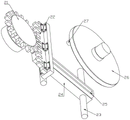
FIG. 1 is an isometric view of one embodiment of an Internet of things-based remote medical diagnostic system.
Fig. 2 is a schematic structural diagram of an embodiment of the remote medical diagnosis system based on the internet of things.
Fig. 3 is a schematic structural diagram of another aspect of an embodiment of a remote medical diagnosis system based on the internet of things.
Fig. 4 is a schematic structural diagram of another aspect of an embodiment of the remote medical diagnosis system based on the internet of things.
Fig. 5 is an enlarged view of a structure at a in fig. 3.
Fig. 6 is an exploded view of the reciprocating drive mechanism in one embodiment of an internet of things based telemedicine diagnostic system.
Fig. 7 is a schematic structural diagram of a fork support mechanism in an embodiment of the internet-of-things-based remote medical diagnosis system.
In the figure: 1. a base; 2. a guide plate; 3. an extension plate; 4. a projecting plate; 5. a scanner; 6. a data processing device; 7. a drive motor; 8. a bidirectional screw rod; 9. a guide bar; 10. a thread plate; 11. a first link; 12. a second link; 13. a transverse plate; 14. a first support bar; 15. a second support bar; 16. a strip-shaped chute; 17. a cylinder; 18. a mounting member; 19. a deflection plate; 20. assembling a plate member; 21. a gear; 22. a rack plate; 23. a cross bar; 24. a reciprocating plate; 25. a limiting batten; 26. a disc; 27. a cylinder; 28. a shaft member; 29. a first movable bar; 30. a second movable bar; 31. a first drive belt; 32. a second belt; 33. an electric telescopic rod; 34. a bevel gear set.
Detailed Description
The technical solutions in the embodiments of the present invention will be clearly and completely described below with reference to the drawings in the embodiments of the present invention, and it is obvious that the described embodiments are only a part of the embodiments of the present invention, and not all of the embodiments. All other embodiments, which can be derived by a person skilled in the art from the embodiments given herein without making any creative effort, shall fall within the protection scope of the present invention.
In addition, an element of the present invention may be said to be "fixed" or "disposed" to another element, either directly on the other element or with intervening elements present. When an element is referred to as being "connected" to another element, it can be directly connected to the other element or intervening elements may also be present. The terms "vertical," "horizontal," "left," "right," and the like as used herein are for illustrative purposes only and do not represent the only embodiments.
Referring to fig. 1 to 7, in an embodiment of the present invention, an internet of things-based remote medical diagnosis system includes a base 1, two protruding plates 4 are movably disposed on the base 1 through an electric telescopic mechanism, and the two protruding plates 4 are parallel to each other.
It should be noted that, in actual use, the system needs to be used in cooperation with a hospital bed, a patient to be examined and diagnosed with an illness can lie on the hospital bed, the system is located at one end of the hospital bed, and the base 1 is fixed to the bottom surface of the hospital bed.
The side parts of the two protruding plates 4 are provided with transverse plates 13, the transverse plates 13 are connected with a thread driving mechanism through two groups of fork type supporting mechanisms, and the thread driving mechanism is installed between the two protruding plates 4.
The transverse plate 13 is fixedly provided with a mounting piece 18 at one side far away from the projecting plate 4, the mounting piece 18 and the transverse plate 13 can be directly and integrally formed, and fasteners such as threads and the like can be used for reliably fixing the two.
The mounting piece 18 is U-shaped and is perpendicular to the transverse plate 13, a deflection plate 19 is rotatably mounted on the mounting piece, a rotating shaft of the deflection plate 19 is connected with a reciprocating driving mechanism arranged on the mounting piece 18, and the reciprocating driving mechanism is connected with the thread driving mechanism through a transmission mechanism;
the scanner 5 that is used for carrying out the detection to the patient is installed to the one end that the diaphragm 13 is kept away from to deflector 19, just still install on the deflector 19 with scanner 5 electric connection's data processing device 6.
Electronic telescopic machanism and screw thread actuating mechanism all is by doctor remote control through the thing networking to make diagnosis and treat that the work is convenient goes on, realize the long-range medical diagnosis.
When the system is used for diagnosing the illness state of a patient, the patient lies on a sickbed, the system is positioned at one end of the sickbed, and then the electric telescopic mechanism works to drive the scanner 5 to ascend or descend until the distance between the scanner and the body of the patient reaches a proper position; subsequently, the doctor controls the thread driving mechanism to work through the internet of things, the thread driving mechanism drives the transverse plate 13 to do linear motion in the horizontal reverse direction through the fork type supporting mechanism, so that the scanner 5 moves from one end of the sickbed to the other end in the examination and diagnosis process, and in the process, the thread driving mechanism drives the reciprocating driving mechanism to move through the transmission mechanism, so that the reciprocating driving mechanism drives the deflection plate 19 to continuously swing back and forth in the horizontal direction, and thus, the horizontal motion and the reciprocating swing of the scanner 5 are performed simultaneously, the scanning range of the scanner 5 on the body of the patient is greatly improved, and finally, sufficient data are provided for the doctor to facilitate the diagnosis of the doctor.
During the process of scanning the patient by the scanner 5, the scanned data is transmitted to the data processing device 6 through the transmission unit, and the data processing device 6 sorts the received data and transmits the sorted data to the remote computer for reference of the doctor to perform medical diagnosis.
Referring to fig. 2 again, the electric telescopic mechanism includes a guide plate 2 fixedly mounted on the base 1, an extension plate 3 disposed on the guide plate 2, and a plurality of electric telescopic rods 33 mounted on a side portion of the guide plate 2, where the electric telescopic rods 33 are FD5 type electric push rods produced by the deno transmission company, but of course, air cylinders or hydraulic cylinders may be used for replacement, and only the driving requirements need to be met, and the application is not particularly limited, and can be selected according to actual requirements.
The two protruding plates 4 are fixedly arranged on the side parts of the extending plates 3, the guide plate 2 is perpendicular to the base 1, the interior of the guide plate is hollow, and is in sliding fit with the extending plates 3, and the side parts of the extending plates 3 are fixed with the movable ends of the electric telescopic rods 33.
After the patient lies on the hospital bed, in order to ensure the effectiveness of the scanner 5 in scanning and checking the patient, the distance between the scanner 5 and the body of the patient needs to be controlled, at this time, the electric telescopic rod 33 is arranged to drive the extension plate 3 to slide towards the outside or the inside of the guide plate 2, accordingly, the height of the scanner 5 is changed, and therefore, the function of effectively adjusting the working height of the scanner 5 is realized, and the diagnosis work is conveniently and smoothly carried out.
Referring to fig. 1 again, the screw driving mechanism includes a bidirectional screw 8 rotatably installed between the two protruding plates 4, a guide rod 9 fixedly installed between the two protruding plates 4, and two screw plates 10 disposed on the bidirectional screw 8 and the guide rod 9. The thread plate 10 is in sliding connection with the guide rod 9, meanwhile, the bidirectional screw rod 8 is in threaded connection, a driving motor 7 is further installed on the side portion of one of the protruding plates 4, and the output end of the driving motor 7 is connected with the bidirectional screw rod 8.
In detail, two end threads are symmetrically arranged on the bidirectional screw rod 8, the rotation directions of the two end threads are opposite, two through holes for the bidirectional screw rod 8 and the guide rod 9 to pass through are respectively formed in the thread plate 10, and threads meshed with the bidirectional screw rod 8 are arranged on the inner wall of the through hole for the bidirectional screw rod 8 to pass through.
Since there is a return from the horizontal movement of the scanner 5 at the time of diagnosis, the above-mentioned drive motor 7 is a servo motor whose output end can be driven bidirectionally. Preferably, a 4IK/80 yyyjt motor is adopted, which has stable performance, and other motors can be adopted as long as the driving requirement is met, which is not specifically limited in the present application.
Referring to fig. 7 again, the fork supporting mechanism includes two sets of rotating structures connected to the two thread plates 10 and a yielding structure connecting one set of the rotating structures with the transverse plate 13, and the rotating structures include a first connecting rod 11 and a second connecting rod 12. The first connecting rod 11 is rotatably connected with the middle point of the second connecting rod 12, the first connecting rod 11 in the two groups of rotating structures is rotatably connected with the end part of the second connecting rod 12, and the end parts of the first connecting rod 11 and the second connecting rod 12 in the rotating structures close to the thread plates 10 are respectively rotatably connected with the two thread plates 10.
The rotating structure comprises a first supporting rod 14 and a second supporting rod 15, one end of the first supporting rod is connected with the transverse plate 13 in a rotating mode, the other end of the first supporting rod 14 is connected with the end portion of the second connecting rod 12 in a rotating mode, and the other end of the second supporting rod 15 is connected with the end portion of the first connecting rod 11 in a rotating mode. A strip-shaped sliding groove 16 is formed in the first supporting rod 14, a column 17 is fixedly mounted at the middle point of the second supporting rod 15, and the column 17 penetrates through the strip-shaped sliding groove 16 and is in sliding connection with the first supporting rod 14.
Two-way lead screw 8 of driving motor 7 drive rotates, then, guide bar 9 leads two threading boards 10, make two threading boards 10 simultaneously with 8 screw-thread fits of two-way lead screw and be close to the motion each other, then, two threading boards 10 drive first connecting rod 11 and second connecting rod 12 and take place relative rotation, and first bracing piece 14 and second bracing piece 15 take place relative slip through bar spout 16 and cylinder 17, and the distance between cylinder 17 and the diaphragm 13 increases gradually, make diaphragm 13 be linear motion on the horizontal direction, the effect of scanner 5 motion on the horizontal direction has been realized.
Referring to fig. 5 and 6 again, the mounting member 18 is fixedly mounted with a combined plate member 20, the combined plate member 20 is disposed in a "U" shape, and the reciprocating driving mechanism includes a rotating component mounted on the combined plate member 20 and a meshing sliding component mounted on the mounting member 18. The rotating assembly comprises a disc 26 rotatably mounted on the combined plate 20, the rotating shaft of the disc 26 is connected with the transmission mechanism, and a cylinder 27 is fixedly mounted at the eccentric position of the disc.
Meshing sliding assembly includes fixed mounting two horizontal poles 23 on the installed part 18 and slides and set up two reciprocating plate 24 on the horizontal pole 23, fixed mounting has spacing slat 25 on the reciprocating plate 24, the last recess of having seted up of spacing slat 25, cylinder 27 stretches into in the recess with spacing slat 25 sliding connection. A rack plate 22 is fixed at one end of the reciprocating plate 24, a gear 21 is fixedly installed on a rotating shaft of the deflection plate 19, and the gear 21 is meshed with teeth on the rack plate 22.
Referring again to fig. 1, the transmission mechanism includes a first movable rod 29 and a second movable rod 30, the first movable rod 29 and the second movable rod are rotatably connected by a shaft 28, the rear end of the first movable rod 29 is rotatably connected to a connecting shaft rotatably mounted on the side of the extension plate 3, and the rear end of the second movable rod 30 is rotatably connected to the rotating shaft of the disc 26. The shaft 28 is connected with the connecting shaft through a first transmission belt 31, the shaft 28 is further connected with the rotating shaft of the disc 26 through a second transmission belt 32, and one end of the connecting shaft is connected with the bidirectional screw rod 8 through a bevel gear set 34.
Specifically, the bevel gear set 34 includes a first bevel gear fixedly mounted on the bidirectional screw 8 and a second bevel gear fixedly mounted on an end of the connecting shaft, and the second bevel gear is engaged with the first bevel gear.
When the driving motor 7 drives the bidirectional screw rod 8 to rotate, the bidirectional screw rod 8 drives the connecting shaft to rotate through the bevel gear set 34, the connecting shaft drives the shaft 28 to rotate through the first transmission belt 31, and the shaft 28 drives the disc 26 to rotate through the second transmission belt 32; during the rotation of the disc 26, the column 27 will move, so that the column 27 is in sliding fit with the reciprocating plate 24 through the limit strip 25, the reciprocating plate 24 slides reciprocally on the two cross rods 23, accordingly, the rack plate 22 drives the gear 21 to rotate reciprocally during the process of following the movement of the reciprocating plate 24, and the deflector plate 19 drives the scanner 5 to swing reciprocally in the horizontal direction, thereby greatly improving the effect of scanning inspection.
The two-way lead screw 8 is in the rotation process, and scanner 5 produces the displacement in the horizontal direction, so, the axis of rotation of disc 26 with the distance between the connecting axle just changes, and when the distance between the two increases gradually, the contained angle between first movable rod 29 and the second movable rod 30 increases, otherwise, the contained angle reduces gradually, for the transmission supplementary distance between two-way lead screw 8 and the disc 26 axis of rotation, guaranteed disc 26 when removing, two-way lead screw 8 is to its driven maintenance for scanner 5's horizontal motion and swing have the synchronism.
The working principle of the invention is as follows: when the system is used for diagnosing the illness state of a patient, the patient lies on a sickbed, the system is positioned at one end of the sickbed, the electric telescopic rod 33 can drive the extension plate 3 to slide towards the outside or the inside of the guide plate 2, and accordingly, the height of the scanner 5 is changed, so that the function of effectively adjusting the working height of the scanner 5 is realized, and the diagnosis work is conveniently and smoothly carried out; then, the driving motor 7 drives the bidirectional screw rod 8 to rotate, so that the guide rod 9 guides the two threaded plates 10, the two threaded plates 10 are simultaneously in threaded fit with the bidirectional screw rod 8 and move close to each other, then the two threaded plates 10 drive the first connecting rod 11 and the second connecting rod 12 to rotate relatively, the first supporting rod 14 and the second supporting rod 15 slide relatively through the strip-shaped sliding groove 16 and the column 17, the distance between the column 17 and the transverse plate 13 is gradually increased, the transverse plate 13 makes linear motion in the horizontal direction, and the effect of moving the scanner 5 in the horizontal direction is achieved; meanwhile, the two-way screw rod 8 drives the connecting shaft to rotate through the bevel gear set 34, the connecting shaft drives the shaft 28 to rotate through the first transmission belt 31, the shaft 28 drives the disc 26 to rotate through the second transmission belt 32, the disc 26 moves in the rotating process, the column 27 moves, and therefore the column 27 is in sliding fit with the reciprocating plate 24 through the limiting strip plate 25, the reciprocating plate 24 slides on the two cross rods 23 in a reciprocating mode, correspondingly, the rack plate 22 drives the gear 21 to rotate in a reciprocating mode in the process of following the reciprocating plate 24 to move, and the deflection plate 19 drives the scanner 5 to swing in a reciprocating mode in the horizontal direction, so that the scanning and checking effects are greatly improved.
It will be evident to those skilled in the art that the invention is not limited to the details of the foregoing illustrative embodiments, and that the present invention may be embodied in other specific forms without departing from the spirit or essential attributes thereof. The present embodiments are therefore to be considered in all respects as illustrative and not restrictive, the scope of the invention being indicated by the appended claims rather than by the foregoing description, and all changes which come within the meaning and range of equivalency of the claims are therefore intended to be embraced therein. Any reference sign in a claim should not be construed as limiting the claim concerned.
Furthermore, it should be understood that although the present description refers to embodiments, not every embodiment may contain only a single embodiment, and such description is for clarity only, and those skilled in the art should integrate the description, and the embodiments may be combined as appropriate to form other embodiments understood by those skilled in the art.
Claims (8)
1. The remote medical diagnosis system based on the Internet of things is characterized by comprising a base (1), wherein two protruding plates (4) are movably arranged on the base (1) through an electric telescopic mechanism, and the two protruding plates (4) are parallel; transverse plates (13) are arranged on the side parts of the two protruding plates (4), the transverse plates (13) are connected with a thread driving mechanism through two groups of fork type supporting mechanisms, and the thread driving mechanism is installed between the two protruding plates (4); a mounting piece (18) is fixedly arranged on one side of the transverse plate (13) far away from the protruding plate (4), the mounting piece (18) is U-shaped and is perpendicular to the transverse plate (13), a deflection plate (19) is rotatably mounted on the mounting piece, a rotating shaft of the deflection plate (19) is connected with a reciprocating driving mechanism arranged on the mounting piece (18), and the reciprocating driving mechanism is connected with the thread driving mechanism through a transmission mechanism; the utility model discloses a patient's clinical examination equipment, including deflector (19) and diaphragm (13), the scanner (5) that are used for detecting is installed to the one end that deflector (19) are kept away from diaphragm (13), just still install on deflector (19) with scanner (5) electric connection's data processing device (6).
2. The remote medical diagnosis system based on the internet of things of claim 1, wherein the electric telescopic mechanism comprises a guide plate (2) fixedly mounted on the base (1), an extension plate (3) arranged on the guide plate (2), and a plurality of electric telescopic rods (33) mounted at the side part of the guide plate (2), and two protruding plates (4) are fixedly mounted at the side part of the extension plate (3); the guide plate (2) is perpendicular to the base (1), is hollow inside and is sleeved with the extension plate (3) in a sliding mode, and the side portion of the extension plate (3) is fixed with the movable end of the electric telescopic rod (33).
3. The remote medical diagnosis system based on the internet of things of claim 2, wherein the screw driving mechanism comprises a bidirectional screw (8) rotatably mounted between the two protruding plates (4), a guide rod (9) fixedly mounted between the two protruding plates (4), and two screw plates (10) arranged on the bidirectional screw (8) and the guide rod (9); the thread plate (10) is in sliding connection with the guide rod (9), meanwhile, the bidirectional screw rod (8) is in threaded connection, a driving motor (7) is further mounted on the side portion of the protruding plate (4), and the output end of the driving motor (7) is connected with the bidirectional screw rod (8).
4. The internet of things-based remote medical diagnosis system according to claim 3, wherein the fork support mechanism comprises two sets of rotating structures connected with the two thread plates (10) and a yielding structure connecting one set of the rotating structures with the transverse plate (13), and the rotating structures comprise a first connecting rod (11) and a second connecting rod (12); the middle points of the first connecting rods (11) and the second connecting rods (12) are rotatably connected, the end parts of the first connecting rods (11) and the second connecting rods (12) in the two groups of rotating structures are rotatably connected, and the end parts of the first connecting rods (11) and the second connecting rods (12) in the rotating structures close to the threaded plates (10) are respectively rotatably connected with the two threaded plates (10).
5. The remote medical diagnosis system based on the internet of things of claim 4, wherein the rotating structure comprises a first supporting rod (14) and a second supporting rod (15) with one ends rotatably connected with the transverse plate (13), the other end of the first supporting rod (14) is rotatably connected with the end of the second connecting rod (12), and the other end of the second supporting rod (15) is rotatably connected with the end of the first connecting rod (11); wherein, a bar-shaped sliding groove (16) is arranged on the first supporting rod (14), a cylinder (17) is fixedly arranged at the middle point of the second supporting rod (15), and the cylinder (17) penetrates through the bar-shaped sliding groove (16) and is in sliding connection with the first supporting rod (14).
6. The remote medical diagnosis system based on the internet of things of claim 2, wherein the mounting part (18) is fixedly provided with a combined plate (20), the combined plate (20) is arranged in a U shape, and the reciprocating driving mechanism comprises a rotating component arranged on the combined plate (20) and a meshing sliding component arranged on the mounting part (18); the rotating assembly comprises a disc (26) rotatably mounted on the combined plate (20), a rotating shaft of the disc (26) is connected with the transmission mechanism, and a cylinder (27) is fixedly mounted at the eccentric position of the rotating shaft.
7. The remote medical diagnosis system based on the internet of things of claim 6, wherein the meshing sliding assembly comprises two cross rods (23) fixedly mounted on the mounting part (18) and a reciprocating plate (24) slidably arranged on the two cross rods (23), a limiting slat (25) is fixedly mounted on the reciprocating plate (24), a groove is formed in the limiting slat (25), and the column (27) extends into the groove to be slidably connected with the limiting slat (25);
a rack plate (22) is fixed at one end of the reciprocating plate (24), a gear (21) is fixedly mounted on a rotating shaft of the deflection plate (19), and the gear (21) is meshed with teeth on the rack plate (22).
8. The remote medical diagnosis system based on the internet of things of claim 7, wherein the transmission mechanism comprises a first movable rod (29) and a second movable rod (30) with head ends rotatably connected through a shaft member (28), the tail end of the first movable rod (29) is rotatably connected with a connecting shaft rotatably mounted on the side of the extension plate (3), and the tail end of the second movable rod (30) is rotatably connected with a rotating shaft of the disc (26); the shaft piece (28) is connected with the connecting shaft through a first transmission belt (31), the shaft piece (28) is further connected with a rotating shaft of the disc (26) through a second transmission belt (32), and one end of the connecting shaft is connected with the bidirectional screw rod (8) through a bevel gear set (34).
Priority Applications (1)
| Application Number | Priority Date | Filing Date | Title |
|---|---|---|---|
| CN202210781288.5A CN114992468A (en) | 2022-07-04 | 2022-07-04 | Remote medical diagnosis system based on Internet of things |
Applications Claiming Priority (1)
| Application Number | Priority Date | Filing Date | Title |
|---|---|---|---|
| CN202210781288.5A CN114992468A (en) | 2022-07-04 | 2022-07-04 | Remote medical diagnosis system based on Internet of things |
Publications (1)
| Publication Number | Publication Date |
|---|---|
| CN114992468A true CN114992468A (en) | 2022-09-02 |
Family
ID=83019679
Family Applications (1)
| Application Number | Title | Priority Date | Filing Date |
|---|---|---|---|
| CN202210781288.5A Withdrawn CN114992468A (en) | 2022-07-04 | 2022-07-04 | Remote medical diagnosis system based on Internet of things |
Country Status (1)
| Country | Link |
|---|---|
| CN (1) | CN114992468A (en) |
Cited By (1)
| Publication number | Priority date | Publication date | Assignee | Title |
|---|---|---|---|---|
| CN115349717A (en) * | 2022-10-20 | 2022-11-18 | 蓝海睿创科技(山东)有限责任公司 | Asset management storing compartment |
-
2022
- 2022-07-04 CN CN202210781288.5A patent/CN114992468A/en not_active Withdrawn
Cited By (1)
| Publication number | Priority date | Publication date | Assignee | Title |
|---|---|---|---|---|
| CN115349717A (en) * | 2022-10-20 | 2022-11-18 | 蓝海睿创科技(山东)有限责任公司 | Asset management storing compartment |
Similar Documents
| Publication | Publication Date | Title |
|---|---|---|
| CN114992468A (en) | Remote medical diagnosis system based on Internet of things | |
| CN109620367B (en) | Puncture robot | |
| CN114343853B (en) | Clamping and twisting device, delivery device and interventional operation robot | |
| CN2448303Y (en) | CT led automatic positioning puncture outfit | |
| CN112240926A (en) | Disease collection equipment based on LORA and operation method | |
| CN106443037A (en) | Automatic blood sampling instrument | |
| CN219207309U (en) | Main end operating handle module of interventional operation robot | |
| CN1167386C (en) | Computer-controlled fracture shaping, repairing and outer fixing system | |
| CN210124824U (en) | Puncture robot | |
| CN114515195B (en) | Lung puncture surgical robot | |
| CN108670206A (en) | A kind of neurological tactile perception diagnostic device | |
| CN114712142A (en) | Special piercing depth of nephrology branch of academic or vocational study | |
| CN219021232U (en) | Medical X-ray machine support | |
| CN106730372B (en) | Positioning system for radiotherapy | |
| CN216480612U (en) | Clinical medicine is with diversified rotatory lighting apparatus | |
| CN214896328U (en) | Internet-based remote diagnosis device for hospital | |
| CN218774054U (en) | Multifunctional manual intervertebral disc reduction machine | |
| CN114343850B (en) | Clamping and twisting device, delivery device and interventional operation robot | |
| CN220675979U (en) | Traditional Chinese medicine tongue diagnosis and facial diagnosis instrument | |
| CN215349069U (en) | Medical image ultrasonic examination device | |
| CN215767819U (en) | Intestinal flora inspection sample irritates gets device | |
| CN110859673A (en) | Interventional operation robot reciprocating push-pull guide wire and distance measuring device | |
| CN219070630U (en) | Wire rope pretensioner and minimally invasive surgery robot with same | |
| CN220588265U (en) | Blood drawing device for clinical examination | |
| CN215305981U (en) | X-ray linkage shooting structure |
Legal Events
| Date | Code | Title | Description |
|---|---|---|---|
| PB01 | Publication | ||
| PB01 | Publication | ||
| SE01 | Entry into force of request for substantive examination | ||
| SE01 | Entry into force of request for substantive examination | ||
| WW01 | Invention patent application withdrawn after publication | ||
| WW01 | Invention patent application withdrawn after publication |
Application publication date: 20220902 |