CN1149621C - Color picture tube device with pressure type shadow mask grid - Google Patents
Color picture tube device with pressure type shadow mask grid Download PDFInfo
- Publication number
- CN1149621C CN1149621C CNB981168825A CN98116882A CN1149621C CN 1149621 C CN1149621 C CN 1149621C CN B981168825 A CNB981168825 A CN B981168825A CN 98116882 A CN98116882 A CN 98116882A CN 1149621 C CN1149621 C CN 1149621C
- Authority
- CN
- China
- Prior art keywords
- screen
- axis
- section
- picture tube
- color picture
- Prior art date
- Legal status (The legal status is an assumption and is not a legal conclusion. Google has not performed a legal analysis and makes no representation as to the accuracy of the status listed.)
- Expired - Fee Related
Links
- 238000010894 electron beam technology Methods 0.000 claims description 32
- 230000008859 change Effects 0.000 claims description 5
- 230000003068 static effect Effects 0.000 abstract description 4
- 230000006866 deterioration Effects 0.000 abstract 1
- 239000011521 glass Substances 0.000 description 21
- OAICVXFJPJFONN-UHFFFAOYSA-N Phosphorus Chemical compound [P] OAICVXFJPJFONN-UHFFFAOYSA-N 0.000 description 11
- 230000000694 effects Effects 0.000 description 11
- 238000004364 calculation method Methods 0.000 description 10
- 238000010586 diagram Methods 0.000 description 9
- 238000000034 method Methods 0.000 description 8
- 239000011248 coating agent Substances 0.000 description 7
- 238000000576 coating method Methods 0.000 description 7
- 238000013461 design Methods 0.000 description 6
- 230000008569 process Effects 0.000 description 6
- 230000006872 improvement Effects 0.000 description 5
- 230000003287 optical effect Effects 0.000 description 5
- 230000002146 bilateral effect Effects 0.000 description 4
- 230000008901 benefit Effects 0.000 description 3
- 239000005357 flat glass Substances 0.000 description 3
- 229910000519 Ferrosilicon Inorganic materials 0.000 description 2
- 229910000831 Steel Inorganic materials 0.000 description 2
- 238000007796 conventional method Methods 0.000 description 2
- 229910052739 hydrogen Inorganic materials 0.000 description 2
- 239000010959 steel Substances 0.000 description 2
- 108010043121 Green Fluorescent Proteins Proteins 0.000 description 1
- 230000007547 defect Effects 0.000 description 1
- 230000000994 depressogenic effect Effects 0.000 description 1
- 238000011161 development Methods 0.000 description 1
- 238000005516 engineering process Methods 0.000 description 1
- 238000002474 experimental method Methods 0.000 description 1
- 238000003384 imaging method Methods 0.000 description 1
- 230000005855 radiation Effects 0.000 description 1
- 238000002310 reflectometry Methods 0.000 description 1
- 238000004088 simulation Methods 0.000 description 1
- 239000007787 solid Substances 0.000 description 1
- 229910001220 stainless steel Inorganic materials 0.000 description 1
- 239000010935 stainless steel Substances 0.000 description 1
- 230000000007 visual effect Effects 0.000 description 1
- 238000003466 welding Methods 0.000 description 1
Images


Classifications
-
- H—ELECTRICITY
- H01—ELECTRIC ELEMENTS
- H01J—ELECTRIC DISCHARGE TUBES OR DISCHARGE LAMPS
- H01J29/00—Details of cathode-ray tubes or of electron-beam tubes of the types covered by group H01J31/00
- H01J29/86—Vessels; Containers; Vacuum locks
- H01J29/861—Vessels or containers characterised by the form or the structure thereof
-
- H—ELECTRICITY
- H01—ELECTRIC ELEMENTS
- H01J—ELECTRIC DISCHARGE TUBES OR DISCHARGE LAMPS
- H01J2229/00—Details of cathode ray tubes or electron beam tubes
- H01J2229/86—Vessels and containers
- H01J2229/8613—Faceplates
- H01J2229/8616—Faceplates characterised by shape
- H01J2229/862—Parameterised shape, e.g. expression, relationship or equation
Landscapes
- Vessels, Lead-In Wires, Accessory Apparatuses For Cathode-Ray Tubes (AREA)
Abstract
Description
本发明涉及的是具有压力型荫罩格栅的彩色显像管。The present invention relates to a color picture tube having a pressure-type shadow mask grid.
图21是传统的具有压力型荫罩格栅的彩色显像管的侧视图及部分剖面图。图21中,1表示组成彩色显像管外壳的屏,2表示与屏1一起组成彩色显像管外壳的漏斗型外壳,3表示由按顺序排列在屏的内表面的红、蓝和绿荧光组成的荧光屏,4表示电子枪,5表示由电子枪发出的电子束,6表示使电子束5产生电磁偏转的偏转线圈,7表示用于色彩选择电极的压力型荫罩格栅。Fig. 21 is a side view and a partial sectional view of a conventional color picture tube having a pressure type shadow mask grid. In Fig. 21, 1 represents the screen that forms the color picture tube casing, 2 represents the funnel-shaped casing that forms the color picture tube casing together with
图22所示为传统的压力型荫罩格栅7的结构。图22中,8表示由钢材,例如不锈钢(SUS),制成的框架,10表示具有狭缝状孔栅11和带状长条块9的孔栅10,例如,它可由0.1mm厚的不脱氧钢制成。孔栅10通过焊接固定在框架8上,并在一个方向受力。符号10a表示阻尼线,10b表示阻尼弹簧。FIG. 22 shows the structure of a conventional pressure type
下面将叙述工作原理。在具有由屏1和漏斗2组成外壳的彩色显像管内部保持高真空。由电子枪4发出的电子束5打到已加高压的屏1内表面的荧光屏3上,并使荧光屏发光。同时,电子束5经由偏转线圈6形成的偏转磁场,产生左右或上下偏转,在荧光屏3上形成了称为光栅的显像区。从屏1的外部可以看到显像区中的图像,荧光屏3上的红、蓝、绿光强的分布与电子束5的辐射量有关。大量的狭缝状孔栅11按顺序排列在荫罩格栅上。电子束5穿过孔栅11以几何学的原理打在荧光屏3上的红、蓝、绿荧光带的给定的位置上,用以校正色彩选择。由带状长条块9组成的荫罩格栅7通过框架在一个方向受力。The working principle will be described below. A high vacuum is maintained inside a color picture tube having an envelope consisting of a
图23是荧光屏3由观测者方向观测的主视图。图23中,荧光屏3的中心所示的Z轴与荧光屏3垂直,垂直方向为V,水平方向为H。由中心Z到垂直轴V的终点和水平轴H的终点的距离分别为1v和1h。根据荫罩格栅7和荧光屏3之间的结构关系。V方向对应的是带状长条块9,带状长条块9在垂直方向V上受力。Fig. 23 is a front view of the
具有这种结构的传统的彩色显像管的最新技术趋势是平面显示屏(荧光屏)。由于传统的彩色显像管由玻璃真空管制成,平面显示屏无法用来减重。另一方面,随着仿真技术的发展,最新的技术改进能够利用较平的显示屏。但是,根据发明者所做的实验,如图24所示,当一个特写的人脸在如屏1一样具有非常平的平板玻璃的显像管中成像时,人脸看起来在中心处为凹状。The latest technical trend of conventional color picture tubes with this structure is flat display screens (phosphor screens). Because traditional color picture tubes are made of glass vacuum tubes, flat screens cannot be used to reduce weight. On the other hand, with the development of simulation technology, the latest technical improvements can take advantage of flatter display screens. However, according to experiments done by the inventor, as shown in FIG. 24, when a close-up human face is imaged in a picture tube with very flat flat glass like the
其原因将参照图24所示的由平板玻璃制成的屏1描述。图24中,上半部分(Z轴上方)所示为垂直轴(V)方向的部分,下半部分(Z轴上方)所示为水平轴(H)方向的部分。在这种情况下,例如,当观测者19在距屏1 95mm处看屏1上的荧光屏3时,形成一个视屏20,在图25中以点划线表示。这就是说,在屏幕的中心,距屏的玻璃厚度TO的三分之一处产生视屏,并且在屏的边缘处上翘ΔT。相应地,当由观测者19观测时,视屏20在中心处凹陷,如点划线所示。这就使人脸看起来在中心处凹陷。The reason for this will be described with reference to the
图26所示为传统的改进这个问题的例子。如图24,Z轴上方部分为垂直轴(V)方向的部分,Z轴下方部分为水平轴(H)方向的部分。这里屏1在垂直方向是平的,在水平方向屏的边缘为ΔTH的楔形。在这种情况下,形成的视屏20在图27中以点划线表示。这就是说,在垂直方向和在传统平板屏产生的结果相同。在水平方向,视屏更平,这与传统的平板屏1相比有了显著的改善。但是,水平方向不够平和垂直方向的平面问题仍使图像有不舒服的印象。Figure 26 shows an example of traditional improvements to this problem. As shown in Figure 24, the part above the Z axis is the part in the direction of the vertical axis (V), and the part below the Z axis is the part in the direction of the horizontal axis (H). Here the
发明概述Summary of the invention
根据本发明的第一目标,在有形成外壳的屏和面对在屏的内表面形成的屏幕的压力型荫罩格栅的彩色显像管中,由屏的中心向观测者的垂直方向的轴为Z轴,其中屏的外表面在沿屏的垂直轴和水平轴方向的部分以Z轴方向形成凸形,其内表面在垂直轴方向的部分为近似线性形,在水平轴方向的部分相应Z轴为凸形。According to the first object of the present invention, in a color picture tube having a screen forming an outer shell and a pressure-type shadow mask grid facing the screen formed on the inner surface of the screen, the axis of the vertical direction from the center of the screen to the observer is Z axis, wherein the outer surface of the screen forms a convex shape in the direction of the Z axis in the part along the vertical axis and the horizontal axis direction of the screen, the part of the inner surface in the direction of the vertical axis is approximately linear, and the part in the direction of the horizontal axis corresponds to Z The shaft is convex.
根据本发明的第二目标,在有形成外壳的屏和面对在屏的内表面形成的屏幕的压力型荫罩格栅的彩色显像管中,其中屏的外表面成型为曲率半径为R6000或更大的近似平面,屏的内表面在相应的垂直轴和水平轴方向沿Z轴成凸形。According to the second object of the present invention, in a color picture tube having a screen forming an outer casing and a pressure type shadow mask grid facing a screen formed on an inner surface of the screen, wherein the outer surface of the screen is shaped to have a radius of curvature of R6000 or more The large, approximately flat, inner surface of the screen is convex along the Z axis in the directions of the respective vertical and horizontal axes.
根据本发明的第三目标,在有形成外壳的屏和面对在屏的内表面形成的屏幕的压力型荫罩格栅的彩色显像管中,其中屏的内表面为非柱面的非球面,这样相应的屏幕的屏的边缘厚度比屏的中心的厚度大,并且相应的屏幕的屏的垂直轴方向部分的厚度和水平轴方向部分的厚度不同。According to the third object of the present invention, in a color picture tube having a screen forming an outer casing and a pressure-type shadow mask grid facing the screen formed on the inner surface of the screen, wherein the inner surface of the screen is an aspherical non-cylindrical surface, In this way, the thickness of the edge of the screen of the corresponding screen is greater than the thickness of the center of the screen, and the thickness of the part along the vertical axis of the screen of the corresponding screen is different from the thickness of the part along the horizontal axis.
传统上,由于不能调整垂直方向上屏的视距,视屏的非均质性导致了平面性很差。本发明的具有压力型荫罩格栅的彩色显像管的第一至第三目标解决了这个问题。Traditionally, the non-uniformity of the viewing screen has resulted in poor planarity due to the inability to adjust the viewing distance of the screen in the vertical direction. The first to third objects of the color picture tube having a pressure-type shadow mask grid of the present invention solve this problem.
另外,由于传统的彩色显像管的屏没有楔形,就存在显像管静态应力的问题。本发明解决或缓解了该问题,同时提供了较理想的平面屏的结构。In addition, since the screen of the traditional color picture tube has no wedge shape, there is a problem of static stress of the picture tube. The present invention solves or alleviates this problem, and at the same time provides an ideal flat screen structure.
本发明的目的是消除由于视屏的不平引起的图像不自然并且提供具有安全设计的彩色显像管,该显像管没有静态应力的侵害并有较平的视屏。The object of the present invention is to eliminate image artifacts due to unevenness of the viewing screen and to provide a color picture tube of safe design which is free from static stress and has a flatter viewing screen.
另外,由于本发明采用传统的在垂直方向上受力的荫罩格栅,所以不需要开发新的部件。下面将与附图配合详述本发明,以上所及的本发明的目的、特性、目标和优点在叙述过程中可显而易见。In addition, since the present invention uses a conventional shadow mask grid that is stressed in the vertical direction, no new parts need to be developed. The present invention will be described in detail below in conjunction with the accompanying drawings, and the above-mentioned objects, features, objectives and advantages of the present invention will be apparent during the description.
图1是根据本发明第一优选实施方案的具有压力型荫罩格栅的彩色显像管的侧视图及部分剖面图。1 is a side view and a partial sectional view of a color picture tube having a pressure type shadow mask grid according to a first preferred embodiment of the present invention.
图2是为说明第一优选实施方案的工作过程的屏的剖面图。Fig. 2 is a sectional view of the panel for illustrating the operation of the first preferred embodiment.
图3是为说明第一优选实施方案的原理的屏幕的正视图。Fig. 3 is a front view of the screen for illustrating the principle of the first preferred embodiment.
图4是为说明本发明原理的屏的剖面图。Figure 4 is a cross-sectional view of a screen to illustrate the principles of the present invention.
图5是说明依据本发明计算的实例简图。Figure 5 is a diagram illustrating an example of a calculation in accordance with the present invention.
图6是根据本发明第二优选实施方案的具有压力型荫罩格栅的彩色显像管的屏的剖面图。6 is a sectional view of a screen of a color picture tube having a pressure type shadow mask grid according to a second preferred embodiment of the present invention.
图7是为说明第二优选实施方案的功能的屏的正视图。Fig. 7 is a front view of the screen for explaining the function of the second preferred embodiment.
图8是第二优选实施方案中辅助线圈的框图。Fig. 8 is a block diagram of the auxiliary coil in the second preferred embodiment.
图9是根据本发明第三优选实施方案的具有压力型荫罩格栅的彩色显像管的屏的剖面图。Fig. 9 is a sectional view of a screen of a color picture tube having a pressure type shadow mask grid according to a third preferred embodiment of the present invention.
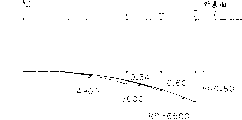
图10是依据本发明第五优选实施方案的具有压力型荫罩格栅的彩色显像管的屏的内外表面的曲率与屏幕边缘部分的楔形量的关系图。Fig. 10 is a graph showing the relationship between the curvature of the inner and outer surfaces of the screen of a color picture tube having a pressure type shadow mask grid and the amount of wedge of the edge portion of the screen according to the fifth preferred embodiment of the present invention.
图11是依据本发明第六优选实施方案的具有压力型荫罩格栅的彩色显像管的屏的内外表面的曲率与屏幕边缘部分的楔形量的关系图。11 is a diagram showing the relationship between the curvature of the inner and outer surfaces of the screen of a color picture tube having a pressure type shadow mask grid and the amount of wedge at the edge of the screen according to the sixth preferred embodiment of the present invention.
图12是依据本发明第七优选实施方案的具有压力型荫罩格栅的彩色显像管的屏的内外表面的曲率与屏幕边缘部分的楔形量的关系图。Fig. 12 is a graph showing the relationship between the curvature of the inner and outer surfaces of the screen of a color picture tube having a pressure type shadow mask grid and the amount of wedge of the edge portion of the screen according to the seventh preferred embodiment of the present invention.
图13是根据本发明第九优选实施方案的具有压力型荫罩格栅的彩色显像管的侧视图及部分剖面图。Fig. 13 is a side view and a partial sectional view of a color picture tube having a pressure type shadow mask grid according to a ninth preferred embodiment of the present invention.
图14是第九优选实施方案的屏的剖面图。Fig. 14 is a sectional view of a panel of a ninth preferred embodiment.
图15是为说明第九优选实施方案的工作过程的屏的部分的剖面图。Fig. 15 is a sectional view of part of the panel for explaining the operation of the ninth preferred embodiment.
图16是说明本发明原理的框图。Figure 16 is a block diagram illustrating the principles of the present invention.
图17是根据本发明第十优选实施方案的具有压力型荫罩格栅的彩色显像管的屏的部分的剖面图。Fig. 17 is a sectional view of part of a screen of a color picture tube having a pressure type shadow mask grid according to a tenth preferred embodiment of the present invention.
图18是依据第十优选实施方案的屏的内外表面的曲率与屏幕边缘部分的楔形量的关系图。Fig. 18 is a graph showing the relationship between the curvature of the inner and outer surfaces of the screen and the amount of wedge of the edge portion of the screen according to the tenth preferred embodiment.
图19是依据第十一优选实施方案的屏的内外表面的曲率与屏幕边缘部分的楔形量的关系图。Fig. 19 is a graph showing the relationship between the curvature of the inner and outer surfaces of the screen and the amount of wedge of the edge portion of the screen according to the eleventh preferred embodiment.
图20是依据本发明第十二优选实施方案的具有压力型荫罩格栅的彩色显像管的屏的部分的剖面图。Fig. 20 is a sectional view of part of a screen of a color picture tube having a pressure type shadow mask grid according to a twelfth preferred embodiment of the present invention.
图21是传统的彩色显像管的侧视图及部分剖面图。Fig. 21 is a side view and a partial sectional view of a conventional color picture tube.
图22是用于传统的彩色显像管中的压力型荫罩格栅的立体图。Fig. 22 is a perspective view of a pressure type shadow mask grid used in a conventional color picture tube.
图23是说明屏幕坐标系的简图。Fig. 23 is a diagram illustrating a screen coordinate system.
图24是传统的平板屏的剖面图。Fig. 24 is a sectional view of a conventional flat screen.
图25是传统的平板屏的特性图。FIG. 25 is a characteristic diagram of a conventional flat screen.
图26是传统的改进屏的剖面图。Fig. 26 is a sectional view of a conventional improved screen.
图27是传统的改进屏的特性图。Fig. 27 is a characteristic diagram of a conventional improved panel.
<A.第一优选实施方案><A. First preferred embodiment>
<A-1.设备结构><A-1. Equipment structure>
将叙述的本发明第一优选实施方案的显像管的对角线尺寸为51cm。图1中所示的第一优选实施方案的显像管与图21中所示的传统的显像管具有相同的结构,除了屏1的形状、偏转线圈6和需时增加的辅助线圈12有所不同之外。图1中,1表示组成彩色显像管外壳的屏,2表示与屏1一起组成彩色显像管(CRT)外壳的漏斗,3表示由按顺序排列在屏的内表面的红、蓝和绿荧光体组成的荧光屏,4表示电子枪,5表示由电子枪4发出的电子束,6表示使电子束5产生电磁偏转的偏转线圈,7表示用作色彩选择电极的压力型荫罩格栅。由于压力型荫罩格栅7的结构在图22中已叙述过了,这里不再赘述。一个方向受应力的荫罩格栅7所具有的特性使它与具有各向同性(所有方向)受应力的障板如具有点状孔栅的障板相比能够提供更好的图像质量。The picture tube of the first preferred embodiment of the present invention which will be described has a diagonal dimension of 51 cm. The kinescope of the first preferred embodiment shown in Fig. 1 has the same structure as the traditional kinescope shown in Fig. 21, except that the shape of the
屏1的外表面在垂直轴方向和水平轴方向都为凸形,其内表面在垂直轴方向为近似线性形,水平轴方向沿Z轴为凸形。偏转线圈6很显然与传统的显像管中的相同,不同的是偏转磁场,特别是垂直线圈产生的磁场。在偏转线圈6靠向电子枪的一边有一个辅助线圈12。在偏转线圈6的近似中间处存在一个虚拟的偏转中心平面13,它与Z轴的交点为偏转中心14。The outer surface of the
图2是放大的本优选实施方案的屏1的主要部分、荧光屏3和压力型荫罩格栅7的剖面图。图的上半部分(Z轴以上的部分)表示垂直轴(V)部分,下半部分(Z轴以下的部分)表示水平轴(H)部分。由图中可清楚地看到,对于屏1的外表面,其垂直轴(V)部分的凸形沿Z轴的曲率半径为ROV,其水平轴(H)部分的凸形沿Z轴的曲率半径为ROH。对于屏的内表面,其垂直轴(V)部分为近似线性形,其水平轴(H)部分的凸形沿Z轴的曲率半径为RIH。Fig. 2 is an enlarged sectional view of the main part of the
当屏1中心点的玻璃厚度为TO时,屏1在垂直轴(X)的终点的玻璃厚度TV为TV=TO-ΔTV。同样地,屏1在水平轴(H)的终点的玻璃厚度TH为TH=TO+ΔTH。参数ΔTV和ΔTV对应的是厚度TO与图23中所叙述的距屏的中心为1v和1h处的厚度之差,以下将称为“楔形”。When the glass thickness at the center point of the
由于荫罩格栅7在垂直轴(V)方向受应力,所以在垂直方向其截面为近似线性形。荫罩格栅7在水平方向的形状形成了一个曲面,该曲面取决于狭缝状孔栅11的间距、屏1内表面的形状和在偏转中心平面13(参照图1)上双边电子束偏离Z轴的偏轴量SB。对于双边电子束,如果G是三色电子束R、G、B的中心,那么双边电子束对应的是R和B。Since the
<A-2.工作过程><A-2. Work process>
为了说明本发明的效果,将参照图4和图5详述当用传统的平行平面平板玻璃屏时所引起的视屏的问题的原因。图4所示的是当观测者19距屏100的外表面95mm处看位于平面屏的内表面上的荧光屏300时,为计算荧光屏300的凸起的情况所设置的屏的模型。这里,观测者19和屏100的外表面之间的距离95mm是假设的最坏的技术估值。在计算的本例中,屏100的外表面不局限为平面,而假设凹形的球面半径,在Z轴上其曲率半径可变。假设其内表面是平面,荧光屏300也同样为平面。这种情况下,屏的垂直轴的终点的边缘厚度为TO+ΔTV,屏的水平轴的终点的边缘厚度为TO+ΔTH。In order to explain the effect of the present invention, the cause of the problem of the viewing screen caused when a conventional parallel plane glass screen is used will be described in detail with reference to FIGS. 4 and 5. FIG. 4 is a screen model set up for calculating the protrusion of the
图5所示是在这种模型下的计算情况。图5中,纵坐标表示视屏的浮起量(mm),横坐标表示观测者看荧光屏300的边缘的角度(。图5中,用曲率半径RP(mm)作为参数,边缘的浮起量用屏幕中心的浮起量归一化。图5中,RP=90000,相当于平面。由计算得到:Figure 5 shows the calculation under this model. Among Fig. 5, ordinate represents the floating amount (mm) of video screen, and abscissa represents the angle (of the edge that the observer sees
(1)即使具有平板屏的屏幕边缘仍上翘。(1) The edge of the screen is still upturned even with a flat screen.
(2)曲率半径越小,边缘的浮起量越大。(2) The smaller the radius of curvature, the larger the floating amount of the edge.
(3)图5中所示的是观测者19与屏之间的距离的函数的特性。(3) Shown in FIG. 5 is the characteristic as a function of the distance between the
(4)负的球半径条件下,浮起量可减小。(4) Under the condition of negative ball radius, the floating amount can be reduced.
虽然这些计算是在假设内表面为平面,外表面为沿Z轴为凹形的条件下进行的,但是若玻璃屏100翻转过来,其在光学上的结果几乎相同。Although these calculations are performed under the assumption that the inner surface is flat and the outer surface is concave along the Z-axis, the optical results are almost the same if the glass screen 100 is turned over.
在第一优选实施方案中,如图2所示,屏1的外表面沿Z轴为凸形,其内表面在垂直轴方向的截面为线性形,水平轴方向的截面为凸形,从而减小了屏幕3边缘的浮起量,使视屏20变得较平。这就是说,它利用了图5中所示的负球面半径作为因素来进行改进。在第一优选实施方案中,屏1的外表面为凸形作为实施方法实现了本发明的目的,或者说减小了视屏20的边缘的浮起量,并且屏1内表面在垂直轴方向为线性形,这便于使用压力型荫罩格栅7。对于水平轴方向的部分,屏沿Z轴形成的凸形与荫罩格栅7的间距、偏转中心平板13处电子束的偏轴量SB及浮起量有关。In the first preferred embodiment, as shown in Figure 2, the outer surface of the
<A-3.特性功能和效果><A-3. Feature functions and effects>
在第一优选实施方案中,如已叙述的,由于外表面沿Z轴为凸形,视屏20可变得较平。例如,与图26中所述的传统的例子相比,其沿垂直轴方向有明显的改善。而且,由于屏的内表面在垂直轴方向(V)为线性形,可以采用传统的使用压力型荫罩格栅的方式。In the first preferred embodiment, as already stated, the
当外表面为图2所示的球面时,在光反射情况下使图像产生不自然的效果。因此,最好在屏的外表面用减小反射的涂层15来消除多余的光反射。When the outer surface is a spherical surface as shown in FIG. 2 , the image will have an unnatural effect in the case of light reflection. Therefore, it is preferable to use a reflection-reducing
已经用垂直轴(V)和水平轴(H)方向的剖面形状来说明了特性。在两个轴之间的空间部分中屏的形状没有特别的限制,例如,它只要是连续平滑的就可以。例如,图3中,垂直轴(V)部分的曲率半径为RV和水平轴(H)部分的曲率半径为RH,如果距垂直轴(V)与中心的夹角为Θ度部分处的曲率半径定义为R,则相交的空间部分的形状可由式(1)得到:The characteristics have been described in terms of the cross-sectional shapes in the vertical axis (V) and horizontal axis (H) directions. The shape of the screen in the space portion between the two axes is not particularly limited, for example, as long as it is continuously smooth. For example, in Fig. 3, the radius of curvature of the vertical axis (V) part is RV and the radius of curvature of the horizontal axis (H) part is RH, if the included angle from the vertical axis (V) and the center is the radius of curvature at the part Defined as R, then the shape of the intersecting space part can be obtained by formula (1):
1/R2=cos2Θ/RV2+sin2Θ/RH2 1/R 2 =cos 2 Θ/RV 2 +sin 2 Θ/RH 2
式(1)适用于内或外表面为非球面的情况。Equation (1) is applicable when the inner or outer surface is aspherical.
<B.第二优选实施方案><B. Second preferred embodiment>
<B-1.设备结构><B-1. Equipment structure>
图6是根据本发明第二优选实施方案的彩色显像管的屏的主要部分的剖面图。除了屏的剖面形状不同外,依据第二优选实施方案的彩色显像管与图1中所示的相同。在第二优选实施方案中,屏1的外表面与图2所示的第一优选实施方案的相同。屏1的内表面在垂直轴(V)方向和水平轴(H)方向都沿Z轴成凸形。Fig. 6 is a sectional view of a main part of a screen of a color picture tube according to a second preferred embodiment of the present invention. The color picture tube according to the second preferred embodiment is the same as that shown in FIG. 1 except that the sectional shape of the screen is different. In the second preferred embodiment, the outer surface of the
<B-2.工作过程><B-2. Work process>
参见图7,当屏为这种形状时,电子束5在双边电子束(参照图1)的偏转中心平面13上偏离Z轴的偏轴量SB的变化量ΔS被用在垂直偏转中。特别地电子束5的垂直偏转的偏轴量在SB和SB+ΔS之间变化。图1中,如果偏转中心14与屏幕3的边缘之间的距离是L,荫罩格栅7和屏1的内表面之间的距离q可由下式式(2)得到:Referring to FIG. 7, when the screen has this shape, the variation ΔS of the off-axis amount SB of the
q=La/3SBq=La/3SB
式(2)适用于高密结构的三色荧光体的荧光屏3。式中,“a”表示荫罩格栅的间距。Formula (2) is applicable to the
为了增大垂直偏转SB以减小q,可以将SB变为SB+ΔS。为将SB变为SB+ΔS,由偏转线圈6的垂直线圈产生的磁场可为近似桶形,或如图1中的虚线所示,在偏转线圈6的后面增加一个辅助线圈12来产生生成S的磁场分量。如图8所示,例如,辅助线圈12绕在硅铁片12a上,产生虚线所示的磁场,该磁场产生图7中所示的分量ΔS。In order to increase the vertical deflection SB to reduce q, SB can be changed to SB+ΔS. In order to change SB into SB+ΔS, the magnetic field generated by the vertical coil of the
<B-3.特性功能和效果><B-3. Feature functions and effects>
该结构是将屏的内表面的垂直方向沿Z轴也成形为凸形。而且,在这种情况下,由于外表面为凸形,屏的内表面沿Z轴成形为凸形就减小了浮起量,这样一来产生的平面视屏20有较理想的效果。水平方向上,其结构与第一优选实施方案相同。第二优选实施方案与第一优选实施方案相比,优点在于其玻璃真空管具有防爆特性。对于光反射来说,最好有减小反射的涂层15。This structure is such that the vertical direction of the inner surface of the panel is also formed into a convex shape along the Z-axis. Also, in this case, since the outer surface is convex, forming the inner surface of the screen convex along the Z axis reduces the amount of lift-off, thus producing a
<C.第三优选实施方案><C. Third preferred embodiment>
图9是根据本发明第三优选实施方案的彩色显像管的屏的主要部分的剖面图。除了屏的剖面形状外,第三优选实施方案与图1所示的相同。在第三优选实施方案中,屏1的外表面沿Z轴成形为对称旋转的凸形。这就减小了由于光反射造成的不自然。这里,最好也使用减小反射的涂层15。屏的内表面形状与第二优选实施方案中的相同。Fig. 9 is a sectional view of a main part of a screen of a color picture tube according to a third preferred embodiment of the present invention. The third preferred embodiment is the same as that shown in FIG. 1 except for the sectional shape of the screen. In a third preferred embodiment, the outer surface of the
<D.第四优选实施方案><D. Fourth preferred embodiment>
屏的内外表面形状的确定应考虑偏转特性ΔS、垂直轴方向和水平轴方向的视屏的平度及视屏的平度。相应地,在这种情况下屏周围的边框的2mm内最好为各向异性的。水平方向的设计只需考虑浮起量。但是,垂直方向的设计,只能利用偏转线圈6或加上辅助线圈12来设计ΔS,这样可以减小边框。这种情况下,ΔSV>ΔSH,使屏的内表面在垂直轴(V)方向为凸形。The determination of the shape of the inner and outer surfaces of the screen should consider the deflection characteristic ΔS, the flatness of the screen in the direction of the vertical axis and the horizontal axis, and the flatness of the screen. Accordingly, in this case the bezel around the screen is preferably anisotropic within 2 mm. The design in the horizontal direction only needs to consider the amount of float. However, for the design in the vertical direction, ΔS can only be designed by using the
<E.第五优选实施方案><E. Fifth preferred embodiment>
<E-1.设备结构><E-1. Equipment structure>
图10是依据本发明第五优选实施方案的彩色显像管的屏的内外表面的曲率与屏幕边缘的楔形量的关系图。表1是对角线尺寸为27cm的彩色显像管在图4和图5情况下的计算结果。Fig. 10 is a diagram showing the relationship between the curvature of the inner and outer surfaces of the screen of the color picture tube according to the fifth preferred embodiment of the present invention and the amount of wedge shape of the edge of the screen. Table 1 is the calculation result of the color picture tube with a diagonal size of 27cm in the case of Fig. 4 and Fig. 5.
表1 16∶9屏幕 Table 1 16:9 screen
A b c RI Ei RO EoA A b c c RI RI Ei RO Eo
D 53° 3.1 133.9 8500 1.05 -13000 0.69D 53° 3.1 133.9 8500 1.05 -13000 0.69
H 48° 2.25 112.7 7000 0.91 -10000 0.64H 48° 2.25 112.7 7000 0.91 -10000 0.64
V 29° 0.80 59.3 无穷 0 -6000 0.29V 29° 0.80 59.3 Infinity 0 -6000 0.29
表1是传统的16∶9的荧光屏3的一个例子,这种情况下,当如图4所示,观测者19距屏100的玻璃中心的距离为95mm时,视屏20的浮起量的估计值的情况可能最差。Table 1 is an example of a conventional 16:9
表1中,D、H和V分别为屏幕的对角线轴、水平轴和垂直轴。符号“a“表示图5中横坐标的角α,其对应各轴的角度分别为53°、48°和29°。符号“b”表示对应于图5中横坐标α的平板屏(RP=90000)的浮起量(mm)。符号“c”表示对应于图23中的距离1h和1v及Z轴到对角线轴终点的距离。例如,屏1的水平轴部分的内表面的曲率半径RI为R7000。相应地,如图5中得知的,在这种情况下,浮起量为4.5mm。为了区分内外表面的曲率半径RP,内表面的曲率半径表示为RI,外表面的曲率半径表示为RO。In Table 1, D, H, and V are the diagonal axis, horizontal axis, and vertical axis of the screen, respectively. The symbol "a" represents the angle α of the abscissa in Fig. 5, and the angles corresponding to the axes are 53°, 48° and 29° respectively. Symbol "b" indicates the floating amount (mm) of the flat screen (RP=90000) corresponding to the abscissa α in FIG. 5 . The symbol "c" indicates the distance corresponding to the distances 1h and 1v in FIG. 23 and the Z axis to the end point of the diagonal axis. For example, the curvature radius RI of the inner surface of the horizontal axis portion of the
<E-2.工作过程><E-2. Work process>
如图4所示的模型中,假设屏100的中心与观测者19的眼睛的位置相距95mm,荧光屏300位于距其13mm的内部为平面的平板13上。如果特性相反,即外表面为平面,R7000的荧光屏沿Z轴(沿观测者19的眼睛的方向)为凸形,如图10所示(如果光学系统也相反),其光学特性几乎相同。相应地,其在水平轴(H)终点处浮起2.25mm。In the model shown in FIG. 4 , it is assumed that the center of the screen 100 is 95 mm away from the position of the eyes of the
由折射率和屏的厚度之间的关系可知,位于平板平面屏上的屏幕中心的浮起量为4.5mm。另一方面,屏的内表面为R7000,则屏幕中心的浮起量为5.2mm。相应地,平板平面屏和内表面为R7000的屏的浮起量的之差ΔΔP为0.7mm。因此,屏的中心与屏的边缘的浮起量相比,水平轴终点处的浮起量为2.25-0.7=1.55mm。这样,屏的中心与屏的边缘的浮起量之差就减小了。From the relationship between the refractive index and the thickness of the screen, it can be known that the floating amount of the center of the screen on the flat screen is 4.5mm. On the other hand, if the inner surface of the screen is R7000, the floating amount of the center of the screen is 5.2mm. Correspondingly, the difference ΔΔP between the floating amount of the flat screen and the screen whose inner surface is R7000 is 0.7mm. Therefore, the floating amount at the end point of the horizontal axis is 2.25-0.7=1.55mm compared with the floating amount of the screen edge compared with the center of the screen. Thus, the difference between the floating amount of the center of the screen and the edge of the screen is reduced.
表1中的ei表示屏的内表面沿Z轴的浮起量,其在水平轴(H)方向为0.91mm。eo表示屏的外表面沿Z轴的浮起量。图10中所示为ei和eo沿各自的轴的浮起量,其中三个轴是重叠地画出的。图10中,横坐标表示距屏的中心的距离,纵坐标表示屏的Z轴,该屏的外表面为凸形,内表面为非球面,即不是球面或柱面,如图中所示。ei in Table 1 represents the floating amount of the inner surface of the panel along the Z axis, which is 0.91 mm in the direction of the horizontal axis (H). eo represents the floating amount of the outer surface of the screen along the Z axis. Shown in Figure 10 are the floats of ei and eo along their respective axes, where the three axes are plotted superimposed. In Fig. 10, the abscissa represents the distance from the center of the screen, and the ordinate represents the Z axis of the screen. The outer surface of the screen is convex, and the inner surface is aspheric, that is, not spherical or cylindrical, as shown in the figure.
表1中,只将屏的外表面成形为凸形就可部分校正平板平面玻璃的浮起量。那么,在这种状态下,屏的边缘部分很薄,对显像管的安全设计来说是不利的。相应地,屏的内表面沿Z轴为凸形产生了楔形。这样,与内表面为平面的情况相比,浮起量减小了ei的值。在本例中,屏的外表面的趋势为:In Table 1, only the outer surface of the screen is formed into a convex shape to partially correct the floating amount of the flat flat glass. Then, in this state, the edge portion of the screen is very thin, which is unfavorable for the safety design of the picture tube. Accordingly, the inner surface of the screen is convex along the Z axis creating a wedge shape. Thus, the floating amount is reduced by the value of ei compared with the case where the inner surface is flat. In this example, the trend of the outer surface of the screen is:
屏的内表面的趋势为:The trend of the inner surface of the screen is:
虽然上述例子所示的是一个27cm显像管的例子,但51cm显像管的内外表面的趋势不变,51cm显像管的曲率半径比本例的曲率半径大。Although the above example shows an example of a 27cm picture tube, the trend of the inner and outer surfaces of the 51cm picture tube remains unchanged, and the radius of curvature of the 51cm picture tube is larger than that of this example.
表1所示为以下几项的极限数字特例:Table 1 shows the extreme number special cases for:
A)由人眼19的位置至屏幕中心的距离(视场)为95mm,这不符合常规,实际中,用于显示的显像管的视场约为300至500mm,这说明,当本例用于实际尺寸时,表1所示的曲率半径的值将增大。A) The distance (field of view) from the position of the
B)在平板平面情况下,为校正边缘的浮起量,当外表面为平面时,得到的屏的内表面的值用来确定内表面沿Z轴的凸形。因此,不必只为了浮起量而增加这些值。B) In the case of a flat panel, to correct the edge lift-off, when the outer surface is flat, the obtained value of the inner surface of the screen is used to determine the convexity of the inner surface along the Z-axis. Therefore, it is not necessary to increase these values just for the amount of float.
<E-3.特性功能和效果><E-3. Feature functions and effects>
上述的结构,不同于图26中所示的传统的模型,虽然使用的荫罩格栅在垂直轴方向的部分为线性形,浮起量可自由调整,这样使显像管的平面性能得到了改善。由于屏的外表面即不是球面也不是平面,所以第五优选实施方案在光反射方面仍存在缺陷。最好在屏的外表面用减小反射的涂层薄膜以减小反射。The above-mentioned structure is different from the traditional model shown in FIG. 26, although the part of the shadow mask grid used in the vertical axis direction is linear, the floating amount can be adjusted freely, so that the planar performance of the picture tube has been improved. The fifth preferred embodiment still suffers from the disadvantage of light reflection since the outer surface of the screen is neither spherical nor planar. Preferably, a reflection-reducing coating film is used on the outer surface of the screen to reduce reflection.
<F.第六优选实施方案><F. Sixth preferred embodiment>
图11所示是第六优选实施方案,在各轴(水平轴、垂直轴和对角线轴)都有些楔形。这样,虽然屏的外表面为凸形,由于屏的外表面的反射使其平面效果不佳,所以其结构沿相应的轴的部分为RO>RI,其中屏的外表面的曲率半径为RO,内表面的曲率半径为RI。而且,更具体地,Figure 11 shows a sixth preferred embodiment, somewhat wedge-shaped in each axis (horizontal, vertical and diagonal). In this way, although the outer surface of the screen is convex, the plane effect is not good due to the reflection of the outer surface of the screen, so the part of the structure along the corresponding axis is RO>RI, wherein the radius of curvature of the outer surface of the screen is RO, The radius of curvature of the inner surface is RI. And, more specifically,
ROV=10,000>RIV=6000ROV=10,000>RIV=6000
ROH=10,000>RIH=7000ROH=10,000>RIH=7000
ROD=13,000>RID=8500ROD=13,000>RID=8500
与图10所示相比,由于特别是在垂直方向的楔形增大了,本优选实施方案在显像管的安全设计方面更优越。Compared with that shown in Fig. 10, the preferred embodiment is superior in terms of safe design of the picture tube due to the enlarged wedge especially in the vertical direction.
<G.第七优选实施方案><G. Seventh preferred embodiment>
图12所示是第七优选实施方案,它是将第六优选实施方案中的屏的外表面成形为沿水平轴为旋转对称的凸形,如图10中所示,最小曲率半径为R6000。在这种情况下,屏的外表面的反射程度与图11中所示的相比有所改进。Figure 12 shows the seventh preferred embodiment, which shapes the outer surface of the screen in the sixth preferred embodiment into a convex shape that is rotationally symmetrical along the horizontal axis, as shown in Figure 10, with a minimum radius of curvature of R6000. In this case, the degree of reflection of the outer surface of the screen is improved compared to that shown in FIG. 11 .
<H.第八优选实施方案><H. Eighth preferred embodiment>
第八优选实施方案是将图10中所示的屏的外表面成形为图12中所示的形状。这种情况下,在牺牲了一些视屏的平面性能的条件下,使屏的外表面的反射程度进一步改善了。当然,在这种情况下,屏的外表面上的减小反射的涂层薄膜补偿了由于屏的外表面为凸形引起的缺陷。An eighth preferred embodiment is to shape the outer surface of the screen shown in FIG. 10 into the shape shown in FIG. 12 . In this case, the reflectivity of the outer surface of the screen is further improved at the expense of some of the planar properties of the screen. In this case, of course, the reflection-reducing coating film on the outer surface of the screen compensates for defects caused by the convex shape of the outer surface of the screen.
<I.第九优选实施方案><I. Ninth preferred embodiment>
<I-1.设备结构><I-1. Device structure>
这里描述的本发明第九优选实施方案的显像管的对角线尺寸为51cm,如图13所示。图13中所示的彩色显像管与图1中描述的第一优选实施方案的显像管的结构几乎相同,相同的部件在图中仍用相同的符号表示,这里不再赘述。The picture tube of the ninth preferred embodiment of the present invention described here has a diagonal dimension of 51 cm, as shown in FIG. 13 . The structure of the color picture tube shown in FIG. 13 is almost the same as that of the picture tube of the first preferred embodiment described in FIG. 1 , and the same components are still represented by the same symbols in the figure, and will not be repeated here.
图13中,屏1A的外表面近似平面,其内表面沿Z轴为非球面非柱面的凸形。In FIG. 13 , the outer surface of the
图14是放大的屏1A的主要部分、荧光屏3A和压力型荫罩格栅7的剖面图。图的上半部分(Z轴以上的部分)表示垂直轴(V)部分,下半部分(Z轴以下的部分)表示水平轴(H)部分。由图14可清楚地得知,屏1A的外表面近似为平面,其内表面在垂直轴(V)和水平轴(H)方向都沿Z轴成凸形。FIG. 14 is an enlarged sectional view of the main part of the
当屏1A中心点的玻璃厚度为TO时,屏1A在垂直轴(V)的终点的玻璃厚度TV为TV=TO+ΔTV。同样地,水平轴(H)的终点的玻璃厚度TH为TH=TO+ΔTH。这里,ΔTV和ΔTV对应的是屏的中心与距屏的中心Z为1v和1h处的厚度之差,如图15中所示,其被称为“楔形”。将它们设置为0<ΔTV<ΔTH。When the glass thickness at the center point of the
由于荫罩格栅7在垂直轴(V)方向受力,其在垂直方向的部分与屏1A的外表面近似平行。在水平方向上,荫罩格栅7的曲面形状取决于狭缝状孔栅11的间距、屏1A内表面的形状和在偏转中心平面13上双边电子束偏离Z轴的偏轴量SB。Since the
<I-2.工作过程><I-2. Work process>
图15是说明上述结构的效果的简图。图中,上半部分表示垂直轴(V)部分,下半部分表示水平轴(H)部分。如所述的,依据第九优选实施方案的屏1A,其外表面近似平面,荧光屏3A位于沿Z轴为凸形的内表面上。这种结构下,例如,当观测者19距屏1A为50cm时,得到的视屏20为近似平面的屏20,如图点划线所示。在屏的外表面使用减小反射的涂层薄膜15。Fig. 15 is a schematic diagram illustrating the effect of the above-mentioned structure. In the figure, the upper half shows the vertical axis (V) part, and the lower half shows the horizontal axis (H) part. As stated, according to the ninth preferred embodiment, the outer surface of the
在传统的平面屏玻璃的情况下,视屏存在的问题的原因在图4中已经叙述过了,这里不再赘述。In the case of the traditional flat screen glass, the reason for the problem of the video screen has been described in FIG. 4 and will not be repeated here.
图16所示为本模型下的计算结果。图16中,纵坐标表示视屏的浮起量(mm),横坐标表示看荧光屏300的边缘的视角(图中,通过使用曲率半径RP(mm)作为参数,将边缘的浮起量相对屏幕中心的浮起量进行归一化。图16中,RP=90000可认为是平面平板的情况。通过计算得到的结论与第一优选实施方案的结论(1)至(4)相同。Figure 16 shows the calculation results under this model. In Fig. 16, the ordinate represents the floating amount (mm) of the video screen, and the abscissa represents the viewing angle of seeing the edge of the fluorescent screen 300 (in the figure, by using the radius of curvature RP (mm) as a parameter, the floating amount of the edge is relative to the center of the screen The amount of float is normalized. Among Fig. 16, RP=90000 can be considered as the situation of plane plate.The conclusion obtained by calculation is the same as the conclusion (1) to (4) of the first preferred embodiment.
<I-3.特性功能和效果><I-3. Feature functions and effects>
第九优选实施方案,如图14所示,屏1A的外表面为平面,其内表面沿Z轴为凸形,这样就减小了浮起量,获得了较平的视屏。而且,其具有的楔形抑制了静态应力的侵害。这就是说,当CRT的内部为真空以防止损坏CRT时,楔形可以减小由大气压施加的持续应力。不必说,当视屏20和屏1A的外表面都为平面时,可以改善平面性能,如图15所示。另一方面,最好没有附加的光反射。因此,最好用减小反射的涂层薄膜15。In the ninth preferred embodiment, as shown in FIG. 14 , the outer surface of the
虽然是以垂直轴(V)部分和水平轴(H)部分来描述其特性的,但是屏的形状在两个轴之间的空间内没有限制,只要它是连续平滑的形状就可以。相应地,交叉部分的形状可以由第一优选实施方案中的式(1)确定。Although its characteristics are described in terms of a vertical axis (V) portion and a horizontal axis (H) portion, the shape of the screen is not limited in the space between the two axes as long as it is a continuous and smooth shape. Accordingly, the shape of the intersection portion can be determined by formula (1) in the first preferred embodiment.
<J.第十优选实施方案><J. Tenth preferred embodiment>
<J-1.设备结构><J-1. Equipment structure>
图18是本发明的第十优选实施方案的彩色显像管的屏的内外表面的曲率与屏幕边缘的楔形量的关系图。第十优选实施方案与第九优选实施方案的情况相同,屏的外表面为平面,屏的内表面沿Z轴为非球面非柱面的凸形,屏幕边缘的玻璃的厚度关系设为TO<TV<TH<TD。TO表示屏的中心的玻璃厚度,TV表示屏幕垂直轴(V)终点处玻璃的厚度,TH表示屏幕水平轴(H)终点处玻璃的厚度,TD表示屏幕对角线轴终点处玻璃的厚度。Fig. 18 is a graph showing the relationship between the curvature of the inner and outer surfaces of the screen of the color picture tube and the wedge amount of the edge of the screen in the tenth preferred embodiment of the present invention. The tenth preferred embodiment is the same as the ninth preferred embodiment, the outer surface of the screen is a plane, the inner surface of the screen is aspheric and non-cylindrical convex along the Z axis, and the thickness relationship of the glass at the edge of the screen is set as T < TV<TH<TD. TO represents the glass thickness at the center of the screen, TV represents the thickness of the glass at the end of the vertical axis (V) of the screen, TH represents the thickness of the glass at the end of the horizontal axis (H) of the screen, and TD represents the thickness of the glass at the end of the diagonal axis of the screen.
表2 4∶3屏幕Table 2 4:3 screen
A B c RP EA A B C c RP E
D 45° 2.0 101.7 6500 0.80
H 37° 1.2 77.5 5000 0.60H 37° 1.2 77.5 5000 0.60
V 29° 0.75 57.3 4900 0.34V 29° 0.75 57.3 4900 0.34
表2所示的是对角线尺寸为20cm并满足上述玻璃厚度的条件的彩色显像管,经图16得到的计算结果。Table 2 shows the color picture tube whose diagonal size is 20cm and meets the above conditions of glass thickness, and the calculation results obtained through Fig. 16 .
本例对应的是视屏的浮起量的估计值为最坏的情况,即荧光屏3的高度和宽度比为3∶4,观测者19距屏幕玻璃中心的距离为95mm,如图4所示。This example corresponds to the worst case in which the estimated value of the floating amount of the screen is the worst, that is, the height to width ratio of the
<J-2.工作过程><J-2. Work process>
表2中,D、H和V分别对应的是屏的对角线轴、水平轴和垂直轴。符号“a”表示图16中所示的横坐标角(,其对应各轴的角度分别为53°、48°和29°。符号“b”表示的是在平行平板平面屏(RP=90000)的条件下,对应于图16中的横坐标(的浮起量(mm)。符号“c”表示对应于图23中的距离1h和1v及Z轴到对角线轴终点的距离。对于RP来说,例如,当RP为R5000并且(=37时,由图16可知,在这种情况下,水平轴部分的浮起量为2.4mm。In Table 2, D, H, and V correspond to the diagonal axis, horizontal axis, and vertical axis of the screen, respectively. The symbol "a" represents the abscissa angle shown in Figure 16 (, the angles corresponding to each axis are 53°, 48° and 29° respectively. The symbol "b" represents the flat screen (RP=90000) Under the conditions, corresponding to the abscissa in Figure 16 (the floating amount (mm). The symbol "c" represents the distance corresponding to the distance 1h and 1v in Figure 23 and the distance from the Z axis to the end point of the diagonal axis. For RP Say, for example, when RP is R5000 and (=37, it can be seen from FIG. 16 that in this case, the floating amount of the horizontal axis portion is 2.4 mm.
在图4所示的模型中,假设屏100的中心距观测者19的眼睛为95mm,荧光屏300位于距屏100 13mm处的内部为平面(平行平板)的平板上。在特性相反的情况下,即外表面为平面,R5000的荧光屏沿Z轴(沿观测者19的眼睛的方向)为凸形,如图17所示,这就是说,当光学系统反转时,其光学特性几乎相同。在水平轴方向屏的边缘处,或在图23中的1h处,视屏位于内部2.4mm处。这里,由于水平轴方向屏的边缘位置是屏的内表面的中心减去0.6mm处的位置,视屏的浮起量为+1.8mm。另一方面,在屏的中心处,由于其内表面为R5000时得到的浮起量的差ΔΔP的结果约为1.0mm,最后的浮起量约为0.8mm。与利用传统的平行平板得到的1.2mm的浮起量相比,中心部分与边缘部分的差就减小了。In the model shown in FIG. 4 , it is assumed that the center of the screen 100 is 95 mm away from the eyes of the
<J-3.特性功能和效果><J-3. Feature functions and effects>
这使视屏沿各个轴为近似平面成为可能。表2中的e表示与平面板相比,视屏浮起的情况,其在水平轴(H)方向为0.6mm。图18所示在各个轴上,e的值,三个轴画成互相重叠的。图18中,横坐标表示距屏幕中心的距离,纵坐标表示屏的Z轴坐标,该屏的外表面为平面,内表面为非球面,其沿相应的轴的剖面部分为即非球面也非柱面,如图中所示。即使荧光屏的尺寸增大,其曲率半径比所示的这些都大的情况下,这一趋势仍不变。This makes it possible for the viewing screen to be approximately flat along each axis. e in Table 2 indicates the case where the viewing screen is raised compared to the flat panel, which is 0.6 mm in the direction of the horizontal axis (H). Figure 18 shows the value of e on each axis, the three axes are drawn overlapping each other. In Fig. 18, the abscissa indicates the distance from the center of the screen, and the ordinate indicates the Z-axis coordinate of the screen. The outer surface of the screen is a plane, and the inner surface is an aspheric surface, and the section along the corresponding axis is either aspherical or non-spherical. cylinder, as shown in the figure. This tendency remains the same even when the size of the phosphor screen is increased and its radius of curvature is larger than those shown.
<K.第十一优选实施方案><K. Eleventh preferred embodiment>
图19是依据第十一优选实施方案的彩色显像管的屏的内外表面的曲率与屏幕边缘的楔形量的关系图。表3所示是具有16∶9荧光屏的27cm宽屏显像管的计算结果,这里屏的玻璃厚度设为TO<TV<TH<TD,与第十优选实施方案中的相同。Fig. 19 is a graph showing the relationship between the curvature of the inner and outer surfaces of the screen of the color picture tube according to the eleventh preferred embodiment and the amount of wedge of the edge of the screen. Table 3 shows the calculation results for a 27 cm wide-screen picture tube with a 16:9 fluorescent screen, where the glass thickness of the screen is set as TO<TV<TH<TD, the same as in the tenth preferred embodiment.
表3 16∶8屏幕Table 3 16:8 screen
A b c RP EA A b b c c RP E
D 53° 3.1 133.9 8500 1.05D 53° 3.1 133.9 8500 1.05
H 48° 2.25 112.7 7000 0.91H 48° 2.25 112.7 7000 0.91
V 29° 0.80 59.3 4400 0.40V 29° 0.80 59.3 4400 0.40
<L.第十二优选实施方案><L. Twelfth preferred embodiment>
<L-1.设备结构><L-1. Equipment structure>
下面将参照图7、图8和图20来叙述第十二优选实施方案。第十二优选实施方案中,双边电子束在偏转中心平面13(参见图13)上的偏离Z轴的偏轴量SB经偏转线圈后其垂直偏转的增加确保了楔形的量。为此,利用了偏转线圈的垂直线圈或图13中的辅助线圈12的磁场特性。在辅助线圈12中,如图8所示,辅助线圈12绕在硅铁片12a上,产生虚线所示的磁场。A twelfth preferred embodiment will be described below with reference to FIGS. 7 , 8 and 20 . In the twelfth preferred embodiment, the off-axis amount SB of the bilateral electron beams on the deflection center plane 13 (see FIG. 13 ) deviates from the Z axis, and the increase in the vertical deflection after passing through the deflection yoke ensures the amount of wedge. For this, the magnetic field properties of the vertical coil of the deflection yoke or of the
<L-2.工作过程><L-2. Work process>
当偏转中心14至荧光屏3的边缘的距离为L时,如图14所示,荫罩格栅7和屏1A的内表面之间的距离q可由第二优选实施方案中的式(2)表示。在垂直方向,为获得楔形ΔTV(来增大SB,减小q),上式中的SB变为SB+ΔS,这样SB的值增大了。When the distance from the
为得到分量ΔS,由偏转线圈6的垂直线圈在一个方向上产生的磁场比传统方法和水平方向更近似桶形,其最终使垂直方向上的屏的玻璃产生楔形。另一产生ΔS的方法是,产生ΔS的磁场的发生电流流经辅助线圈12。To obtain the component ΔS, the magnetic field generated by the vertical coils of the
图20是第十二优选实施方案的屏1A的剖面图。如图20所示,屏1A的外表面为平面,其内表面沿Z轴为凸形。而且,对于屏的中心厚度为TO的情况,垂直方向的楔形量ΔTV和水平方向的楔形量ΔTH不同,例如,为ΔTV<ΔTH。具体地说,可将它们设为ΔTV=1.5mm和ΔTH=2.0mm。Fig. 20 is a sectional view of a
<L-3.特性功能和效果><L-3. Feature functions and effects>
水平方向的设计只需考虑ΔTH的浮起量。对于垂直方向的ΔTV,荫罩格栅7和屏1的内表面之间的距离q对于电子束R、G和B的排列关系来说很是重要的。本例中,由于荫罩格栅7在一个方向受力,由偏转线圈6的垂直线圈产生的磁场在一个方向近似为桶形,辅助线圈12位于偏转线圈6靠近电子枪的一边,如图13中虚线表示,增大了SB,减小了q,从而确保了ΔTV。这使垂直方向也为足够的楔形。The design in the horizontal direction only needs to consider the floating amount of ΔTH. For ΔTV in the vertical direction, the distance q between the
我们已经详细介绍了本发明,前面的叙述在所有方面是说明性的,并且没有任何限制。在不脱离本发明的范围的情况下,可以有许多的变化和革新。Having described the invention in detail, the foregoing description is illustrative in all respects and not restrictive in any way. Many changes and innovations are possible without departing from the scope of the present invention.
Claims (15)
Applications Claiming Priority (9)
| Application Number | Priority Date | Filing Date | Title |
|---|---|---|---|
| JP23686697A JP3282553B2 (en) | 1997-09-02 | 1997-09-02 | Color picture tube device equipped with an extended shadow grill |
| JP23686797 | 1997-09-02 | ||
| JP236866/1997 | 1997-09-02 | ||
| JP236867/1997 | 1997-09-02 | ||
| JP236867/97 | 1997-09-02 | ||
| JP236866/97 | 1997-09-02 | ||
| JP313644/1997 | 1997-11-14 | ||
| JP313644/97 | 1997-11-14 | ||
| JP31364497A JP3497360B2 (en) | 1997-09-02 | 1997-11-14 | Color picture tube device equipped with an extended shadow grill |
Publications (2)
| Publication Number | Publication Date |
|---|---|
| CN1211808A CN1211808A (en) | 1999-03-24 |
| CN1149621C true CN1149621C (en) | 2004-05-12 |
Family
ID=27332411
Family Applications (1)
| Application Number | Title | Priority Date | Filing Date |
|---|---|---|---|
| CNB981168825A Expired - Fee Related CN1149621C (en) | 1997-09-02 | 1998-08-04 | Color picture tube device with pressure type shadow mask grid |
Country Status (6)
| Country | Link |
|---|---|
| US (1) | US6133681A (en) |
| EP (1) | EP0901145B1 (en) |
| KR (1) | KR100288030B1 (en) |
| CN (1) | CN1149621C (en) |
| DE (1) | DE69813973T2 (en) |
| TW (1) | TW393661B (en) |
Families Citing this family (11)
| Publication number | Priority date | Publication date | Assignee | Title |
|---|---|---|---|---|
| KR100267963B1 (en) * | 1998-08-17 | 2000-10-16 | 구자홍 | Cathode ray panel |
| KR100432114B1 (en) * | 1999-04-28 | 2004-05-17 | 가부시키가이샤 히타치세이사쿠쇼 | Color cathode-ray tube |
| US6337535B1 (en) * | 1999-10-26 | 2002-01-08 | Lg Electronics Inc. | Panel in cathode ray tube |
| KR100402738B1 (en) | 2000-02-29 | 2003-10-22 | 삼성에스디아이 주식회사 | Panel of cathode ray tube |
| KR100331820B1 (en) * | 2000-04-12 | 2002-04-09 | 구자홍 | Flat Cathode Ray Tube |
| JP2002160246A (en) * | 2000-11-22 | 2002-06-04 | Seibu:Kk | Mold with clamp and press molding method using the same |
| KR100408005B1 (en) * | 2002-01-03 | 2003-12-03 | 엘지.필립스디스플레이(주) | Panel for CRT of mask stretching type |
| DE10322151B4 (en) * | 2002-05-17 | 2009-07-02 | Samsung Corning Precision Glass Co., Ltd., Gumi | Flat screen with improved implosion protection for use in a cathode ray tube |
| KR20060035151A (en) * | 2004-10-21 | 2006-04-26 | 엘지.필립스 디스플레이 주식회사 | Cathode ray tube |
| KR100712905B1 (en) * | 2004-11-03 | 2007-05-02 | 엘지.필립스 디스플레이 주식회사 | Cathode ray tube |
| US20070126332A1 (en) * | 2005-12-02 | 2007-06-07 | Matsushita Toshiba Picture Display Co., Ltd. | Color picture tube |
Family Cites Families (14)
| Publication number | Priority date | Publication date | Assignee | Title |
|---|---|---|---|---|
| US4537322B1 (en) * | 1982-12-13 | 1998-03-10 | Tokyo Shibaura Electric Co | Glass envelope for a cathode-ray tube |
| US4570101A (en) * | 1983-09-06 | 1986-02-11 | Rca Corporation | Cathode-ray tube having a faceplate panel with a smooth aspherical screen surface |
| JPH0644457B2 (en) * | 1986-01-30 | 1994-06-08 | 松下電子工業株式会社 | Color picture tube |
| FR2634945B1 (en) * | 1988-07-27 | 1996-04-26 | Videocolor | METHOD FOR MANUFACTURING A HIGH DEFINITION COLOR TELEVISION TUBE AND HIGH DEFINITION TRICHROME TELEVISION TUBE |
| JP2845908B2 (en) * | 1988-11-30 | 1999-01-13 | 株式会社日立製作所 | Shadow mask type color cathode ray tube |
| NL9000111A (en) * | 1990-01-17 | 1991-08-16 | Philips Nv | CATHODE JET TUBE WITH CURVED IMAGE WINDOW AND COLOR IMAGE DISPLAY. |
| NL9000325A (en) * | 1990-02-12 | 1991-09-02 | Koninkl Philips Electronics Nv | CATHODE JET TUBE AND IMAGE DISPLAY DEVICE. |
| IT1239510B (en) * | 1990-03-30 | 1993-11-03 | Videocolor Spa | CATHODE TUBE HAVING A PERFECTED FRONT SHEET, WITH 16/9 "WIDTH / HEIGHT RATIO |
| JPH0636710A (en) * | 1992-07-21 | 1994-02-10 | Hitachi Ltd | Display control circuit and device |
| JP3337784B2 (en) * | 1993-10-22 | 2002-10-21 | 株式会社東芝 | Color picture tube |
| JP2636706B2 (en) * | 1993-11-16 | 1997-07-30 | 旭硝子株式会社 | Glass bulb for cathode ray tube |
| JPH09245685A (en) * | 1996-03-06 | 1997-09-19 | Toshiba Corp | Color picture tube |
| JP3271565B2 (en) * | 1997-02-24 | 2002-04-02 | 三菱電機株式会社 | Color cathode ray tube panel |
| JPH1173896A (en) * | 1997-08-28 | 1999-03-16 | Mitsubishi Electric Corp | Color picture tube |
-
1998
- 1998-05-22 TW TW087108003A patent/TW393661B/en not_active IP Right Cessation
- 1998-06-04 US US09/090,085 patent/US6133681A/en not_active Expired - Fee Related
- 1998-06-11 DE DE69813973T patent/DE69813973T2/en not_active Expired - Fee Related
- 1998-06-11 EP EP98304640A patent/EP0901145B1/en not_active Expired - Lifetime
- 1998-07-20 KR KR1019980029071A patent/KR100288030B1/en not_active IP Right Cessation
- 1998-08-04 CN CNB981168825A patent/CN1149621C/en not_active Expired - Fee Related
Also Published As
| Publication number | Publication date |
|---|---|
| EP0901145A3 (en) | 1999-03-17 |
| EP0901145A2 (en) | 1999-03-10 |
| KR19990029257A (en) | 1999-04-26 |
| US6133681A (en) | 2000-10-17 |
| TW393661B (en) | 2000-06-11 |
| CN1211808A (en) | 1999-03-24 |
| KR100288030B1 (en) | 2001-06-01 |
| EP0901145B1 (en) | 2003-05-02 |
| DE69813973D1 (en) | 2003-06-05 |
| DE69813973T2 (en) | 2004-03-11 |
Similar Documents
| Publication | Publication Date | Title |
|---|---|---|
| CN1153250C (en) | Panel of a color cathode ray tube | |
| CN1134815C (en) | Cathode rays tube device | |
| CN1149621C (en) | Color picture tube device with pressure type shadow mask grid | |
| CN1124636C (en) | Cathode ray tube and method for mfg. the same | |
| CN1277286C (en) | Cathode-ray tube | |
| CN1210754C (en) | Color CRT | |
| CN1147916C (en) | Display panel for CRT | |
| CN1144255C (en) | Cathode ray tube | |
| CN1183572C (en) | Cathode-ray tube | |
| CN1252787C (en) | Color CRT using electrostatic quadrupole lens to apply reduced dynamic focused voltage | |
| CN1156880C (en) | Colour cathode ray tube | |
| CN1094845A (en) | cathode ray tube | |
| CN1171274C (en) | color cathode ray tube | |
| JPH11144648A (en) | Color picture tube device with stretched shadow grille | |
| JP3513175B2 (en) | Display device | |
| CN1278362C (en) | Color picture tube | |
| CN1225765C (en) | Color cathode ray tube | |
| CN1739062A (en) | Surface reflection type metallic screen and method of manufacturing the same | |
| CN1822300A (en) | cathode ray tube | |
| JP2001126632A (en) | Color picture tube | |
| CN1251288C (en) | Color cathode ray tube | |
| CN1388560A (en) | Colour cathode-ray tube with improved colour purity | |
| EP1336982A2 (en) | Color cathode ray tube | |
| CN1409352A (en) | Color picture tube with improved horizontal resolution | |
| JP2006504237A (en) | Display device having flat display panel |
Legal Events
| Date | Code | Title | Description |
|---|---|---|---|
| C10 | Entry into substantive examination | ||
| SE01 | Entry into force of request for substantive examination | ||
| C06 | Publication | ||
| PB01 | Publication | ||
| C14 | Grant of patent or utility model | ||
| GR01 | Patent grant | ||
| C17 | Cessation of patent right | ||
| CF01 | Termination of patent right due to non-payment of annual fee |
Granted publication date: 20040512 Termination date: 20100804 |