CN1409352A - Color picture tube with improved horizontal resolution - Google Patents
Color picture tube with improved horizontal resolution Download PDFInfo
- Publication number
- CN1409352A CN1409352A CN02144087A CN02144087A CN1409352A CN 1409352 A CN1409352 A CN 1409352A CN 02144087 A CN02144087 A CN 02144087A CN 02144087 A CN02144087 A CN 02144087A CN 1409352 A CN1409352 A CN 1409352A
- Authority
- CN
- China
- Prior art keywords
- lens
- deflection
- magnetic
- horizontal
- magnetic field
- Prior art date
- Legal status (The legal status is an assumption and is not a legal conclusion. Google has not performed a legal analysis and makes no representation as to the accuracy of the status listed.)
- Pending
Links
Images


Classifications
-
- H—ELECTRICITY
- H01—ELECTRIC ELEMENTS
- H01J—ELECTRIC DISCHARGE TUBES OR DISCHARGE LAMPS
- H01J29/00—Details of cathode-ray tubes or of electron-beam tubes of the types covered by group H01J31/00
- H01J29/46—Arrangements of electrodes and associated parts for generating or controlling the ray or beam, e.g. electron-optical arrangement
- H01J29/48—Electron guns
- H01J29/51—Arrangements for controlling convergence of a plurality of beams by means of electric field only
-
- H—ELECTRICITY
- H01—ELECTRIC ELEMENTS
- H01J—ELECTRIC DISCHARGE TUBES OR DISCHARGE LAMPS
- H01J29/00—Details of cathode-ray tubes or of electron-beam tubes of the types covered by group H01J31/00
- H01J29/46—Arrangements of electrodes and associated parts for generating or controlling the ray or beam, e.g. electron-optical arrangement
- H01J29/70—Arrangements for deflecting ray or beam
- H01J29/701—Systems for correcting deviation or convergence of a plurality of beams by means of magnetic fields at least
- H01J29/702—Convergence correction arrangements therefor
Abstract
A color picture tube device that can suppress the deformation of the electron beam spot shape and improve the horizontal resolution using a simple construction is provided. A horizontal deflection coil generates a horizontal deflection magnetic field that is substantially uniform. A plurality of electron beams are substantially parallel with the tube axis when passing one end of a core of a deflection yoke facing an electron gun. A lens forming unit forms a lens through which the plurality of electron beams pass, between the electron gun end of the core and a phosphor screen. The lens has an effect of causing the plurality of electron beams to approach each other in a horizontal direction, irrespective of which part of the phosphor screen the plurality of electron beams reach.
Description
Technical field
The present invention relates to many electron beams of a kind of deflection from electron gun with a plurality of in-line negative electrodes (in-linecathode), and on phosphor screen the color picture tube of color display.
Background technology
In having the color picture tube of in line gun, the negative electrode of blue (B) three looks of corresponding red (R) green (G) is by horizontal aligument in this in line gun, and three electron beams that electron gun sends need can be in a suitable point (this is called as " assembling converge ") on phosphor screen.From (self) convergence and dynamic convergence is to be widely used in the common technology that produces this convergence.
The auto-convergence technology produces convergence by the lack of balance magnetic deflection field that generates deflection beam.Usually, horizontal deflection magnetic field is distorted into pincushion and barrel-shaped respectively with vertical deflection magnetic field.In this way, each of three electron beams different amount of deflection all when passing magnetic deflection field is so that three electron beams are assembled on whole phosphor screen.
The dynamic convergence technology produces convergence by producing the magnetic field (dynamic convergence magnetic field) that is used for dynamically changing two outer electron-beam angles before with three electrons beam deflecting.The intensity in magnetic field changes according to the amount of deflection, so that three electron beams are assembled on whole phosphor screen.
The auto-convergence color picture tube has a defective: at approaching fluoroscopic edge, the spot shape of three electron beams deforms.The distortion of this spot shape causes resolution to descend.Propose various technology and solved this problem (for example: disclose unexamined patent application No.H09-102288).Yet these effort adapt to the current trend of improving video data density and strengthening deflection angle for the thin type TV unsatisfactorily.
Dynamically-and assemble color picture tube to use undistorted balanced magnetic field as magnetic deflection field, do not produce the decline of resolution yet.But this type needs complicated structure.
Summary of the invention
The purpose of this invention is to provide a kind of color picture tube simple in structure, this picture tube can suppress the beam spot warpage and improve horizontal resolution.
The color picture tube that generates coloured image by many electron beams of a deflection and on phosphor screen has reached described purpose, and this color picture tube comprises: have a plurality of in-line negative electrodes and launch the electron gun of many electron beams; The deflection yoke (yoke) that comprises horizontal deflection coil, frame deflector coil and magnetic core, this horizontal deflection coil produces the horizontal deflection magnetic field of basis equalization, and this frame deflector coil produces vertical deflection magnetic field; The lens that can form the lens that many electron beams pass through form the unit, these lens are being faced between magnetic core one end and phosphor screen of electron gun, wherein when by magnetic core plane during to an end of electron gun, many electron beam is basic parallel with the tubular axis of color picture tube, lens have: (a) a kind of horizontal convergence effect, make no matter how the bar electron beam reaches fluoroscopic which part, all convergence each other in the horizontal direction; And (b) intensity distributions, it is far away more apart from the phosphor screen vertical center line to arrive fluoroscopic parts horizontal direction at many electron beams, and the horizontal convergence effect is weak more.
According to this structure, with the magnetic field of basis equalization as horizontal deflection magnetic field.The result can suppress the beam spot warpage by the generation of distortion magnetic deflection field, can improve horizontal resolution with this.In addition, the position of electron beam scioptics is along with electron beam is changed by horizontal deflection, and the lens strength of having adjusted horizontal direction distributes, and comes to produce on whole phosphor screen and assembles.So basically do not need to use the high frequency horizontal yoke current to adjust and assemble used magnetic field intensity.Therefore color picture tube can be realized with simple circuit structure.
Should point out that this used speech " convergence " not only comprises the situation that many electron beams are assembled fully, and comprise that many electron beams are not exclusively assembled but near each other, especially the situation on the phosphor screen edge.
The accompanying drawing summary
The detailed description of carrying out from the accompanying drawing below in conjunction with the expression specific embodiment of the invention will make these and other objects of the present invention, and advantage and feature are more obvious.
Fig. 1 is the end view of the color picture tube of embodiment of the present invention;
Fig. 2 is the perspective view of the example structure of deflection yoke in the embodiment;
Fig. 3 is the sectional view by the first half of a deflection yoke that comprises tubular axis and cut perpendicular to the plane of horizontal direction (X-direction);
Fig. 4 represents the route of the electron beam of three horizontal aliguments seeing from vertical direction;
Fig. 5 represents the structure and the effect of the magnetic lens that formed by quadrupole coil shown in Figure 2;
Fig. 6 is when not carrying out vertical deflection, the example of the magnetic flux of quadripolar magnetic field shown in Figure 5 (flux) density;
Fig. 7 represents deflection angle θ and the relation of assembling power F;
Fig. 8 represents the relation of deflection angle θ and magnetic flux density By;
Fig. 9 represents a kind of quadripolar magnetic field, and wherein each magnetic pole (north and south poles) is approximately 45 ° for the angle [alpha] of Y-axis;
Figure 10 has represented the distribution of magnetic flux density on X-axis of quadripolar magnetic field shown in Figure 9;
Figure 11 has illustrated how the angle [alpha] of each magnetic pole is provided with in the quadripolar magnetic field of embodiment;
Figure 12 represents the placement of magnet etc. in the embodiment;
Figure 13 represents to use the example of electrostatic lens; With
Figure 14 is illustrated in the magnetic field that produces between the two poles of the earth of the magnetic field that produces between the two poles of the earth of upper coil shown in Figure 2 and lower coil.
Specific embodiments
Embodiment to color picture tube of the present invention is described with reference to the accompanying drawings.
(total of color picture tube)
Fig. 1 is the end view of the color picture tube of embodiment of the present invention.
This color picture tube roughly is made up of a kind of encapsulation that comprises panel 10, glass awl (funnel) 20, in line gun 30 and deflection yoke 100.Phosphor screen forms at the inner surface of panel 10.In line gun 30 is at the neck of glass awl 20, to three electron beams of phosphor screen emission.Deflection yoke 100 is installed near the glass awl 20.In this embodiment, with three horizontal aliguments of emission and substantially along the electron gun of X-axis electron beam parallel to each other as electron gun 30, so that three electron beams enter horizontal deflection magnetic field substantially parallel to each other.Although this embodiment is described is to see from phosphor screen one side three electron beams from left to right put in order to be B, G, and the situation of R, the present invention is not limited to this order.
Deflection yoke 100 forms magnetic deflection field, the electron beam that comes deflection to launch from electron gun 30 in glass awl 20.Fig. 2 is the perspective view of the example of expression deflection yoke 100 structures.Fig. 3 is the sectional view by the first half of a deflection yoke that comprises tubular axis (Z axle) and cut perpendicular to the plane of horizontal direction (X-direction).Comprise horizontal deflection coil 110 successively, insulation frame 120, frame deflector coil 130, ferrite core 140 at outward direction (from the inside of glass awl 20 to the outside) deflection yoke 100.
Horizontal deflection coil 110 is made by lead being around in horizontal coil 110a and the 110b that saddleback forms by a pair of. Horizontal coil 110a and 110b are set the window 111a and the 111b that are positioned at the middle part are separately faced one another, and place, so that closely contact with insulation frame 120 along the inner surface of insulation frame 120.Equally, frame deflector coil 130 is made by lead being around in the formed vertical coil of saddleback by a pair of.The ferrite core 140 that provides is used to surround these vertical coil.Ferrite core 140 is as the magnetic core of the magnetic deflection field that is produced by horizontal deflection coil 110 and frame deflector coil 130.
In this embodiment, the coil that is used to form lens (by the magnetic lens of quadripolar magnetic field formation) provides in each window 111a and 111b.Below the coil that will provide in window 111a is called coil 151, and the coil that provides in window 111b is called lower coil 152.Also will go up coil 151 and lower coil 152 is generically and collectively referred to as quadrupole coil 150.Last coil 151 and lower coil 152 form magnetic lens, and this magnetic lens makes three electron beams assemble in the fluoroscopic horizontal direction that places panel 10 inner surfaces.Can introduce the function of quadrupole coil 150 below in detail.
Explain deflection yoke 100 each position component with reference to Fig. 3.Among the figure, be reference point (Z=0) on tubular axis (Z axle) with the set positions of the phosphor screen end of quadrupole coil 150 (upper coil 151 among Fig. 3), its positive direction is in phosphor screen one side, and negative direction is in electron gun one side.Like this, horizontal deflection coil 110 is positioned at-50 to 23 (millimeters), and frame deflector coil 130 is positioned at-50 to 10, and ferrite core 140 is positioned at-45 to 4.Simultaneously, the magnetic core of quadrupole coil 150 is positioned at-26 to 0.Point out that the magnetic core wide of quadrupole coil 150 is 15 millimeters here, the window 111a (111b) that is embedded in the insulation frame 120 goes up (though explanation figure 2 illustrates coil 151 and lower coil 152 for convenience).
A kind of horizontal sawtooth deflection current of corresponding horizontal deflection frequency is offered horizontal deflection coil 110.Magnetic field of vertical direction generation that the result is a horizontal deflection coil 110 in glass awl 20, and intrinsic deflection electron beam in the horizontal direction.Simultaneously, the vertical sawtooth deflection current with a kind of corresponding vertical deflection frequency offers frame deflector coil 130.Frame deflector coil 130 produces a magnetic field in the horizontal direction of glass awl 20 as a result, and at the vertical direction deflection beam.
In this embodiment, the horizontal deflection magnetic field that produces by horizontal deflection coil 110 is a kind of balanced magnetic field basically.Use the method, can prevent that near the beam spot shape the phosphor screen horizontal edge from deforming.To the notion in the basis equalization magnetic field of this embodiment be made an explanation below.
The horizontal deflection magnetic field of basis equalization is as follows.
Suppose that the Z axle is a tubular axis, X-direction is fluoroscopic horizontal direction, and Y direction is fluoroscopic vertical direction, and mark the Building X on the Z axle and the Building Y mark is 0.(x z) represents the magnetic flux density of the Y direction component of horizontal deflection magnetic field with Bh.So Bh (x, z) can represent by formula 1:
Bh (x, z)=Bh
0(z)+Bh
2(z) x
2... (formula 1)
Wherein x is illustrated in the interior offset variable apart from the Z axle of X-direction, and z represents Building Z target variable.
In the formula 1, Bh
0(z) be the magnetic flux density of the Y direction component of horizontal deflection magnetic field on the Z axle, and be the function of z.Bh
2(z) being known as the secondary distortion factor, also is the function of z.Bh
2(z) serve as X
2Coefficient.If no matter z value how, Bh
2O'clock (z)=0, Bh (x, z) then by the decision of z value, and no matter x value how.In this case, horizontal deflection magnetic field is balanced fully magnetic field.
Yet, realize that by coil design so balanced fully magnetic field is very difficult.Balanced fully magnetic field, in fact a Bh have been realized even do certain trial
2(z) finally will have some components, although be slight.Therefore in this embodiment, if horizontal deflection magnetic field satisfies formula 2 at least in 75% scope of horizontal deflection coil 110 length of Z-direction, this horizontal deflection magnetic field just is considered to basis equalization magnetic field.Here, with magnetic flux distribution Bh on the Z axle
0(z) maximum normalization is 1, and x represents with millimeter.
-1 * 10
-4≤ Bh
2(z)≤1 * 10
-4(1/mm
2) ... (formula 2)
On the other hand, vertical deflection magnetic field needs the vertical effect according to the lens of three electron beams of horizontal convergence on phosphor screen, just at the lens effect of vertical direction mobile electron bundle, adjusts.
If lens do not have vertical effect, the vertical deflection magnetic field of frame deflector coil 130 need be designed to the magnetic field of basis equalization, assemble so that when the electron beam vertical deflection, produce.Suppose that the Z axle is a tubular axis, X-direction is fluoroscopic horizontal direction, and Y direction is fluoroscopic vertical direction, and mark the Building X on the Z axle and the Building Y mark is 0.With Bv (y, z) magnetic flux density of the X-direction component of expression vertical deflection magnetic field.So Bv (y, z) available formula 3 expressions:
Bv (y, z)=Bv
0(z)+Bv
2(z) y
2... (formula 3)
Wherein y is illustrated on the Y direction apart from the variable of Z axial displacement, and z represents the variable of Z coordinate.
In the formula 3, Bv
0(z) be the magnetic flux density of the X-direction component of vertical deflection magnetic field on the Z axle, and be the function of z.Bv
2(z) being called the secondary distortion factor, also is the function of z.Bv
2(z) serve as y
2Coefficient.If no matter z value how, Bv
2O'clock (z)=0, Bv (y, z) then by the decision of z value, and no matter y value how.In this case, vertical deflection magnetic field is a balanced fully magnetic field.
Yet, realized balanced fully magnetic field, in fact a Bv even do certain trial
2(z) finally will have some components, as the situation of horizontal deflection magnetic field.From here, if vertical deflection magnetic field satisfies formula 4 at least in 75% scope of frame deflector coil 130 length of Z-direction, this vertical deflection magnetic field is considered to basis equalization magnetic field.Here, with magnetic flux distribution Bv on the Z axle
0(z) maximum normalization is 1, and y represents with millimeter.
-1 * 10
-4≤ Bv
2(z)≤1 * 10
-4(1/mm
2) ... (formula 4)
If lens have the vertical divergence effect, promptly a kind of effect that electron beam is removed from the center of vertical direction, the amount difference of vertically removing of every electron beam.Therefore, the vertical deflection magnetic field of frame deflector coil 130 need be designed to barrel field, eliminate this vertical divergence effect.Therefore, when the electron beam vertical deflection, may produce convergence.In the formula 3,, then be considered to barrel field if vertical deflection magnetic field satisfies formula 5:
Bv
2(z)<-1 * 10
-4(1/mm
2) ... (formula 5)
On the other hand, if lens have the vertical convergence effect, promptly a kind of effect that electron beam is moved to the center of vertical direction, the amount difference of the vertical moving of every electron beam.Therefore, the vertical deflection magnetic field of frame deflector coil 130 need be designed to the pincushion field, eliminate this vertical convergence effect.Therefore, may produce convergence during the electron beam vertical deflection.In the formula 3,, then be considered to the pincushion field if vertical deflection magnetic field satisfies formula 6:
Bv
2(z)>1 * 10
-4(1/mm
2) ... (formula 6)
In this embodiment, quadrupole coil 150 forms magnetic quadrupole lens.This lens have horizontal convergence effect and vertical divergence effect.Therefore, vertical deflection magnetic field is designed to barrel field.Secondary distortion factor Bv
2(z) be maximum value near the peak value in magnetic field, its maximum value is set as Bv
2(z)=-16 * 10
-4(1/mm
2).
Equally, during the electron gun end of the ferrite core 140 in entering deflection yoke 100, these three electron beams are parallel to each other substantially.Substantially parallel with what given a definition and mentioned here.Fig. 4 represents the route of the electron beam of three horizontal aliguments seeing from vertical direction.Here do not show magnetic quadrupole lens.Among the figure, S represents the horizontal interval of adjacent electron beam 80 on the main lens 60 of electron gun 30.L represents 60 distances to phosphor screen 70 along tube axial direction from main lens.φ is illustrated in the electron gun end of ferrite core 140, every axle angulation that outer electron-beam is parallel with concentricity electron beam (or tubular axis).Therefore, if three electron beams satisfy formula 7, then be considered to substantially parallel mutually:
| φ |<(1/2) tan
-1(S/L) ... (formula 7)
Suppose that phosphor screen is measured as 86cm from the upper left corner to the lower right corner, then deflection angle be to the maximum 100 ° (about S=6mm, L=450mm).If | φ |<0.38 °, electron beam is parallel to each other substantially.Actual design can be carried out according to following method.At first set | φ |=0 °, set other design parameter then.If depart from, can do trickle adjustment, finally satisfy | φ |<0.38 °.
Therefore, horizontal deflection magnetic field is designed to basis equalization magnetic field, three electron beams that enter the magnetic deflection field scope are aligned to parallel to each other substantially.Although the result arrives fluoroscopic three electron beams to exist in the horizontal direction and depart from mutually, do not exist mutually in vertical direction and depart from.Therefore, can make three electron-beam convergences if adjust offset.In this embodiment, the magnetic quadrupole lens that is formed by quadrupole coil 150 is used to make three electron-beam convergences in the horizontal direction.Although this lens have the vertical divergence effect, as mentioned above, can eliminate this effect by vertical deflection magnetic field being formed barrel field.
Following specific explanations is by the effect of the magnetic quadrupole lens of quadrupole coil 150 formation.Fig. 5 has represented upper coil 151, lower coil 152 and between pass through three electron beams (R, G, B), from phosphor screen one side as can be seen.In this embodiment, by forming upper coil 151 and lower coil 152 respectively on the central part that lead 40 is made around the Ni ferrite.Lead 40 is provided the electric current of a stable state.Although upper coil 151 and lower coil 152 each have 100 circles in this embodiment, the number of turns of each coil can be adjusted arbitrarily.
Use this structure, upper coil 151 and lower coil 152 play magnet coil, are formed on the magnetic pole at two ends.The result generates quadripolar magnetic field as shown in Figure 5.Here to point out only to have represented among Fig. 5 the vertical component of quadripolar magnetic field.In more detail, magnetic field 1511 have from arctic of upper coil 151 to the vertical component in the South Pole of lower coil 152.Magnetic field 1521 has from the arctic of lower coil 152 and to the South Pole of upper coil 151 vertical component is arranged.Magnetic field 1511 and 1521 pairs of electron beams apply an external force in the horizontal direction.
The vertical component of this quadripolar magnetic field has a kind of magnetic flux distribution for the horizontal direction position shown in Figure 6.Here, By represents the magnetic flux density of the vertical component of quadripolar magnetic field, and X is illustrated in the displacement of horizontal direction from tubular axis.The peak value 1515 and 1525 of magnetic flux density absolute value appears near the magnetic pole of magnetic field 1511 and 1521.Article three, electron beam is all the time between these two peak values 1515 and 1525.Along with electron beam by horizontal deflection, the position of three electron beams between two peak values 1515 and 1525 changes.
In this embodiment, three electron beams are parallel to each other substantially when entering the magnetic deflection field scope.Therefore,, just can make two outer electron-beams to the other side's bending, make three electron beams converge at the phosphor screen center like a cork by the horizontal convergence effect of using quadripolar magnetic field if three electron beams are not carried out horizontal deflection by horizontal deflection magnetic field.Yet Anywhere horizontal direction on phosphor screen is assembled if three electron beams, only provide just not enough so that three electron beams of quadripolar magnetic field by horizontal deflection.
Make the design principle of the quadripolar magnetic field that three electron beams assemble in this embodiment of explained later on whole phosphor screen.
Along with electron beam upper deflecting bigger (for example deflection angle θ increase) in the horizontal direction, the distance between the phosphor screen (supposing that the horizontal convergence lens are positioned at deflection center) of the horizontal convergence lens that quadripolar magnetic field forms and electron beam arrival will increase.Phosphor screen is flat more, and this trend is just obvious more.Therefore, when deflection angle θ increased, the horizontal convergence lens were used to make two outer electron-beams need reduce to the convergence power F of the other side's bending.From here, check produces the requirement of assembling when supposing electron beam not by vertical deflection below.
Assemble power F and also do not change during even suppose by horizontal deflection at three electron beams.Therefore, three crossing points of electron beam approximately are positioned on the circuit orbit.Use θ
0The deflection angle of expression center electron beam, Lm represent that center electron beam passes through the distance between the joining of the point of deflection center and three electron beams, L
0Point and not during executive level deflection the distance joining of three electron beams between of expression center electron beam by deflection center.Be Lm and L below
0Between have an approximation relation:
Lm L
0Cos θ
0... (formula 8)
On the other hand, when three electron beams intersect on phosphor screen, center electron beam by deflection center point and the distance L m ' between the joining of three electron beams for L
0Following approximation relation is arranged:
Lm ' L
0/ cos θ
0... (formula 9)
In this embodiment, horizontal deflection magnetic field is balanced magnetic field basically, and three electron beams that enter horizontal deflection magnetic field are parallel to each other substantially.This factor is represented each deflection angle approximately equal of deflection angle and two outer electron-beams of center electron beam.Therefore, the deflection angle of every electron beam can be represented as θ.Therefore, utilize the ratio of Lm and Lm ' can determine to reduce great convergence power F.That is to say that assembling power F need have following approximation relation with deflection angle θ:
F=Lm/Lm '=cos
2θ ... (formula 10)
Here, when electron beam during not by horizontal deflection, deflection angle is made as 0; When electron beam by to the positive direction deflection of trunnion axis (X-axis) time, deflection angle is made as+θ; When electron beam by to the negative direction deflection of trunnion axis the time, deflection angle is made as-θ.Formula 10 can be expressed as the curve of Fig. 7.
Assemble power F in order to change according to deflection angle θ in this way, will there be following relation in the magnetic flux density By of the quadripolar magnetic field on the X-axis with deflection angle θ.This is to obtain from the result that formula 10 is quadratured.
By=B
0{ θ+(1/2) sin2 θ } ... (formula 11)
Here, B
0It is a proportionality constant.If the X-axis positive direction shown in Fig. 2,6, B
0<0.Then, formula 11 can be expressed as the curve chart of Fig. 8.Among the figure, trunnion axis is represented deflection angle θ.Yet, if magnetic quadrupole lens is positioned near the deflection center, even when trunnion axis is represented X, also can adopt similar distribution.Therefore, even three electron beams by horizontal deflection, pass between two peak values 1515 and 1525 of the magnetic flux density of Fig. 6 example distribution by making three electron beams, three electron beams also can suitably be assembled.
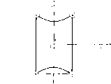
Fig. 9 represents a kind of typical quadripolar magnetic field, and each magnetic pole (north and south poles) of this quadripolar magnetic field is 45 ° for the angle of Y-axis.The magnetic flux distribution of this quadripolar magnetic field on X-axis can be expressed as straight line shown in Figure 10.In this embodiment, horizontal deflection magnetic field is basis equalization magnetic field, and three electron beams are substantially parallel when entering horizontal deflection magnetic field.Therefore, if the quadripolar magnetic field that uses to shown in Figure 9 similar, then three electron beams are difficult to suitably convergences by horizontal deflection the time.
On the other hand, the quadripolar magnetic field in this embodiment has following structure.The first, the angle [alpha] of each magnetic pole (seeing Figure 11) is set in the following scope:
10 °<α<35 ° ... (formula 12)
By like this, magnetic flux distribution is distorted the alphabetical S shape shown in Fig. 6,8.For magnetic flux distribution more is similar to shown in Fig. 6,8, preferably uses rod magnet or the coil on the shaft-like magnetic core and it is installed, so that near the magnetic flux the magnetic pole (is seen Figure 12) in the horizontal direction.Other method of adjusting the magnetic flux orientation can replace the rod scheme.
By on the ferrite core 140 of deflection yoke 100 around a loop coil, also can form quadripolar magnetic field.Equally in this case, by the magnetic pole angle being set and adjusting magnetic core shape, the ratio of circle, the ratio of the magnitude of current etc., the magnetic flux that can control each magnetic pole flows out.Therefore, when the coil that does not use this embodiment to describe, also can obtain same effect.
The design principle of quadripolar magnetic field has been described above.In actual design, preferably optimize more specifically.Equally, top example has used the approximation of formula 8.Yet,, just can use for example approximation of formula 8 ' if horizontal deflection magnetic field has the length of the Z-direction in the embodiment like this.Therefore, assembling power F is not limited to top described.
Lm L
0Cos
2θ
0... (formula 8 ')
When using the approximation of formula 8 ', assemble power F and magnetic flux distribution By and use formula 10 ' and 11 ' expression respectively:
F=Lm/Lm '=cos
3θ ... (formula 10 ')
By=B
0' { (3/4) sin θ+(1/12) sin3 θ } ... (formula 11 ')
Although there is not figure to release, their curve chart and formula 10 with 11 similar.Therefore this situation also can produce convergence.Equally, even quadripolar magnetic field and deflection center are placed on diverse location, this also can handle by the relation of a following example.Represent the distance of quadripolar magnetic field and deflection center with d, θ represents deflection angle.Displacement in the quadripolar magnetic field that is caused by the θ angular deflection is d * tan θ so.
Above-described magnetic flux distribution (see figure 6) has following effect.At three electron beams not by the fluoroscopic horizontal center of horizontal deflection (center electron beam for example shown in Figure 5 (G) is at the X-axis mid point), the X=0 in the center electron beam corresponding diagram 6, and be not subjected to the influence of quadripolar magnetic field.Simultaneously, two outer electron-beams (B and R) are acted on by the power that the vertical component with rightabout and same intensity by quadripolar magnetic field moves forward center electron beam.The result of this horizontal convergence effect is three electron-beam convergences.The magnetic lens that forms by quadripolar magnetic field applies this horizontal convergence effect.
On the other hand, when three electron beams during by the horizontal deflection magnetic field horizontal deflection, the horizontal convergence effect will be put on three electron beams as described above.Because quadripolar magnetic field is nearer than the electron gun end of horizontal deflection magnetic field apart from phosphor screen, the position of three electron beams in this quadripolar magnetic field will change according to amount of deflection yet in this case.So intensity differences of three suffered quadripolar magnetic field influences of electron beam.Here, do not compared by the situation of horizontal deflection with three electron beams, it is more weak to act on three horizontal convergence effects on the electron beam.Specifically, the convergent effect of magnetic lens in quadripolar magnetic field therefrom the peripheral along continuous straight runs of mind-set weaken.In other words, the intensity distributions that magnetic lens has makes that distance center is far away more in the horizontal direction, and convergent effect is weak more.When three electron beam deflections in the horizontal direction are big more, the convergent effect of the quadripolar magnetic field part that they pass through is weak more.Therefore three electron beams peripheral suffered convergent effect in the horizontal direction is than a little less than the center.
Utilize this structure, three electron beams can be able to be converged at the farther point in the ratio center at phosphor screen edge.Therefore, in color picture tube, the distance between electron gun and the phosphor screen is big at the phosphor screen center at phosphor screen horizontal edge ratio, so can produce suitable convergence at fluoroscopic horizontal edge.This can realize by the intensity distributions of magnetic lens.Therefore, needn't synchronously change the convergent effect of magnetic lens with horizontal deflection.Certainly change convergent effect, make it synchronous with horizontal deflection.Yet, because horizontal deflection frequency is very high, problem such as may cause that for example consumed power is more and circuit load is bigger.Yet, can use a kind of simple structure to produce convergence, and need not synchronously change convergent effect with horizontal deflection according to the present invention.
As above-described, use simple structure can improve resolution with following four features.
(a) magnetic field with basis equalization is used as horizontal deflection magnetic field.
(b) three electron beams are parallel to each other along tubular axis substantially when entering the magnetic deflection field scope.
(c) between the electron gun end of the ferrite core of deflection yoke and phosphor screen, generate a magnetic lens that three electron beams is applied the horizontal convergence effect.
(d) eliminate the vertical effect of any unwanted magnetic lens by the Distribution of Magnetic Field of vertical deflection magnetic field.
Make in this way,, can on whole phosphor screen, realize easily assembling no matter the point of electron beam aiming is at fluoroscopic horizontal center or at horizontal edge.
When electron beam during,, preferably adopt according to the horizontal convergence effect of the strength reduction magnetic lens of vertical deflection magnetic field or the structure of vertical divergence effect if can not fully adjust convergence by vertical deflection.For example: the effect that can synchronously change magnetic lens with vertical deflection.Because the vertical deflection frequency is low to moderate approximately several ten Hz, synchronously change the horizontal convergence effect or the vertical divergence effect of magnetic lens so with vertical deflection, will can not cause higher power consumption and more complicated circuit structure.Equally, can revise magnetic lens so that the intensity distributions that has makes at the vertical direction distance center far more, the horizontal convergence effect is weak more.
Modification
Invention has been described by above-mentioned embodiment, but clearly the invention is not restricted to above-mentioned embodiment.The example of revising is as follows.
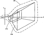
(1) above-mentioned embodiment has been described the quadripolar magnetic field that coil is formed and has been used as the situation of lens, but the invention is not restricted to this situation.For example, as long as have suitable intensity distributions and horizontal convergence effect, can use electrostatic lens.Figure 13 has represented to use the example of this electrostatic lens.Among the figure, the shield member that provides in glass awl 20 is separated in the shielding 171 of electron gun one side with in the shielding 172 of phosphor screen one side, and they have different current potentials.Gap between it provides electrostatic lens.Here preferably select concrete structure, for example level of current potential when considering other condition, and the shape of parts.Perhaps can be used in combination electrostatic lens and magnetic lens.In this case, electrostatic lens can carry out meticulous adjustment to the convergence that magnetic lens produces.
(2) above-mentioned embodiment has been described the situation that generates quadripolar magnetic field with coil.Yet,, can use magnet to generate quadripolar magnetic field if do not need synchronously to adjust magnetic field intensity with vertical deflection.In this situation, need to use magnet with the low-temperature coefficient that shows good temperature characteristics.Also can be by lead be around on the magnet, and carry out trickle adjustment and form coil.
(3) above-mentioned embodiment has been described in the electron beam above and below provides two coils to generate the situation of quadripolar magnetic field, but the invention is not restricted to this.For example, can and right-handly provide two coils, four coils perhaps are provided at the diagonal angle of electron beam at the left of electron beam.Equally, can use sextupole magnetic field or magnetic field, the ends of the earth to replace quadripolar magnetic field.In any situation, magnetic pole should be placed to and can generate the external force that three electron beams are assembled in the horizontal direction.In addition as mentioned above, preferably control the outflow of magnetic flux.
(4) as mentioned above, magnetic quadrupole lens has the vertical divergence effect.Basically can eliminate or reduce this vertical deflection effect by the Distribution of Magnetic Field of using vertical deflection magnetic field.Another program is the increase along with the vertical deflection amount, can weaken the intensity of lens self.The use also capable of being combined of these two kinds of methods.Yet more accurate if desired convergence solves following problem about the vertical effect of lens with regard to needs.
Figure 14 has represented to be formed at the magnetic field 1512 between the two poles of the earth of upper coil 151 and has been formed at magnetic field 1522 between the two poles of the earth of lower coil 152.When using magnetic quadrupole lens, these magnetic fields 1512 and 1522 have a kind of vertical divergence effect that makes three electron beam offset from perpendicular centers.Only use the Distribution of Magnetic Field of vertical deflection magnetic field can't eliminate this lens effect.The 1512 pairs of electron beams in magnetic field have a kind of effect that makes progress, and the 1522 pairs of electron beams in magnetic field have a kind of downward effect.In addition, the intensity of this effect is for each electron beam difference.This can cause to assemble and lose efficacy.Therefore, in the time can not ignoring the effect of magnetic field 1512 and 1522, can provide a kind of mechanism and vertical deflection synchronously to eliminate or reduce magnetic field 1512 and 1522.
(5) above-mentioned embodiment has been described three situations that electron beam is parallel to each other substantially of electron gun 30 emissions, but the invention is not restricted to this.For example can use two of a kind of emissions electron gun of the outer beam of direction inwardly.In this case, behind three electron beams of electron gun emission, can use a kind of simple magnetic field generation equipment to revise the route of electron beam, for example use the convergence yoke (magnetic field of mentioning is different from magnetic deflection field) of extensive use to make electron beam parallel to each other substantially here.
(6) above-mentioned embodiment has been provided by the situation that provides quadrupole coil 150 to form magnetic lens by in deflection yoke 100, but magnetic lens can be provided at the zone different with magnetic deflection field.For example, magnetic lens can be provided between phosphor screen and the deflection yoke 100.
(7) above-mentioned embodiment is described the situation of using lens.Yet, if provide a plurality of this lens just can increase design freedom at tube axial direction.Particularly when at least one lens shaped is formed in deflection yoke magnetic core and at least one residue lens shaped and is formed between the magnetic core of deflection yoke and the phosphor screen, can regulate respectively and assemble and panel (raster) distorts.This makes can carry out two kinds of adjustings arbitrarily.
Although described the present invention fully by the example with reference to accompanying drawing, should be understood that different variations and revising all is tangible for a person skilled in the art.
Therefore, these variations and modification all comprise within the scope of the present invention.
Claims (20)
1. many electron beams of a deflection and produce the color picture tube of coloured image on phosphor screen comprise:
A kind of electron gun that has a plurality of in-line negative electrodes and launch many electron beams;
A kind of deflection yoke that comprises horizontal deflection coil, frame deflector coil and magnetic core, horizontal deflection coil generates the horizontal deflection magnetic field of basis equalization, and frame deflector coil generates vertical deflection magnetic field; With
A kind of lens that form the lens that many electron beams pass through form the unit, and these lens are in the face of between magnetic core one end and phosphor screen of electron gun,
Wherein these many electron beams are when magnetic core one end by facing gun, and are basic parallel with the tubular axis of color picture tube,
Lens have: (a) a kind of horizontal convergence effect, it is all near each other in the horizontal direction no matter arrive fluoroscopic which parts to cause many electron beams, (b) a kind of intensity distributions, the fluorescence component that these many electron beams arrive is far away more with phosphor screen vertical centre linear distance in the horizontal direction, and the horizontal convergence effect is weak more.
2. color picture tube as claimed in claim 1,
Wherein when fluorescence component that these many electron beams arrive on the phosphor screen horizontal center line or near the time, these lens have a kind of horizontal convergence effect, and many electron beams are assembled on phosphor screen.
3. color picture tube as claimed in claim 1,
Wherein when this many electron beams during not by any horizontal deflection magnetic field and vertical deflection magnetic field deflection, these lens have a kind of horizontal convergence effect, make many electron beams convergence each other in the horizontal direction.
4. color picture tube as claimed in claim 1,
Wherein, when this many electron beams during by the horizontal deflection magnetic field horizontal deflection, the position of these many electron beam scioptics changes in the horizontal direction.
5. color picture tube as claimed in claim 1,
Wherein these lens are magnetic lens.
6. color picture tube as claimed in claim 5,
The intensity of wherein horizontal convergence effect can be adjusted by the magnetic flux distribution of magnetic lens.
7. color picture tube as claimed in claim 5,
Wherein the first type surface of magnetic lens is positioned near the deflecting coil of horizontal deflection magnetic field.
8. color picture tube as claimed in claim 5,
Wherein this magnetic lens is four utmost points (quadrupole) magnetic lens.
9. color picture tube as claimed in claim 5,
Wherein this lens formation unit pack contains magnet, at least one magnetic part in magnet coil and its two combination.
10. color picture tube as claimed in claim 9,
Wherein this lens form unit pack and contain two magnetic parts, by two magnetic parts are placed to make each magnetic part south face to the arctic of another magnetic part, magnetic quadrupole lens is formed this magnetic lens.
11. as the color picture tube of claim 10,
Wherein these two magnetic parts are positioned the above and below in the zone that these many electron beams pass through respectively.
12. as the color picture tube of claim 11,
Wherein when many electron beams during not by any horizontal deflection magnetic field and vertical deflection magnetic field deflection, four utmost points of magnetic quadrupole lens be positioned at its center corresponding to four summits of the rectangle of center electron beam by point and
The angle [alpha] that is formed by first straight line and second straight line satisfies 10 °<α<35 °, and first straight line connects the central point on the upper and lower limit of the center of rectangle and rectangle, and second straight line connects the center of rectangle and any summit of rectangle.
13. color picture tube as claimed in claim 9,
Wherein at least one magnetic part is embedded in the insulation frame between horizontal deflection coil and frame deflector coil.
14. color picture tube as claimed in claim 5,
Wherein by on magnetic core around coil form this magnetic lens.
15. color picture tube as claimed in claim 5,
Wherein vertical deflection magnetic field is shaped as barrel-shaped.
16. color picture tube as claimed in claim 1,
Wherein when many electron beams during not by any horizontal deflection magnetic field and vertical deflection magnetic field deflection, the horizontal convergence effect is the strongest.
17. as the color picture tube of claim 16,
Wherein along with many electron beams are many more by the vertical deflection magnetic field vertical deflection, the horizontal convergence effect is weak more.
18. as the color picture tube of claim 17,
Wherein use vertical yoke current to adjust the horizontal convergence effect.
19. color picture tube as claimed in claim 1,
Wherein these lens comprise electrostatic lens.
20. as the color picture tube of claim 19,
Wherein these lens are towards between fluoroscopic magnetic core one end and the phosphor screen.
Applications Claiming Priority (4)
| Application Number | Priority Date | Filing Date | Title |
|---|---|---|---|
| JP305531/2001 | 2001-10-01 | ||
| JP2001305531 | 2001-10-01 | ||
| JP2002019683 | 2002-01-29 | ||
| JP19683/2002 | 2002-01-29 |
Publications (1)
| Publication Number | Publication Date |
|---|---|
| CN1409352A true CN1409352A (en) | 2003-04-09 |
Family
ID=26623548
Family Applications (1)
| Application Number | Title | Priority Date | Filing Date |
|---|---|---|---|
| CN02144087A Pending CN1409352A (en) | 2001-10-01 | 2002-09-30 | Color picture tube with improved horizontal resolution |
Country Status (4)
| Country | Link |
|---|---|
| US (1) | US6861793B2 (en) |
| EP (1) | EP1306877A3 (en) |
| KR (1) | KR20030028429A (en) |
| CN (1) | CN1409352A (en) |
Families Citing this family (3)
| Publication number | Priority date | Publication date | Assignee | Title |
|---|---|---|---|---|
| US6924590B2 (en) * | 2002-02-21 | 2005-08-02 | Matsushita Electric Industrial Co., Ltd. | Color picture tube device with distortion correction coils |
| US20060043867A1 (en) * | 2004-09-01 | 2006-03-02 | Matsushita Toshiba Picture Display Co., Ltd. | Color picture tube apparatus |
| US7485859B2 (en) * | 2007-04-17 | 2009-02-03 | International Business Machines Corporation | Charged beam apparatus and method that provide charged beam aerial dimensional map |
Family Cites Families (18)
| Publication number | Priority date | Publication date | Assignee | Title |
|---|---|---|---|---|
| US3430099A (en) * | 1966-08-23 | 1969-02-25 | Gen Electric | Simplified deflection system for plural in-line beam cathode ray tube |
| JPS6029183B2 (en) | 1976-08-25 | 1985-07-09 | 株式会社日立製作所 | deflection yoke |
| US4231009A (en) * | 1978-08-30 | 1980-10-28 | Rca Corporation | Deflection yoke with a magnet for reducing sensitivity of convergence to yoke position |
| US4433268A (en) * | 1980-08-19 | 1984-02-21 | Tokyo Shibaura Denki Kabushiki Kaisha | Deflection yoke for a color cathode ray tube |
| JPS5830046A (en) | 1981-08-14 | 1983-02-22 | Nec Corp | In-line type color cathode ray tube |
| JPS6286648A (en) | 1985-10-11 | 1987-04-21 | Toshiba Corp | Color picture tube |
| US4988926A (en) * | 1989-02-08 | 1991-01-29 | U.S. Philips Corporation | Color cathode ray tube system with reduced spot growth |
| EP0421523B1 (en) * | 1989-10-02 | 1995-06-28 | Koninklijke Philips Electronics N.V. | Colour display tube system with reduced spot growth |
| DE69212873T2 (en) * | 1991-04-02 | 1997-03-06 | Philips Electronics Nv | Color picture tube with reduced spot growth |
| JPH0521016A (en) | 1991-07-12 | 1993-01-29 | Toshiba Corp | Color picture tube |
| DE69311298T2 (en) | 1993-02-18 | 1997-10-09 | Thomson Tubes & Displays | Deflection yoke with a pair of magnets near its minor axis |
| US5905331A (en) * | 1994-01-13 | 1999-05-18 | Hitachi, Ltd. | Cathode ray tube with deflection aberration correcting electrode |
| JPH08212939A (en) * | 1995-02-08 | 1996-08-20 | Mitsubishi Electric Corp | Crt and its resolution improving device |
| US5777429A (en) * | 1996-02-22 | 1998-07-07 | Sony Corporation | Device for correction of negative differential coma error in cathode ray tubes |
| TW417132B (en) * | 1996-02-27 | 2001-01-01 | Hitachi Ltd | CRT, deflection-defocusing correcting member therefor, a method of manufacturing same member, and an image display system including same CRT |
| JP2001043815A (en) | 1998-12-16 | 2001-02-16 | Toshiba Corp | Color cathode ray tube device |
| US6534935B1 (en) | 1999-10-21 | 2003-03-18 | Matsushita Electric Industrial Co., Ltd. | Color CRT apparatus |
| JP2002093354A (en) | 1999-10-21 | 2002-03-29 | Matsushita Electric Ind Co Ltd | Color crt device |
-
2002
- 2002-09-30 EP EP02256787A patent/EP1306877A3/en not_active Withdrawn
- 2002-09-30 US US10/260,162 patent/US6861793B2/en not_active Expired - Fee Related
- 2002-09-30 CN CN02144087A patent/CN1409352A/en active Pending
- 2002-10-01 KR KR1020020059687A patent/KR20030028429A/en not_active Application Discontinuation
Also Published As
| Publication number | Publication date |
|---|---|
| EP1306877A2 (en) | 2003-05-02 |
| US6861793B2 (en) | 2005-03-01 |
| EP1306877A3 (en) | 2003-12-03 |
| US20030080670A1 (en) | 2003-05-01 |
| KR20030028429A (en) | 2003-04-08 |
Similar Documents
| Publication | Publication Date | Title |
|---|---|---|
| CN1107967C (en) | Small-neck-diameter colour cathode-ray tube | |
| CN1061463C (en) | Electron gun and cathode-ray tube | |
| CN1140108C (en) | Misconvergence and gemetric distortion correction apparatus for deflection yoke | |
| CN1409352A (en) | Color picture tube with improved horizontal resolution | |
| CN1050442C (en) | Deflection system with controlled beam spot | |
| CN1058103C (en) | Color cathode ray tube having improved focus | |
| CN1232285A (en) | Color cathode ray tube with reduced dynamic focus voltage for electrostatic quadrupole lens thereof | |
| CN1216854A (en) | Color teletude device | |
| CN1173380C (en) | Saturated reactor | |
| CN1084927C (en) | Electronic gun for color cathode ray tube | |
| CN1266274A (en) | CRT device | |
| CN1264245A (en) | Colour cathode-ray tube with cross convergence detuning correction device | |
| CN1087487C (en) | Color cathode ray tube | |
| CN1255845C (en) | Deflection system | |
| CN1171273C (en) | Colour picture tube | |
| CN1197112C (en) | Cathode ray tube device | |
| CN1201367C (en) | Color cathode-ray tube apparatus | |
| CN1165948C (en) | Cathode ray tube equipment | |
| WO2002078038A2 (en) | Color cathode ray tube apparatus | |
| CN1267958C (en) | Electron gun of cathode ray tube | |
| CN1227708C (en) | Coloured cathode ray tube equipment | |
| CN1308365A (en) | Color CRT with convergence corrector | |
| CN1215220A (en) | Cathode ray tube | |
| CN1744266A (en) | Color picture tube apparatus | |
| CN1700398A (en) | Color cathode ray tube apparatus |
Legal Events
| Date | Code | Title | Description |
|---|---|---|---|
| C06 | Publication | ||
| PB01 | Publication | ||
| C10 | Entry into substantive examination | ||
| SE01 | Entry into force of request for substantive examination | ||
| AD01 | Patent right deemed abandoned | ||
| C20 | Patent right or utility model deemed to be abandoned or is abandoned |