CN114921932A - Base and clothes treatment equipment - Google Patents
Base and clothes treatment equipment Download PDFInfo
- Publication number
- CN114921932A CN114921932A CN202210540760.6A CN202210540760A CN114921932A CN 114921932 A CN114921932 A CN 114921932A CN 202210540760 A CN202210540760 A CN 202210540760A CN 114921932 A CN114921932 A CN 114921932A
- Authority
- CN
- China
- Prior art keywords
- dust
- cleaning
- air
- base
- dust collection
- Prior art date
- Legal status (The legal status is an assumption and is not a legal conclusion. Google has not performed a legal analysis and makes no representation as to the accuracy of the status listed.)
- Pending
Links
- 239000000428 dust Substances 0.000 claims abstract description 267
- 238000004140 cleaning Methods 0.000 claims abstract description 205
- 238000013519 translation Methods 0.000 claims description 3
- NJPPVKZQTLUDBO-UHFFFAOYSA-N novaluron Chemical compound C1=C(Cl)C(OC(F)(F)C(OC(F)(F)F)F)=CC=C1NC(=O)NC(=O)C1=C(F)C=CC=C1F NJPPVKZQTLUDBO-UHFFFAOYSA-N 0.000 abstract description 7
- 238000009423 ventilation Methods 0.000 description 37
- 238000001035 drying Methods 0.000 description 29
- 238000000034 method Methods 0.000 description 9
- 238000012546 transfer Methods 0.000 description 6
- 230000009286 beneficial effect Effects 0.000 description 5
- 238000010438 heat treatment Methods 0.000 description 5
- 238000004891 communication Methods 0.000 description 3
- 230000000694 effects Effects 0.000 description 3
- 210000001503 joint Anatomy 0.000 description 3
- 238000007789 sealing Methods 0.000 description 3
- 239000010865 sewage Substances 0.000 description 3
- 238000005406 washing Methods 0.000 description 3
- 239000006185 dispersion Substances 0.000 description 2
- 230000002349 favourable effect Effects 0.000 description 2
- 238000001914 filtration Methods 0.000 description 2
- 230000005484 gravity Effects 0.000 description 2
- 238000010521 absorption reaction Methods 0.000 description 1
- 238000009825 accumulation Methods 0.000 description 1
- 238000007605 air drying Methods 0.000 description 1
- 238000013459 approach Methods 0.000 description 1
- 238000010586 diagram Methods 0.000 description 1
- 238000007599 discharging Methods 0.000 description 1
- 238000005516 engineering process Methods 0.000 description 1
- 238000001704 evaporation Methods 0.000 description 1
- 230000008020 evaporation Effects 0.000 description 1
- 239000012535 impurity Substances 0.000 description 1
- 230000002035 prolonged effect Effects 0.000 description 1
- 238000002791 soaking Methods 0.000 description 1
- 230000001954 sterilising effect Effects 0.000 description 1
- 238000010408 sweeping Methods 0.000 description 1
- XLYOFNOQVPJJNP-UHFFFAOYSA-N water Substances O XLYOFNOQVPJJNP-UHFFFAOYSA-N 0.000 description 1
Images


Classifications
-
- D—TEXTILES; PAPER
- D06—TREATMENT OF TEXTILES OR THE LIKE; LAUNDERING; FLEXIBLE MATERIALS NOT OTHERWISE PROVIDED FOR
- D06F—LAUNDERING, DRYING, IRONING, PRESSING OR FOLDING TEXTILE ARTICLES
- D06F39/00—Details of washing machines not specific to a single type of machines covered by groups D06F9/00 - D06F27/00
- D06F39/001—Arrangements for transporting, moving, or setting washing machines; Protective arrangements for use during transport
-
- A—HUMAN NECESSITIES
- A47—FURNITURE; DOMESTIC ARTICLES OR APPLIANCES; COFFEE MILLS; SPICE MILLS; SUCTION CLEANERS IN GENERAL
- A47L—DOMESTIC WASHING OR CLEANING; SUCTION CLEANERS IN GENERAL
- A47L11/00—Machines for cleaning floors, carpets, furniture, walls, or wall coverings
- A47L11/24—Floor-sweeping machines, motor-driven
-
- A—HUMAN NECESSITIES
- A47—FURNITURE; DOMESTIC ARTICLES OR APPLIANCES; COFFEE MILLS; SPICE MILLS; SUCTION CLEANERS IN GENERAL
- A47L—DOMESTIC WASHING OR CLEANING; SUCTION CLEANERS IN GENERAL
- A47L11/00—Machines for cleaning floors, carpets, furniture, walls, or wall coverings
- A47L11/28—Floor-scrubbing machines, motor-driven
-
- A—HUMAN NECESSITIES
- A47—FURNITURE; DOMESTIC ARTICLES OR APPLIANCES; COFFEE MILLS; SPICE MILLS; SUCTION CLEANERS IN GENERAL
- A47L—DOMESTIC WASHING OR CLEANING; SUCTION CLEANERS IN GENERAL
- A47L11/00—Machines for cleaning floors, carpets, furniture, walls, or wall coverings
- A47L11/40—Parts or details of machines not provided for in groups A47L11/02 - A47L11/38, or not restricted to one of these groups, e.g. handles, arrangements of switches, skirts, buffers, levers
- A47L11/4013—Contaminants collecting devices, i.e. hoppers, tanks or the like
- A47L11/4025—Means for emptying
-
- A—HUMAN NECESSITIES
- A47—FURNITURE; DOMESTIC ARTICLES OR APPLIANCES; COFFEE MILLS; SPICE MILLS; SUCTION CLEANERS IN GENERAL
- A47L—DOMESTIC WASHING OR CLEANING; SUCTION CLEANERS IN GENERAL
- A47L11/00—Machines for cleaning floors, carpets, furniture, walls, or wall coverings
- A47L11/40—Parts or details of machines not provided for in groups A47L11/02 - A47L11/38, or not restricted to one of these groups, e.g. handles, arrangements of switches, skirts, buffers, levers
- A47L11/4091—Storing or parking devices, arrangements therefor; Means allowing transport of the machine when it is not being used
-
- D—TEXTILES; PAPER
- D06—TREATMENT OF TEXTILES OR THE LIKE; LAUNDERING; FLEXIBLE MATERIALS NOT OTHERWISE PROVIDED FOR
- D06F—LAUNDERING, DRYING, IRONING, PRESSING OR FOLDING TEXTILE ARTICLES
- D06F25/00—Washing machines with receptacles, e.g. perforated, having a rotary movement, e.g. oscillatory movement, the receptacle serving both for washing and for centrifugally separating water from the laundry and having further drying means, e.g. using hot air
-
- D—TEXTILES; PAPER
- D06—TREATMENT OF TEXTILES OR THE LIKE; LAUNDERING; FLEXIBLE MATERIALS NOT OTHERWISE PROVIDED FOR
- D06F—LAUNDERING, DRYING, IRONING, PRESSING OR FOLDING TEXTILE ARTICLES
- D06F49/00—Domestic spin-dryers or similar spin-dryers not suitable for industrial use
-
- D—TEXTILES; PAPER
- D06—TREATMENT OF TEXTILES OR THE LIKE; LAUNDERING; FLEXIBLE MATERIALS NOT OTHERWISE PROVIDED FOR
- D06F—LAUNDERING, DRYING, IRONING, PRESSING OR FOLDING TEXTILE ARTICLES
- D06F58/00—Domestic laundry dryers
- D06F58/20—General details of domestic laundry dryers
-
- A—HUMAN NECESSITIES
- A47—FURNITURE; DOMESTIC ARTICLES OR APPLIANCES; COFFEE MILLS; SPICE MILLS; SUCTION CLEANERS IN GENERAL
- A47L—DOMESTIC WASHING OR CLEANING; SUCTION CLEANERS IN GENERAL
- A47L2201/00—Robotic cleaning machines, i.e. with automatic control of the travelling movement or the cleaning operation
- A47L2201/02—Docking stations; Docking operations
- A47L2201/024—Emptying dust or waste liquid containers
Landscapes
- Engineering & Computer Science (AREA)
- Textile Engineering (AREA)
- Cleaning In General (AREA)
Abstract
The present invention provides a pedestal and a clothes treatment device, wherein the pedestal comprises: the cleaning device comprises a shell, a cleaning device and a control device, wherein a cleaning cavity for the stop of the cleaning device is formed in the shell; the dust collection assembly is provided with a dust collection port suitable for being communicated with the cleaning equipment so as to absorb dust in the cleaning equipment; the dust collection assembly is also provided with an air return opening communicated with the cleaning equipment.
Description
Technical Field
The invention belongs to the technical field of household appliances, and particularly relates to a base and a clothes treatment device.
Background
Cleaning equipment of the related art is poor in dust cleaning capacity, meanwhile, in the prior art, clothes treatment equipment such as a sweeping robot is arranged below a washing machine, but the size of a base of the clothes treatment equipment is large, and the size of the clothes treatment equipment is too high, so that the clothes treatment equipment occupies more space.
Disclosure of Invention
In view of the above, the present invention provides a pedestal and a clothes treating apparatus, so as to solve the technical problem of how to improve the compactness of the pedestal and the clothes treating apparatus.
The technical scheme of the invention is realized as follows:
an embodiment of the present invention provides a base, including:
the cleaning device comprises a shell, a cleaning device and a control device, wherein a cleaning cavity for the stop of the cleaning device is formed in the shell;
the dust collection assembly is arranged outside the cleaning cavity and is provided with a dust collection port suitable for being communicated with the cleaning equipment so as to absorb dust in the cleaning equipment; the dust collection assembly is also provided with a return air inlet communicated with the cleaning equipment so as to guide air to the cleaning equipment through the return air inlet.
In some embodiments, the suction assembly comprises:
one end of the air inlet channel is provided with the dust collecting opening;
a dust collector connected to the other end of the air inlet passage to filter dust introduced from the dust collecting port;
and one end of the exhaust channel is connected with the dust collector, and the other end of the exhaust channel is provided with the air return opening so as to guide the gas filtered by the dust collector to the cleaning equipment.
In some embodiments, the dust collection port is closer to the dust collector than the air return port.
In some embodiments, the front end of the cleaning chamber is provided with an opening, the dust collecting port and the air return port are respectively arranged at the left side and the right side of the rear end of the cleaning chamber, the dust collector is arranged at the right end of the cleaning chamber, and the exhaust passage bypasses from the rear end of the cleaning chamber to the right end of the cleaning chamber and is connected with the dust collector.
In some embodiments, the air intake passage is located between the cleaning chamber and the dust collector in a left-right direction.
In some embodiments, a distance between the dust collection port and the air return port in the left-right direction is greater than 0.5 times a size of the cleaning chamber in the left-right direction.
In some embodiments, the dust collector comprises:
the dust collecting box is connected with the other end of the air inlet channel;
and one end of the driving piece is connected with the dust collection box, and the other end of the driving piece is connected with one end of the exhaust channel so as to guide airflow to flow from the dust collection port to the air return port.
In some embodiments, the dust box comprises:
the box body is internally provided with a first cavity, and the front end of the first cavity is opened;
the suction hopper is internally provided with a second cavity communicated with the dust collecting port and the air return port, and the suction hopper can be arranged in the first cavity in a translation manner along the front-back direction;
a filter element disposed within the second cavity to filter gas passing through the second cavity.
In some embodiments, the driver comprises:
the power supply is arranged above the dust collecting box;
the front end of the dust collection motor is connected with the dust collection box, and the rear end of the dust collection motor is connected with the exhaust channel.
An embodiment of the present invention further provides a laundry treatment apparatus, including:
a body;
the base of any preceding claim, the base being provided at a lower end of the body.
The embodiment of the invention provides a base and clothes treatment equipment, wherein the base comprises a shell and a dust collection assembly, a cleaning cavity is arranged in the shell, the dust collection assembly is provided with a dust collection port and an air return port which are suitable for being communicated with the cleaning equipment, and the dust collection port is used for absorbing dust in the cleaning equipment. According to the embodiment of the invention, the dust collection assembly is provided with the dust collection port and the air return port, and the dust collection port and the air return port are respectively butted with the cleaning equipment in a state that the cleaning equipment is stopped in the cleaning cavity, so that a circulating channel is formed between the dust collection assembly and the cleaning equipment, air continuously circulates between the dust collection assembly and the cleaning equipment, dust in the cleaning equipment can be transferred into the dust collection assembly along with circulating air flow, and the dust removal of the cleaning equipment is realized; the dust transfer can be realized by adopting internal circulation on the basis of the technology of improving the structural compactness of the base, the sealing performance of a circulation air path between the dust collection assembly and the cleaning equipment is good, and the dust transfer efficiency is improved; in addition, the base is applied to the clothes treatment equipment, so that the storage space is saved.
Drawings
FIG. 1 is a perspective view of a base in an embodiment of the invention;
FIG. 2 is a front view of a base of an embodiment of the present invention;
FIG. 3 is a front view of a cleaning assembly in accordance with an embodiment of the present invention;
FIG. 4 is a schematic view of a dust collection assembly according to an embodiment of the present invention;
FIG. 5 is a top view of a base according to an embodiment of the present invention;
FIG. 6 is a schematic structural diagram of a drying assembly according to an embodiment of the present invention;
fig. 7 is a front view of a laundry treating apparatus according to an embodiment of the present invention.
Description of reference numerals:
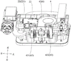
1. a base; 2. a housing; 22. cleaning the cavity; 221. opening the mouth; 3. a dust collection assembly; 31. a dust collection port; 32. an air return inlet; 33. an intake passage; 34. a dust collector; 341. a dust collecting box; 342. a drive member; 3421. a power source; 3422. a dust collecting motor; 35. an exhaust passage; 4. cleaning the equipment; 5. a body; 6. a drying assembly; 61. an air outlet; 611. a first air outlet; 612. a second air outlet; 62. a fan; 63. a ventilation member; 631. a first vent; 632. and a second ventilation member.
Detailed Description
In order to make the objects, technical solutions and advantages of the present invention more apparent, the present invention is further described in detail below with reference to the accompanying drawings and embodiments. It should be understood that the specific embodiments described herein are merely illustrative of the invention and are not intended to limit the invention.
The individual features described in the embodiments can be combined in any suitable manner without departing from the scope, for example different embodiments and aspects can be formed by combining different features. Various possible combinations of the various specific features of the invention are not described in detail to avoid unnecessary repetition.
In the following description, references to the term "first/second" - "merely distinguish between different objects and do not indicate that there is an identity or relationship between the objects. It should be understood that the description of the "upper", "lower", "outer" and "inner" directions as related to the orientation in the normal use state, and the "left" and "right" directions indicate the left and right directions indicated in the corresponding schematic drawings, and may or may not be the left and right directions in the normal use state.
It should be noted that the terms "comprises," "comprising," or any other variation thereof, are intended to cover a non-exclusive inclusion, such that a process, method, article, or apparatus that comprises a list of elements does not include only those elements but may include other elements not expressly listed or inherent to such process, method, article, or apparatus. Without further limitation, an element defined by the phrase "comprising an …" does not exclude the presence of other like elements in a process, method, article, or apparatus that comprises the element. "plurality" means greater than or equal to two.
As shown in fig. 1, the embodiment of the present invention provides a base 1 for a clothes treating apparatus, the base 1 is used for a cleaning apparatus 4 to rest, the cleaning apparatus 4 can be used for automatically cleaning dust, hair and the like on the ground, in case of a mop arranged on the cleaning apparatus 4, the cleaning apparatus 4 can perform a floor mopping operation on the ground after cleaning the ground, and the function of the cleaning apparatus in the embodiment of the present invention is not limited to the structure of the base. And the functions of the base 1 in the embodiment of the present invention include, but are not limited to, charging, dedusting, cleaning, drying, and sterilizing the cleaning device 4.
It should be noted that the base 1 in the embodiment of the present invention is applied to a clothes treatment apparatus, and the clothes treatment apparatus may include various forms, such as a washing machine, a spin dryer, and a laundry dryer. The specific application scenario of the laundry treating apparatus does not limit the structure of the base of the present invention.
As shown in fig. 1 and 2, a base 1 according to an embodiment of the present invention includes a housing 2 and a dust suction assembly 3. The inside of the housing 2 is provided with a cleaning cavity 22, the cleaning cavity 22 is used for the cleaning device 4 to stop, so as to realize the operations of charging and cleaning the cleaning device 4, and the outside of the cleaning cavity 22 is used for installing the components related to the operations of charging and cleaning. The dust collection assembly 3 in the embodiment of the present invention is disposed outside the cleaning chamber 22, and when the cleaning device 4 stops in the cleaning chamber 22, the dust collection assembly 3 can be used to collect dust and other garbage stored in the dust storage space inside the cleaning device 4, so as to empty the dust storage space inside the cleaning device 4, thereby facilitating the next dust removal operation of the cleaning device 4.
As shown in fig. 3, the dust suction assembly 3 is provided with a dust collecting port 31 adapted to communicate with the cleaning device 4, the dust collecting port 31 is used for sucking the dust such as dust stored in the dust storage space of the cleaning device 4; the dust suction assembly 3 is further provided with an air return opening 32 communicated with the cleaning cavity 22, and the air return opening 32 is used for guiding air in the dust suction assembly 3 out to the cleaning device 4. As shown in fig. 2, a dust storage space for storing dust and other garbage is provided inside the cleaning device 4, and an inlet and an outlet which are communicated with the dust storage space are further provided on the surface of the cleaning device 4, when the cleaning device 4 stops in the cleaning cavity 22, the outlet of the cleaning device 4 is in butt joint with the dust collection port 31 of the dust collection assembly 3, and the inlet of the cleaning device 4 is in butt joint with the air return port 32 of the dust collection assembly 3, so that the dust storage space of the cleaning device 4 is communicated with the dust collection assembly 3 and is sealed relative to the outside, and air can form a circulation air path between the dust storage space of the cleaning device 4 and the dust collection assembly 3, that is, air can circularly flow between the dust storage space and the dust collection assembly, and cannot flow to the outside of the cleaning device 4 and the dust collection assembly 3, and outside air cannot flow to the inside of the cleaning device 4 and the dust collection assembly 3.
It should be noted that the communication in the present invention may be direct communication, for example, the dust collecting port 31 is directly connected to the cleaning device 4 in a butt joint manner, so as to realize communication; it may also be indirect, such as the dust collection port 31 communicating with the cleaning device 4 via other passages or auxiliary devices.
In the embodiment of the invention, the dust collecting opening 31 of the dust collecting component 3 is butted with the outlet of the cleaning device 4, the air return opening 32 of the dust collecting component 3 is butted with the inlet of the cleaning device 4, the dust collecting component 3 and the cleaning device 4 form a circulating air path, the dust collecting component 3 sucks dust to the dust storage space of the cleaning device 4 through the dust collecting opening 31, the dust collecting component 3 filters the dust and conducts air, the air flows into the dust collecting component from the dust storage space to generate pressure difference, so that the dust storage space in the cleaning device generates negative pressure, the filtered air after passing through the dust collecting component can flow back to the dust storage space in the cleaning device through the air return opening under the action of the negative pressure, therefore, the air realizes internal circulation between the dust collecting component 3 and the cleaning device, the air continuously passes through the dust storage space and brings the dust in the dust storage space into the dust collecting component through the dust collecting opening, the dust collecting component continuously collects the dust and leads the filtered air back to the dust storage space, and circulating in sequence until the air completely transfers the dust in the dust storage space into the dust collection assembly, so that the dust collection assembly removes dust of the cleaning equipment.
The embodiment of the invention provides a base, the base 1 comprises a shell 2 and a dust suction assembly 3, a cleaning cavity 22 is arranged in the shell 2, the dust suction assembly 3 is provided with a dust collecting opening 31 and an air return opening 32 which are suitable for being communicated with a cleaning device 4, and the dust collecting opening 31 is used for sucking dust in the cleaning device 4. In the embodiment of the invention, the dust collection assembly 3 is provided with the dust collection port 31 and the air return port 32, and the dust collection port 31 and the air return port 32 are respectively butted with the cleaning equipment 4 under the state that the cleaning equipment 4 stops in the cleaning cavity 22, so that a circulating channel is formed between the dust collection assembly 3 and the cleaning equipment 4, gas is continuously circulated between the dust collection assembly 3 and the cleaning equipment 4, and dust in the cleaning equipment 4 can be transferred into the dust collection assembly 3 along with circulating airflow, so that the dust removal of the cleaning equipment 4 is realized; the dust transfer can be realized by adopting the internal circulation on the basis of improving the compactness of the base structure, and the circulation air path between the dust collection assembly and the cleaning equipment has good tightness, thereby being beneficial to improving the dust transfer efficiency; in addition, the base is applied to the clothes treatment equipment, so that the storage space is saved.
In some embodiments, the air return opening 32 can be directly connected to the atmosphere, so that air in the atmosphere can flow into the air return opening 32 and be blown into the cleaning device 4 through the air return opening 32, and it can be understood that the air blown into the cleaning device through the air return opening 32 can be either clean air after dust is filtered by the dust collection assembly 3 or air in the atmosphere.
In some embodiments, as shown in fig. 4, the structure of the housing is omitted in fig. 4 for the convenience of viewing, and the dust suction assembly 3 includes an air intake passage 33, a dust collector 34, and an air discharge passage 35. The air inlet passage 33 has opposite ends in the extending direction, wherein one end is provided as the dust collecting opening 31, and the other end of the air inlet passage 33 is connected with the dust collector 34, wherein the air inlet passage 33 can be provided as a hose so that the air inlet passage 33 can be matched with other components during the assembling process, and of course, the air inlet passage 33 can also be directly formed by the housing. In some embodiments, a rubber member may be disposed at the dust collecting port 31 of the air inlet passage 33, and the rubber member is disposed around the dust collecting port 31, so that the sealing performance of the connection between the dust collecting port and the cleaning device can be increased by the rubber member, thereby facilitating the efficiency of transferring the dust in the cleaning device to the dust collector 34. The dust collector 34 in the embodiment of the present invention is used to filter dust introduced from the dust collection port 31. As shown in fig. 4, one end of the exhaust channel 35 is connected to the dust collector 34, the other end of the exhaust channel 35 is provided with the air return opening 32, the exhaust channel is used for guiding the air filtered by the dust collector 34 out to the cleaning device, in some embodiments, the exhaust channel 35 may be provided as a soft channel, so that the exhaust channel 35 is matched with other components in the assembly process, the air return opening 32 of the exhaust channel 35 may be provided with a rubber member, the rubber member is disposed around the air return opening 32, and the sealing performance of the connection between the air return opening and the cleaning device can be increased by disposing the rubber member, thereby being beneficial to improving the efficiency of transferring the dust in the cleaning device to the dust collector 34.
As shown in fig. 4, the air circulates between the cleaning device 4 and the dust suction assembly 3, the air passes through the cleaning device 4, the dust in the cleaning device 4 flows into the dust collector 34 from the air inlet channel 33 along with the air, the dust collector 34 can filter the passing air, that is, the dust collector 34 collects the passing dust and conducts the passing air, the air flows from the dust collector 34 to the air outlet channel 35, the air flows back into the cleaning device 4 from the air outlet channel, the air carries the dust in the cleaning device 4 again, and the air circulates in turn to transfer the dust in the cleaning device 4 to the dust collector 34. According to the embodiment of the invention, the dust collection assembly is arranged into the air inlet channel, the dust collector and the air outlet channel, so that the air inlet channel and the air outlet channel are more easily matched with other components for assembly, the assembly difficulty of the dust collector is favorably reduced, the space utilization rate of the base is favorably improved, and the assembly size of the base is reduced.
In some embodiments, as shown in fig. 4, the dust collecting opening 31 is close to the dust collector 34 relative to the air return opening 32, and it can be understood that the dust collecting opening 31 is arranged between the air return opening 32 and the dust collector 34, so that the length of the air inlet passage 33 is smaller than that of the air outlet passage 35, and by setting the length of the air inlet passage 33 to be shorter, the embodiments of the present invention are beneficial to shorten the path for dust to flow from the cleaning device to the dust collector 34, thereby reducing the risk of dust remaining in the air inlet passage 33, increasing the fluency of the air inlet passage 33, and further improving the dust collection efficiency of the dust collector.
In some embodiments, as shown in FIG. 5, the front end of the cleaning chamber 22 is provided with an opening 221; in connection with fig. 2, the opening 221 is connected to the cleaning chamber 22, and it should be noted that the opening 221 represents an opening with a larger cross-sectional size, so that the cleaning device 4 can move from the opening 221 to the cleaning chamber 22 by providing the opening 221 in the cleaning chamber 22. The exhaust passage 35 bypasses from the rear end of the cleaning chamber 22 to the right end of the cleaning chamber 22 and is connected to the dust container 34. It should be noted that the front end of the cleaning chamber 22 can be regarded as the end close to the user, and the end far away from the user can be regarded as the rear end of the cleaning chamber 22. An air intake passage 33 and a dust collector 34 are also provided at the right end of the cleaning chamber 22.
According to the embodiment of the invention, the dust collection components are distributed at the rear end and the right end of the cleaning cavity, so that the dust collection components are distributed in two directions, the size of the dust collection components in one direction is reduced, the dust collection components are arranged side by side with the cleaning cavity, the whole height of the base is favorably reduced, the air inlet channel, the air exhaust channel and the dust collector are transversely arranged, the risk that impurities with large gravity cannot be upwards sucked into the dust collector due to longitudinal arrangement is reduced, and the risk that residual dust in the channel (the air inlet channel or the air exhaust channel) falls out of the channel and falls into the dust collector when a user takes out the dust collector can also be reduced.
In some embodiments, as shown in fig. 4, the air intake passage 33 is located between the cleaning chamber 22 and the dust collector 34 in the left-right direction. Air inlet channel 33 can set up to the shape of buckling structure, and air inlet channel 33 can extend along the fore-and-aft direction, and air inlet channel 33's collection dirt mouth 31 is located the rear end in clean chamber 22, and the air inlet channel 33 other end is connected with dust arrester 34, and through extending the setting with air inlet channel roughly along the fore-and-aft direction, satisfying under the shorter prerequisite of air inlet channel length, still be favorable to reducing whole dust absorption assembly's assembly size to improve the structural dimension of whole base.
In some embodiments, as shown in fig. 3, the dust collection port 31 and the return air port 32 are provided at intervals in the left-right direction. The interval shows that the distance between the dust collecting opening 31 and the air return opening 32 in the left-right direction is larger than a certain value, air enters the cleaning equipment from the air return opening and flows to the dust collecting opening through the cleaning equipment, the dust collecting opening and the air return opening are arranged at intervals, the flowing path of air flow in the cleaning equipment is favorably increased, accordingly, the air is favorably enabled to take away dust in the cleaning equipment as far as possible, the risk of the dust remaining in the cleaning equipment is reduced, and the dust removing efficiency of the dust collecting assembly on the cleaning equipment is improved.
In some embodiments, as shown in fig. 3, the distance L1 between the dust collection port 31 and the return air port 32 in the left-right direction is greater than 0.5 times the dimension L2 of the cleaning chamber 22 in the left-right direction. According to the embodiment of the invention, by limiting the distance between the dust collection opening and the air return opening and the size relation of the cleaning cavity, as the size of the cleaning cavity in the left-right direction is approximately consistent with the size of the cleaning equipment, the size relation of the dust collection opening, the air return opening and the cleaning equipment in the left-right direction can be further limited, the flowing path of the air flow in the cleaning equipment can be prolonged, the dust in the cleaning equipment can be taken away by the air as far as possible, and the dust removal effect of the dust collection assembly on the cleaning equipment is improved.
In some embodiments, as shown in fig. 3, the dust collection port 31 and the return air port 32 are respectively provided at opposite sides of the cleaning chamber 22 in the left-right direction. According to the embodiment of the invention, the dust collecting port and the air return port are respectively arranged on two opposite sides of the cleaning cavity, so that the gas can flow from one side in the left-right direction of the cleaning equipment to the other side in the left-right direction, and the path of the gas flowing in the cleaning cavity is improved on the premise of a certain size of the cleaning cavity, thereby improving the efficiency of driving dust in the cleaning equipment by the gas and improving the dust removal effect of the dust collection assembly.
In some embodiments, as shown in fig. 4, the dust collector 34 includes a dust bin 341 and a drive member 342. The dust collecting box 341 is connected to the other end of the air intake passage 33; wherein, the other end of the air intake path 33 indicates an end far from the dust collection port 31, and the dust collection box 341 is used for collecting dust introduced from the air intake path 33 and filtering gas introduced from the air intake path 33. In some embodiments, the other end of the air inlet channel 33 is connected to a side portion of the dust collecting box 341, the side portion indicates a position of the dust collecting box 341 around the up-down direction, the dust collecting box 341 has two opposite ends in the up-down direction, the two ends of the dust collecting box 341 in the up-down direction are defined as a top end and a bottom end in the embodiments of the present invention, and then a portion corresponding to the top end and the bottom end is defined as a side portion of the dust collecting box, and the embodiments of the present invention connect the other end of the air inlet channel 33 to the side portion of the dust collecting box, so that dust in the air has a smaller degree of overcoming the gravity action during the flowing process compared with a manner of connecting the other end of the air inlet channel to the top portion or the bottom portion of the dust collecting box, thereby reducing the risk of dust accumulation in the air inlet channel.
As shown in fig. 4, one end of the driving member 342 is connected to the dust box 341, the other end of the driving member 342 is connected to one end of the exhaust passage 35, and the driving member 342 is used for guiding the air flow from the dust collection opening 31 to the air return opening 32. The driving member 342 of the embodiment of the present invention can be used to disturb the flow of the air in the air inlet channel 33 or the air outlet channel 35, so that the air flows from the air inlet channel 33 to the air outlet channel 35, and when the cleaning device is connected to the dust suction assembly, the driving member can drive the air between the cleaning device and the dust suction assembly to realize internal circulation.
In some embodiments, as shown in fig. 4, the drive 342 includes a power source 3421 and a dust collection motor 3422. The power supply 3421 and the dust box 341 are stacked in the vertical direction, the vertical direction in the embodiment of the present invention may be used to indicate the vertical direction in the absolute coordinate system, and the plane formed by the front-back direction and the left-right direction may be used to indicate the direction of the horizontal plane in the absolute coordinate system. The power supply 3421 of the embodiment of the present invention can be used to convert ac power in the clothes treating apparatus into dc power for the dust collecting motor in the base. As shown in fig. 4, one end of the dust collection motor 3422 in the front-rear direction is connected to the dust collection case 341, and the other end of the dust collection motor 3422 in the front-rear direction is connected to the exhaust passage 35. In other words, the air inlet channel and the air outlet channel are connected to the two opposite sides of the dust collecting motor in the front-back direction, and the air inlet channel, the air outlet channel and the dust collecting motor are arranged in the horizontal direction, so that the assembly size of the base in the vertical direction is reduced, and the overall height of the base is reduced.
In some embodiments, the dust collection bin includes a bin, a drawer, and a filter. A first cavity is arranged in the box body, and one end of the first cavity in the front-back direction is opened; the inside second cavity that communicates dust collecting opening and return air inlet that is equipped with of suction hopper, the suction hopper can set up in first cavity along fore-and-aft direction translation ground, and under the condition of suction hopper setting at first cavity, the opening can be sealed to the suction hopper to first cavity and second cavity form airtight cavity, filter the piece setting in the second cavity, filter the piece and be used for filtering the gas that passes through the second cavity, and collect the dust that passes through the second cavity. The filter piece is detachably arranged in the second cavity, and when the dust in the filter piece is fully collected, the filter piece can be detached and replaced by a new filter piece.
Of course, in other embodiments, the structure of the dust collecting box includes but is not limited to the above-mentioned one, for example, the dust collecting box may be communicated with the sewage channel of the laundry treating apparatus, water in the sewage channel flows through the dust collecting box, and washes dust in the dust collecting box to the sewage outlet of the laundry treating apparatus, thereby directly discharging the dust in the dust collecting box to the outside of the laundry treating apparatus, simplifying user operation, and improving user experience.
As shown in fig. 1, the base 1 of the embodiment of the present invention further includes a drying assembly 6. Drying assembly 6 sets up outside clean chamber, and it is shown with fig. 3 to combine, drying assembly 6 is equipped with the air outlet 61 with clean chamber 22 intercommunication, and air outlet 61 is used for to the leading-in air current in clean chamber 22, and the air current blows to clean chamber 22 in through air outlet 61, and the air current blows to the moist mop of the cleaning device 4 of berthhing in clean chamber 22 on, and the moisture on the mop is taken away to the air current to play the air-drying effect to the mop. As shown in fig. 6, the drying assembly 6 is partially located at one end of the cleaning chamber 22 in the front-rear direction, and the other part is located at one end of the cleaning chamber 22 in the up-down direction. According to the embodiment of the invention, the drying components are distributed at one end in the front-back direction and one end in the up-down direction of the cleaning cavity, so that the drying components are dispersed in two directions, the size of the drying components in one direction is reduced, and part of the drying components and the cleaning cavity are arranged side by side in the front-back direction, so that the whole height of the base is favorably reduced.
In some embodiments, as shown in fig. 6, one end of the cleaning chamber 22 in the front-rear direction is provided with an opening 221, one end of the cleaning chamber 22 in the up-down direction is regarded as a top end of the cleaning chamber 22, and the drying assembly 6 is partially disposed at one end of the cleaning chamber 22 in the up-down direction, that is, the drying assembly 6 is partially disposed at the top end of the cleaning chamber 22. Another portion of drying assembly 6 may be disposed at an end of cleaning chamber 22 on the first side, that is, drying assembly 6 may be disposed at a rear end of cleaning chamber 22. In the embodiment of the invention, the drying components are distributed around the cleaning cavity, so that the assembly space of the drying components in one direction is favorably reduced, and the assembly size of the whole base is reduced.
In some embodiments, the drying assembly 6 includes a fan 62 and a vent 63. The blower 62 functions to increase the pressure of the gas by means of mechanical energy, wherein the blower 62 is disposed at one end of the cleaning chamber 22 in the up-down direction, that is, the blower 62 is disposed at the top of the cleaning chamber 22. As shown in fig. 6, one end of the ventilation member 63 is communicated with the fan 62, the other end of the ventilation member 63 is provided with an air outlet 61 (see fig. 3), the ventilation member 63 is arranged in a hollow manner, the ventilation member 63 is arranged at the rear end of the cleaning cavity 22, and the ventilation member 63 can be used for conducting the air flow generated by the fan 62 and guiding the air flow in the fan 62 to the cleaning cavity 22. According to the embodiment of the invention, the drying component is provided with the fan and the ventilation component, the drying component does not need to be arranged on one side of the cleaning cavity in a centralized manner, and the drying component can be distributed on different sides of the cleaning cavity, so that the overall height of the base can be reduced, and the assembly difficulty of the drying component can be reduced.
In some embodiments, as shown in fig. 6, the fan 62 has a dimension in the front-rear direction that is larger than a dimension of the fan 62 in the up-down direction. In a normal use state of the fan, the size of the fan 62 in the vertical direction is larger than the size of the fan 62 in the horizontal direction, and the fan 62 in the embodiment of the present invention is placed horizontally, that is, the size of the fan 62 in the vertical direction is smaller than the size of the fan in the horizontal direction, which is beneficial to reducing the space occupied by the fan in the vertical direction and reducing the size of the base in the vertical direction.
In some embodiments, as shown in fig. 6, the extending direction of the ventilation member 63 is parallel to the up-down direction. It should be noted that, the extending direction of the ventilation member 63 indicates the length direction of the ventilation member 63, and the length direction of the ventilation member is consistent with the upper and lower directions, so that the space occupied by the ventilation member in the front-rear direction is favorably reduced, the compactness of assembling components in the housing is favorably improved, and the space utilization rate in the housing is improved.
In some embodiments, as shown in fig. 6, a plurality of ventilation members 63 are provided, the upper ends of the plurality of ventilation members 63 are all communicated with the fan 62, that is, the air flow generated at the fan 62 is dispersedly flowed into the plurality of ventilation members 63, the lower ends of the plurality of ventilation members 63 are arranged at intervals in the left-right direction, the air flow is respectively blown to the cleaning cavity from the other ends of the plurality of ventilation members 63, and is respectively blown to different positions of the cleaning device 4, so that the drying efficiency of the cleaning device is improved.
In some embodiments, as shown in fig. 6, the ventilation member 63 includes a first ventilation member 631 and a second ventilation member 632, one end of the first ventilation member 631 is communicated with the fan 62, the other end of the first ventilation member 631 is a first air outlet 611, one end of the second ventilation member 632 is communicated with the fan 62, and the other end of the second ventilation member 632 is a second air outlet 612; in some embodiments, two mops may be provided in the cleaning device 4, each side by side in the left-right direction. As shown in fig. 3, a distance L3 between the first outlet 611 and the second outlet 612 in the left-right direction is greater than or equal to a first dimension, which is 0.2 times a dimension L2 of the cleaning chamber 22 in the left-right direction, and is less than or equal to a second dimension, which is 0.6 times a dimension L2 of the cleaning chamber in the left-right direction in the embodiment of the present invention. According to the embodiment of the invention, the distance between the first air outlet and the second air outlet is limited within a certain range, so that air flows guided out by the first air outlet and the second air outlet can be uniformly blown onto a mop of the cleaning equipment, and the drying efficiency of the cleaning equipment is improved. In some embodiments, as shown in fig. 6, the first air outlet 611 and the second air outlet 612 are symmetrically disposed relative to a central line of the cleaning cavity 22 in the left-right direction, and the first air outlet and the second air outlet are symmetrically disposed in the left-right direction in the embodiments of the present invention, which is beneficial to improving the drying efficiency of the air flow on the cleaning device in the cleaning cavity.
In some embodiments, as shown in fig. 6, a portion of the first ventilation member 631 adjacent to the blower 62 extends in the left-right direction, a portion of the first ventilation member 631 adjacent to the first air outlet 611 extends in the up-down direction, a portion of the second ventilation member 632 adjacent to the blower 62 extends in the left-right direction, and a portion of the second ventilation member 632 adjacent to the second air outlet 612 extends in the up-down direction. That is to say, the end utensil that first ventilation piece 631 and second ventilation piece 632 are close to fan 62 is connected with fan 62, and all extend along the horizontal direction, the part that first ventilation piece 631 and second ventilation piece 632 keep away from fan 62 is at the left and right sides direction interval, and all extend along upper and lower direction, be favorable to with first air outlet 611 and second air outlet 612 at the second side interval and with the one end intercommunication of first ventilation piece 631 with the one end of second ventilation piece 632, can be with the bottom of air current dispersion and direction clean chamber, make the air current can be even the dispersion to the position that two mops in the cleaning equipment correspond, thereby improve cleaning equipment's air-dry efficiency.
In some embodiments, as shown in fig. 3, the air outlet 61 is close to the bottom end of the cleaning chamber 22 in the up-down direction. The up-down direction may represent the vertical direction of the base in normal use, and the corresponding lower end shown in fig. 3 represents the bottom end of the cleaning chamber 22. It should be noted that the approach in the embodiment of the present invention indicates that the distance between the air outlet 61 and the bottom end of the cleaning cavity 22 is less than or equal to 0.4 times the size of the cleaning cavity 22 in the vertical direction. According to the embodiment of the invention, the air outlet is arranged close to the bottom end of the cleaning cavity in the vertical direction, so that the distance between the air outlet and a mop in the cleaning equipment is favorably shortened, and the air guided out from the air outlet is favorably directly blown onto the mop, thereby reducing the dissipation of air flow and further improving the drying efficiency of the cleaning equipment.
In some embodiments, the drying assembly further comprises a heating element. And the heating element is arranged in the ventilation element and is used for heating the airflow passing through the ventilation element. Through heating member heating air current for the temperature of air current risees, blows to cleaning equipment's mop surface at high temperature air current, and high temperature air current can carry out heat-conduction with the mop, makes the temperature of mop rise for the evaporation of moisture in the mop, and moisture in the mop flows away along with the air current, realizes the fast drying of mop.
The embodiment of the present invention further provides a clothes treating apparatus, as shown in fig. 6, which includes a body 5 and the pedestal 1 according to any one of the above embodiments. The body 5 is used for realizing operations such as soaking, washing and drying for clothes, and the base 1 is arranged at one end of the body 5 in the vertical direction. Wherein, the up-down direction represents a vertical direction in an absolute coordinate system, that is, the pedestal 1 is disposed at the bottom of the laundry treating apparatus, and in a case where the laundry treating apparatus is placed on the floor, the pedestal 1 is closer to the floor than the body 5, thereby facilitating the cleaning apparatus to move into the cleaning chamber 22 through the opening.
The above description is only a preferred embodiment of the present invention, and is not intended to limit the scope of the present invention.
Claims (10)
1. A base, comprising:
the cleaning device comprises a shell, a cleaning device and a control device, wherein a cleaning cavity for the stop of the cleaning device is formed in the shell;
the dust collection assembly is arranged outside the cleaning cavity and is provided with a dust collection port suitable for being communicated with the cleaning equipment so as to absorb dust in the cleaning equipment; the dust collection assembly is further provided with a return air inlet communicated with the cleaning equipment so as to guide air to the cleaning equipment through the return air inlet.
2. The base of claim 1, wherein the suction assembly comprises:
one end of the air inlet channel is provided with the dust collecting opening;
a dust collector connected to the other end of the air inlet passage to filter dust introduced from the dust collecting port;
and one end of the exhaust channel is connected with the dust collector, and the other end of the exhaust channel is provided with the air return opening so as to guide the gas filtered by the dust collector to the cleaning equipment.
3. The base of claim 2, wherein the dirt collection opening is closer to the dirt collector than the return air opening.
4. The base of claim 3, wherein the front end of the cleaning chamber is provided with an opening, the dust collecting opening and the air return opening are respectively arranged at the left side and the right side of the rear end of the cleaning chamber, the dust collector is arranged at the right end of the cleaning chamber, and the exhaust passage bypasses from the rear end of the cleaning chamber to the right end of the cleaning chamber and is connected with the dust collector.
5. The base of claim 4, wherein the air intake passage is located between the cleaning chamber and the dust collector in a left-right direction.
6. The base of claim 5, wherein a distance between the dust collection port and the air return port in the left-right direction is greater than 0.5 times a size of the cleaning chamber in the left-right direction.
7. The base of any of claims 2-6, wherein the dust collector comprises:
the dust collecting box is connected with the other end of the air inlet channel;
and one end of the driving piece is connected with the dust collection box, and the other end of the driving piece is connected with one end of the exhaust channel so as to guide the airflow to flow from the dust collection port to the air return port.
8. The base of claim 7, wherein the dust collection bin comprises:
the box body is internally provided with a first cavity, and the front end of the first cavity is opened;
the interior of the suction bucket is provided with a second cavity communicated with the dust collecting port and the air return port, and the suction bucket can be arranged in the first cavity in a translation manner along the front-back direction;
a filter element disposed within the second cavity to filter gas passing through the second cavity.
9. The base of claim 8, wherein the drive member comprises:
the power supply is arranged above the dust collecting box;
the front end of the dust collection motor is connected with the dust collection box, and the rear end of the dust collection motor is connected with the exhaust channel.
10. A laundry treating apparatus, comprising:
a body;
the base of any of claims 1-9, said base being disposed at a lower end of said body.
Priority Applications (3)
| Application Number | Priority Date | Filing Date | Title |
|---|---|---|---|
| CN202210540760.6A CN114921932A (en) | 2022-05-17 | 2022-05-17 | Base and clothes treatment equipment |
| EP23806810.0A EP4339349A4 (en) | 2022-05-17 | 2023-05-11 | Base and clothing treatment device |
| PCT/CN2023/093534 WO2023221858A1 (en) | 2022-05-17 | 2023-05-11 | Base and clothing treatment device |
Applications Claiming Priority (1)
| Application Number | Priority Date | Filing Date | Title |
|---|---|---|---|
| CN202210540760.6A CN114921932A (en) | 2022-05-17 | 2022-05-17 | Base and clothes treatment equipment |
Publications (1)
| Publication Number | Publication Date |
|---|---|
| CN114921932A true CN114921932A (en) | 2022-08-19 |
Family
ID=82809286
Family Applications (1)
| Application Number | Title | Priority Date | Filing Date |
|---|---|---|---|
| CN202210540760.6A Pending CN114921932A (en) | 2022-05-17 | 2022-05-17 | Base and clothes treatment equipment |
Country Status (1)
| Country | Link |
|---|---|
| CN (1) | CN114921932A (en) |
Cited By (2)
| Publication number | Priority date | Publication date | Assignee | Title |
|---|---|---|---|---|
| WO2023221858A1 (en) * | 2022-05-17 | 2023-11-23 | 无锡小天鹅电器有限公司 | Base and clothing treatment device |
| WO2024113978A1 (en) * | 2022-11-30 | 2024-06-06 | 无锡小天鹅电器有限公司 | Dust collector, sweeper base station, sweeper, and cleaning device |
Citations (6)
| Publication number | Priority date | Publication date | Assignee | Title |
|---|---|---|---|---|
| JP2013013539A (en) * | 2011-07-04 | 2013-01-24 | Panasonic Corp | Dust collector for indoor use, and program for making the dust collector function |
| US10590593B1 (en) * | 2018-10-02 | 2020-03-17 | Haier Us Appliance Solutions, Inc. | Lint cleaning assembly for a dryer appliance |
| CN113062091A (en) * | 2021-04-19 | 2021-07-02 | 创维电器股份有限公司 | Clothes dryer or washing machine base with sweeping robot |
| CN214259225U (en) * | 2020-11-19 | 2021-09-24 | 深圳市杉川机器人有限公司 | Dust collection station and cleaning system |
| CN114457545A (en) * | 2022-02-21 | 2022-05-10 | 青岛海尔洗衣机有限公司 | Laundry appliance |
| CN217324645U (en) * | 2022-05-17 | 2022-08-30 | 无锡小天鹅电器有限公司 | Base and clothes treatment equipment |
-
2022
- 2022-05-17 CN CN202210540760.6A patent/CN114921932A/en active Pending
Patent Citations (6)
| Publication number | Priority date | Publication date | Assignee | Title |
|---|---|---|---|---|
| JP2013013539A (en) * | 2011-07-04 | 2013-01-24 | Panasonic Corp | Dust collector for indoor use, and program for making the dust collector function |
| US10590593B1 (en) * | 2018-10-02 | 2020-03-17 | Haier Us Appliance Solutions, Inc. | Lint cleaning assembly for a dryer appliance |
| CN214259225U (en) * | 2020-11-19 | 2021-09-24 | 深圳市杉川机器人有限公司 | Dust collection station and cleaning system |
| CN113062091A (en) * | 2021-04-19 | 2021-07-02 | 创维电器股份有限公司 | Clothes dryer or washing machine base with sweeping robot |
| CN114457545A (en) * | 2022-02-21 | 2022-05-10 | 青岛海尔洗衣机有限公司 | Laundry appliance |
| CN217324645U (en) * | 2022-05-17 | 2022-08-30 | 无锡小天鹅电器有限公司 | Base and clothes treatment equipment |
Cited By (2)
| Publication number | Priority date | Publication date | Assignee | Title |
|---|---|---|---|---|
| WO2023221858A1 (en) * | 2022-05-17 | 2023-11-23 | 无锡小天鹅电器有限公司 | Base and clothing treatment device |
| WO2024113978A1 (en) * | 2022-11-30 | 2024-06-06 | 无锡小天鹅电器有限公司 | Dust collector, sweeper base station, sweeper, and cleaning device |
Similar Documents
| Publication | Publication Date | Title |
|---|---|---|
| CN114921932A (en) | Base and clothes treatment equipment | |
| US20200329928A1 (en) | Hand-hold vacuum cleaner | |
| KR101892653B1 (en) | Electric vacuum cleaner | |
| EP1074212B1 (en) | Vacuum cleaner | |
| KR20150008895A (en) | Autonomous vacuum cleaner | |
| CN217324645U (en) | Base and clothes treatment equipment | |
| US20240138644A1 (en) | Cleaner | |
| KR102370168B1 (en) | Induction structure of the mite removal device and the mite removal device | |
| CN113243856A (en) | Base station equipment with storage device and surface cleaning system | |
| CN215937242U (en) | Cleaning system and cleaning equipment | |
| CN113413098B (en) | Cleaning system | |
| CN217324643U (en) | Base and clothes treatment equipment | |
| WO2023221858A1 (en) | Base and clothing treatment device | |
| CN218606448U (en) | Cleaning device and cleaning system | |
| CN208988738U (en) | A kind of cleaning device applied in cleaning equipment | |
| CN210330460U (en) | Hand-held cleaning device | |
| CN206651793U (en) | Dust collector for removing mites | |
| CN218500643U (en) | Clean basic station | |
| TWI842021B (en) | Cleaner | |
| CN218356017U (en) | Dehumidification removes mite structure and cleaning device | |
| CN216048779U (en) | Dehydrating unit of electric power safety tool cabinet | |
| CN114680054B (en) | Pet drying machine | |
| CN213665081U (en) | Dust box and sweeping robot with same | |
| CN218186595U (en) | Cleaning device | |
| CN213488641U (en) | Industrial floor washing machine with good heat dissipation effect |
Legal Events
| Date | Code | Title | Description |
|---|---|---|---|
| PB01 | Publication | ||
| PB01 | Publication | ||
| SE01 | Entry into force of request for substantive examination | ||
| SE01 | Entry into force of request for substantive examination |