CN114902807A - Light tracking assembly for solar and wind energy - Google Patents
Light tracking assembly for solar and wind energy Download PDFInfo
- Publication number
- CN114902807A CN114902807A CN202080074034.9A CN202080074034A CN114902807A CN 114902807 A CN114902807 A CN 114902807A CN 202080074034 A CN202080074034 A CN 202080074034A CN 114902807 A CN114902807 A CN 114902807A
- Authority
- CN
- China
- Prior art keywords
- extension arm
- solar panel
- angle
- wind turbine
- axis
- Prior art date
- Legal status (The legal status is an assumption and is not a legal conclusion. Google has not performed a legal analysis and makes no representation as to the accuracy of the status listed.)
- Pending
Links
- 238000000034 method Methods 0.000 claims abstract description 7
- 230000005611 electricity Effects 0.000 claims description 7
- 238000003306 harvesting Methods 0.000 abstract description 6
- 230000002354 daily effect Effects 0.000 description 3
- 230000002452 interceptive effect Effects 0.000 description 2
- 238000003491 array Methods 0.000 description 1
- 230000002301 combined effect Effects 0.000 description 1
- 238000010276 construction Methods 0.000 description 1
- 230000001186 cumulative effect Effects 0.000 description 1
- 230000003203 everyday effect Effects 0.000 description 1
- 230000005484 gravity Effects 0.000 description 1
- 238000004519 manufacturing process Methods 0.000 description 1
Images
Classifications
-
- H—ELECTRICITY
- H02—GENERATION; CONVERSION OR DISTRIBUTION OF ELECTRIC POWER
- H02S—GENERATION OF ELECTRIC POWER BY CONVERSION OF INFRARED RADIATION, VISIBLE LIGHT OR ULTRAVIOLET LIGHT, e.g. USING PHOTOVOLTAIC [PV] MODULES
- H02S10/00—PV power plants; Combinations of PV energy systems with other systems for the generation of electric power
- H02S10/10—PV power plants; Combinations of PV energy systems with other systems for the generation of electric power including a supplementary source of electric power, e.g. hybrid diesel-PV energy systems
- H02S10/12—Hybrid wind-PV energy systems
-
- F—MECHANICAL ENGINEERING; LIGHTING; HEATING; WEAPONS; BLASTING
- F03—MACHINES OR ENGINES FOR LIQUIDS; WIND, SPRING, OR WEIGHT MOTORS; PRODUCING MECHANICAL POWER OR A REACTIVE PROPULSIVE THRUST, NOT OTHERWISE PROVIDED FOR
- F03D—WIND MOTORS
- F03D9/00—Adaptations of wind motors for special use; Combinations of wind motors with apparatus driven thereby; Wind motors specially adapted for installation in particular locations
- F03D9/007—Adaptations of wind motors for special use; Combinations of wind motors with apparatus driven thereby; Wind motors specially adapted for installation in particular locations the wind motor being combined with means for converting solar radiation into useful energy
-
- H—ELECTRICITY
- H02—GENERATION; CONVERSION OR DISTRIBUTION OF ELECTRIC POWER
- H02S—GENERATION OF ELECTRIC POWER BY CONVERSION OF INFRARED RADIATION, VISIBLE LIGHT OR ULTRAVIOLET LIGHT, e.g. USING PHOTOVOLTAIC [PV] MODULES
- H02S20/00—Supporting structures for PV modules
- H02S20/10—Supporting structures directly fixed to the ground
-
- H—ELECTRICITY
- H02—GENERATION; CONVERSION OR DISTRIBUTION OF ELECTRIC POWER
- H02S—GENERATION OF ELECTRIC POWER BY CONVERSION OF INFRARED RADIATION, VISIBLE LIGHT OR ULTRAVIOLET LIGHT, e.g. USING PHOTOVOLTAIC [PV] MODULES
- H02S20/00—Supporting structures for PV modules
- H02S20/30—Supporting structures being movable or adjustable, e.g. for angle adjustment
- H02S20/32—Supporting structures being movable or adjustable, e.g. for angle adjustment specially adapted for solar tracking
-
- H—ELECTRICITY
- H02—GENERATION; CONVERSION OR DISTRIBUTION OF ELECTRIC POWER
- H02S—GENERATION OF ELECTRIC POWER BY CONVERSION OF INFRARED RADIATION, VISIBLE LIGHT OR ULTRAVIOLET LIGHT, e.g. USING PHOTOVOLTAIC [PV] MODULES
- H02S40/00—Components or accessories in combination with PV modules, not provided for in groups H02S10/00 - H02S30/00
- H02S40/30—Electrical components
- H02S40/38—Energy storage means, e.g. batteries, structurally associated with PV modules
-
- Y—GENERAL TAGGING OF NEW TECHNOLOGICAL DEVELOPMENTS; GENERAL TAGGING OF CROSS-SECTIONAL TECHNOLOGIES SPANNING OVER SEVERAL SECTIONS OF THE IPC; TECHNICAL SUBJECTS COVERED BY FORMER USPC CROSS-REFERENCE ART COLLECTIONS [XRACs] AND DIGESTS
- Y02—TECHNOLOGIES OR APPLICATIONS FOR MITIGATION OR ADAPTATION AGAINST CLIMATE CHANGE
- Y02E—REDUCTION OF GREENHOUSE GAS [GHG] EMISSIONS, RELATED TO ENERGY GENERATION, TRANSMISSION OR DISTRIBUTION
- Y02E10/00—Energy generation through renewable energy sources
- Y02E10/50—Photovoltaic [PV] energy
Landscapes
- Engineering & Computer Science (AREA)
- Life Sciences & Earth Sciences (AREA)
- Sustainable Development (AREA)
- Sustainable Energy (AREA)
- Power Engineering (AREA)
- Chemical & Material Sciences (AREA)
- Combustion & Propulsion (AREA)
- Mechanical Engineering (AREA)
- General Engineering & Computer Science (AREA)
- Wind Motors (AREA)
Abstract
An apparatus and method for harvesting renewable energy includes a solar panel and a wind turbine mounted on the same extension arm. In this combination, as the extension arm rotates on the support rod, the solar panel simultaneously rotates through a direction arc θ and a tilt arc Φ according to a predetermined daily schedule based on the time of day and latitude of the device. Furthermore, as the solar panel moves, the wind turbine is free to follow the wind direction and maximize its collection of wind energy. To further maximize the energy harvesting capability of the apparatus, the wind turbine is positioned on the extension arm to remain off the solar panel, facing away from the sun and to remain undisturbed by wind currents that may be caused by the solar panel.
Description
Technical Field
The present invention relates generally to apparatus, systems and methods for harvesting electrical energy for commercial use from sources such as solar arrays, wind turbines and utility grids. In particular, the invention relates to an apparatus comprising a solar panel and a wind turbine in combination, which operate together without interfering with each other and with their respective operation. The invention has particular, but not exclusive, application as a device for harvesting renewable energy from different sources, having different energy harvesting capabilities, thereby further optimising the combined renewable and publicly available energy harvesting capabilities.
Background
In many cases, it is desirable to have a power source that may not otherwise be available, which may in fact be the case for any of several different reasons. When using renewable energy sources, factors such as location, climate conditions, accessibility, and cost are important considerations in determining how best to provide power.
In recent years, the availability of renewable energy sources has provided great flexibility in determining how to extend the availability of power sources. For example, wind and solar energy systems can be more localized and more mobile than other sources of electrical energy. Therefore, these sources of renewable energy are being effectively commercially exploited.
With particular attention to solar and wind energy as renewable energy sources, it is clear that the appliances relying on these different meteorological phenomena are structurally different and they have different capabilities, it being important that, although these phenomena are mutually exclusive for the respective operations, their outputs are cumulative. The result here is that each energy source, when used together, can operate independently and the combined effect of the different appliances (i.e. wind and sun) can continue to produce electricity over an extended daily duty cycle. Thus, as a practical matter, it may be desirable to integrate these instruments for their deployment. Furthermore, if available, it may be desirable to integrate a combination of wind and solar instruments with the utility grid.
In order to optimize the integrated wind/solar generator, the respective operational capabilities of the generators must be compatible with each other. Specifically, their respective operations should not interfere with natural phenomena that are the source of the other operation. For example, a solar power generator (e.g., a solar panel) must not be in the shadow of a wind power generator. In other words, the wind generator must remain "behind the sun" off the solar generator. On the other hand, the wind generator must be positioned sufficiently "downwind" from the solar generator so that the solar generator does not operationally interfere with the wind generator.
In view of the above, it is an object of the present invention to provide an integrated system that employs a combination of wind and solar generators to generate electricity. It is another object of the present invention to provide an integrated system for collecting solar and wind energy that allows the solar components (e.g., solar panels) to be continuously oriented with respect to the path of the sun. It is a further object of the present invention to provide an integrated system wherein the solar and wind energy components are mounted together as the same structural assembly for independent non-interfering operation. It is another object of the present invention to provide an integrated wind/solar generator that can be connected to a utility grid for combined use of different energy sources. It is a further object of the present invention to provide an integrated solar/wind power generator system that is simple to use, easy to manufacture, and relatively cost effective.
Disclosure of Invention
The present invention is a renewable energy system that employs an appliance that combines the use of solar and wind energy to generate electricity. As an integrated system, the present invention is created as a compact unit that can be permanently installed at a particular location, connected to a utility grid operation, or constructed as a mobile unit that can be periodically repositioned as needed or desired. For either embodiment (permanent or mobile), it is an important feature of the invention that the sun and wind components are independently operable. Furthermore, it is important that these components do not interfere with each other's operation.
Structurally, the system for collecting and storing renewable energy (i.e. the device) according to the invention comprises a support bar defining a bar axis. The extension arm is horizontally arranged on the support rod and is vertical to the rod axis of the support rod. Further, the extension arm is mounted for rotation on the support rod about the rod axis in a plane perpendicular to the rod axis.
A solar panel is mounted at one end of the extension arm for collecting solar energy. Preferably, the solar panel will have a plurality of photovoltaic cells mounted in an array on the solar panel. And it will tilt at a variable angle phi with respect to the rod axis. More specifically, the solar panel is mounted on the extension arm for rotation by a predetermined angle Φ about a horizontal axis perpendicular to the extension arm and perpendicular to the rod axis. Furthermore, a wind turbine is mounted at the other end on the extension arm for collecting wind energy. So mounted, the wind turbine is free to rotate about an axis parallel to the axis of the rod by an angle ψ.
The apparatus further comprises a motor for rotating the extension arm through a directional angle theta and for rotating the solar panel through a predetermined angle phi. Both rotations are done simultaneously according to a predetermined schedule. In particular, the focus here is to maintain the orientation of the solar panels during the day to optimally absorb solar energy. In a combination of the above components, the invention comprises an accumulator connected to the solar panel and to the wind turbine for storing the collected energy.
For the assembly of the system of the present invention, it should be understood that the solar panel has a weight W s And the wind turbine has a weight W w . In view of this, the extension arm will have a point of equilibrium between its first and second ends, wherein the weight W of the wind turbine w At a distance d from the equilibrium point w Acts on the extension arm and the weight W of the solar panel s At a distance d from the equilibrium point s Will counterbalance each other (W) acting on the extension arm w d w =W s d s ). Furthermore, in view of preventing operational interference between the wind turbine and the solar panel, the wind turbine is preferably located at a vertical height h above the extension arm w To (3). In particular, the height h is selected w And a distance d w And d s To position the wind turbine on the apparatus to avoid interference with the wind turbine by turbulent wind flow that may be caused by the solar panels. As disclosed above, the position of the wind turbine on the extension arm is established away from the solar panel, facing away from the sun and out of shadow.
Operationally, it is contemplated that the motors for rotating the extension arm and solar panel will be programmed with a predetermined schedule based on the time of day and the path of the sun during the day. Thus, the angle θ is at the initial angle θ i And final angle theta f A directional arc extending therebetween. Furthermore, the angle Φ is at the angle Φ 1 And phi 2 A sloped arc extending therebetween. Establishing a directional arc θ per day according to the predetermined schedule, as indicated i :θ f And the oblique arc phi 1 :Φ 2 。
In detail, for the predetermined schedule, θ is established with respect to sunrise of operation day i And theta is established with respect to the sunset of the operation day f . Further, Φ is established relative to sunrise and sunset of the operating day 1 And establishing phi with respect to noon of the operating day 2 . Further, the directional arc and the oblique arc are established relative to a latitude of the device.
As mentioned above, the wind/solar generator of the present invention can be connected to a public power grid. If so, the present invention contemplates being able to control the battery to collect and then distribute electrical energy according to a priority protocol. In particular, electricity taken from the utility grid is only used after electricity from the wind/solar generator has been used. On the other hand, if excess energy generated by the wind/solar generator is available, it may be sent to the utility grid to provide additional revenue.
Drawings
The novel features of the present invention, as well as the invention itself, both as to its structure and its operation, will be best understood from the accompanying drawings, taken in conjunction with the accompanying description, in which like reference numerals refer to like parts, and in which:
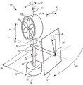
FIG. 1 is a perspective view of the apparatus of the present invention;
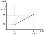
FIG. 2 is a directional arc θ contemplated for the present invention i :θ f A graphical representation of (a); and is
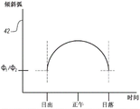
FIG. 3 is a skewed arc Φ contemplated for the present invention 1 :Φ 2 Is shown in the figure.
Detailed Description
Referring initially to FIG. 1, an apparatus for collecting and storing renewable energy in accordance with the present invention is shown and generally designated 10. As shown, the apparatus 10 includes a solar panel 12 and a wind turbine 14. For the present invention, the solar panel 12 may be an array of photovoltaic cells, which are presented in a manner well known in the relevant art for the purpose of converting solar energy into electrical energy. The wind turbine 14 used in the present invention is essentially a windmill 16, which may or may not be mounted in a shroud 18. For purposes of the present invention, wind turbine 14 may be of any type well known in the relevant art that is capable of converting wind energy into electrical energy.
Still referring to fig. 1, it will be seen that the apparatus 10 includes a base 20 that stabilizes the apparatus 10. Mounted within base 20 or otherwise operatively connected to apparatus 10 are a motor (not shown) and a battery (not shown). As contemplated by the present invention, the motor is used to reconfigure the apparatus 10 in a predetermined manner as fully disclosed hereinafter. Furthermore, a battery is provided to store electrical energy generated by the solar panels 12 and/or the wind turbine 14. A portion of the electrical energy stored in the battery will be used to operate the device 10. However, the excess electrical energy may be used for other purposes deemed necessary or appropriate.
Structurally, the apparatus 10 includes a support rod 22, the support rod 22 defining a rod axis 24. The rod axis 24 is generally vertically oriented, as contemplated by the present invention. Mounted on the support bar 22 is an extension arm 26 defining a horizontal axis 28. Further mounted on extension arm 26 is a lift arm 30 defining a vertical axis 32. In this combination, extension arm 26 is perpendicular to support bar 22, and lift arm 30 is parallel to support bar 22 and perpendicular to extension arm 26.
The structure of the apparatus 10 of the present invention also includes a wind vane 34 secured to the shroud 18. In response to the reaction of the wind vane 34, the wind turbine 14 will rotate through an angle ψ about the vertical axis 32. The wind turbine 14 can be rotated through an arc of 360 ° depending on the wind direction.
The several dimensions shown in fig. 1 are particularly important during assembly of the device 10. Specifically, these dimensions include: i) h is w I.e. the height of the centre of gravity of the windmill 16 above the horizontal axis 28; ii) d w I.e., the distance of the vertical axis 32 to the balance point 36 on the rod axis 24; iii) d s I.e., the distance between the attachment point 38 connecting the solar panel 12 to the extension arm 26 and the balance point 36. Typically, these dimensions are established in view of the structural stability and operational capabilities of the apparatus 10.
For operation of apparatus 10, a motor (not shown) mounted in support base 20 is programmed to rotate extension arm 26 through a predetermined directional angle θ. The motor is also programmed to rotate the solar panel 12 through a predetermined tilt angle Φ. Rotation of the extension arm 26 and rotation of the solar panel 12 are both accomplished according to a predetermined schedule.
In detail, extension arm 26 rotates in a horizontal plane through an orientation angle θ measured in orientation arc 40. More specifically, as shown in FIG. 1 and graphically represented in FIG. 2, directional arc 40 is at an initial angle θ i And final angle theta f (i.e. theta) i :θ f ) Extending therebetween. Establishing an initial orientation angle theta with respect to the sunrise of the operation day on a daily basis according to the predetermined schedule i And the direction angle theta is steadily increased during the day until a final direction angle theta is established with respect to the sunset of the same operation day f . As will be understood by those skilled in the art, the directional arc will traverse each day, and the length of directional arc 40 (i.e., θ) 1 :θ f ) Will change every day.
The motor also rotates the solar panel 12 as part of a predetermined schedule. Specifically, for such rotation as shown in FIG. 1 and illustrated in FIG. 3, the tilt angle Φ is at an angle Φ 1 Sum angle phi 2 Extend through an oblique arc 42 (i.e., # 1 :Φ 2 ). However, unlike the direction angle θ, the tilt angle Φ is measured in the vertical plane. Further, for the oblique arc 42, Φ is established daily with respect to the sunrise and sunset of the operation day 1 . On the other hand, Φ is established at noon with respect to the operation day 2 . Arc of direction 40 and inclinationThe oblique arcs 42 are established together relative to the latitude of the device 10. In view of the above, it is to be remembered that the angle ψ of rotation of the wind turbine 14 about the vertical axis 32 will extend through a 360 ° arc and is time independent.
For support and stability considerations related to the present invention, the solar panel 12 will have a weight W s And the wind turbine 14 will have a weight W w . In addition, extension arm 26 will have a point of equilibrium 36 between its endpoints. Importantly, the balance point 36 will be located on the support bar 22 and the weight W of the wind turbine 14 w At a distance d from the equilibrium point 36 w Acts on extension arm 26. Further, the weight W of the solar panel 12 s At a distance d from the equilibrium point 36 s Acts on extension arm 26. In such a combination, W will be w And W s Counterbalance (i.e. W) w d w =W s d s )。
The result of choosing the appropriate dimensions for the above-mentioned structural combinations includes the fact that: the wind turbine 14 will always be positioned away from the sun from the solar panel 12. Furthermore, wind turbine 14 will be positioned on extension arm 26 at a vertical height h above extension arm 26 w To avoid interference with the wind flow through the wind turbine 14 which might otherwise be caused by the turbulent airflow caused by the solar panels 12.
For alternative embodiments of the invention, the wind/solar generator may be connected to the utility grid in some manner. In particular, it is envisaged that a connection may be made directly to an existing utility, such as a lamppost (not shown), or a commercially available electrical grid outlet. In any case, electricity drawn from the utility grid will preferentially use the energy from the wind/solar generator so that the energy collected from the wind/solar generator is used first. In addition, excess energy can be returned to the grid for revenue generation purposes.
While the particular light tracking assembly for solar and wind power as herein shown and disclosed in detail is fully capable of obtaining the objects and providing the advantages herein before stated, it is to be understood that it is merely illustrative of the presently preferred embodiments of the invention and that no limitations are intended to the details of construction or design herein shown other than as described in the appended claims.
Claims (20)
1. A device for collecting and storing renewable energy, the device comprising:
a support bar defining a bar axis;
an extension arm mounted on the support rod, wherein the extension arm has a first end and a second end;
a solar panel mounted on the extension arm and at the first end of the extension arm for collecting solar energy, wherein the solar panel defines a panel axis that is inclined at an angle Φ with respect to the rod axis;
a wind turbine mounted on the extension arm and at the second end of the extension arm for collecting wind energy, wherein the wind turbine is free to rotate through an angle ψ about an axis parallel to the rod axis; and
a battery connected to the solar panel and to the wind turbine to store the collected energy.
2. The device of claim 1, wherein the extension arm is mounted for rotation on the support rod about the rod axis in a plane perpendicular to the rod axis and the solar panel is mounted on the extension arm for rotation about an axis perpendicular to the extension arm and perpendicular to the rod axis, and further wherein the device comprises a motor mounted on the device and programmed to rotate the extension arm through a predetermined angle θ and the solar panel through a predetermined angle Φ according to a predetermined schedule.
3. The apparatus of claim 2, wherein the angle θ is at an initial angle θ i And final angle theta f In a directional arc extending therebetween, wherein the angle Φ is at an angle Φ 1 And phi 2 In a sloping arc extending therebetween, and wherein said directions are established daily in accordance with said predetermined scheduleArc theta i :θ f And the said oblique arc phi 1 :Φ 2 。
4. The apparatus of claim 3, wherein θ is established relative to the sunrise of the operating day i And theta is established with respect to the sunset of the operation day f And further wherein Φ is established relative to the sunrise and sunset of the operating day 1 And establishing phi with respect to noon of the operating day 2 And further wherein the directional arc and the oblique arc are established relative to a latitude of the device.
5. The apparatus of claim 1, wherein the solar panel has a weight W s And said wind turbine has a weight W w And wherein the extension arm has a balance point between its first and second ends, and further wherein the balance point is located on the support bar, the weight W of the wind turbine w At a distance d from the equilibrium point w Acts on the extension arm and the weight W of the solar panel s At a distance d from said balance point s Acts on the extension arm such that W w And W s Counter (W) w d w =W s d s )。
6. The apparatus of claim 5, wherein the wind turbine is located at a vertical height h above the extension arm w To (3).
7. The apparatus of claim 5, wherein the wind turbine is positioned on the apparatus away from the sun, away from the solar panel, and the wind turbine is positioned to avoid interference with the wind flow caused by the solar panel.
8. The apparatus of claim 1, wherein the apparatus is connected to a public power grid for collecting electricity from the grid.
9. The device of claim 1, wherein a plurality of photovoltaic cells are mounted in an array on the solar panel.
10. A device for collecting and storing renewable energy, the device comprising:
a support bar defining a bar axis;
an extension arm mounted for rotation on the support rod about the rod axis in a plane perpendicular to the rod axis, wherein the extension arm has a first end and a second end;
means for collecting solar energy mounted on the extension arm for rotation therewith;
means for collecting wind energy mounted on the extension arm for rotation therewith; and
a battery connected to the solar panel and to a wind turbine to store the collected energy.
11. The apparatus of claim 10, wherein the means for collecting solar energy is a solar panel mounted on the extension arm and at the first end of the extension arm, and wherein the solar panel is inclined at a predetermined angle Φ relative to the rod axis, and wherein the means for collecting wind energy is a wind turbine mounted on the extension arm and at the second end of the extension arm, wherein the wind turbine is free to rotate about an axis parallel to the rod axis through an angle ψ.
12. The apparatus according to claim 11, wherein the solar panel is mounted on the extension arm for rotation about an axis perpendicular to the extension arm and perpendicular to the rod axis, and further wherein the apparatus comprises a motor mounted on the apparatus for rotating the extension arm through a predetermined angle θ and the solar panel through a predetermined angle Φ according to a predetermined schedule.
13. The apparatus of claim 12, wherein the angle Θ is at an initial angle Θ i And final angle theta f In a directional arc extending therebetween, wherein the angle Φ is at an angle Φ 1 And phi 2 And wherein said directional arcs θ are established daily according to said predetermined schedule i :θ f And the said oblique arc phi 1 :Φ 2 。
14. The apparatus of claim 13, wherein θ is established relative to sunrise of the operating day i And theta is established with respect to the sunset of the operation day f And further wherein Φ is established relative to the sunrise and sunset of the operating day 1 And establishing phi with respect to noon of the operating day 2 And further wherein the directional arc and the oblique arc are established relative to a latitude of the device.
15. The apparatus of claim 10, wherein the means for collecting solar energy is of weight W s And the means for collecting wind energy is of weight W w And wherein the extension arm has a balance point between its first and second ends, and further wherein the balance point is located on the support bar, the weight W of the wind turbine w At a distance d from the equilibrium point w Acts on the extension arm and the weight W of the solar panel s At a distance d from the equilibrium point s Acts on the extension arm such that W w And W s Counter (W) w d w =W s d s )。
16. The apparatus of claim 15, wherein the wind turbine is positioned on the apparatus away from the solar panel and facing away from the sun, and the wind turbine is positioned on the apparatus to avoid interference with the wind flow caused by the solar panel.
17. A method for collecting and storing renewable energy, the method comprising the steps of:
providing an apparatus comprising a support rod defining a rod axis, an extension arm mounted on the support rod, wherein the extension arm has a first end and a second end, a solar panel mounted on the extension arm at the first end of the extension arm for collecting solar energy, wherein the solar panel defines a panel axis inclined at an angle Φ relative to the rod axis, and a wind turbine mounted at the second end of the extension arm for collecting wind energy, wherein the wind turbine is free to rotate through an angle ψ about an axis parallel to the rod axis, and a battery is connected to the solar panel and to the wind turbine for storing the collected energy; and
rotating the extension arm on the support rod around the rod axis through a predetermined angle θ in a plane perpendicular to the rod axis while rotating the solar panel around an axis perpendicular to the extension arm and perpendicular to the rod axis through a predetermined angle Φ according to a predetermined schedule.
18. The method of claim 17, wherein the angle θ is at an initial angle θ i And final angle theta f In a directional arc extending therebetween, and the angle Φ is at an angle Φ 1 And phi 2 In a sloped arc extending therebetween.
19. The method of claim 18, wherein the predetermined schedule is established daily, θ is established relative to the sunrise of the operating day i And theta is established with respect to the sunset of the operation day f And further wherein Φ is established relative to the sunrise and sunset of the operating day 1 And establishing phi with respect to noon of the operating day 2 And further wherein the directional arc and the oblique arc are established relative to a latitude of the device.
20. The method of claim 19, wherein the wind turbine is positioned on the apparatus away from the solar panel and facing away from the sun, and further wherein the wind turbine is positioned on the apparatus to avoid interference with the wind flow caused by the solar panel.
Applications Claiming Priority (3)
| Application Number | Priority Date | Filing Date | Title |
|---|---|---|---|
| US16/665,851 US20210126572A1 (en) | 2019-10-28 | 2019-10-28 | Light tracking assembly for solar and wind power energy |
| US16/665,851 | 2019-10-28 | ||
| PCT/US2020/056494 WO2021086685A1 (en) | 2019-10-28 | 2020-10-20 | Light tracking assembly for solar and wind power energy |
Publications (1)
| Publication Number | Publication Date |
|---|---|
| CN114902807A true CN114902807A (en) | 2022-08-12 |
Family
ID=75586989
Family Applications (1)
| Application Number | Title | Priority Date | Filing Date |
|---|---|---|---|
| CN202080074034.9A Pending CN114902807A (en) | 2019-10-28 | 2020-10-20 | Light tracking assembly for solar and wind energy |
Country Status (4)
| Country | Link |
|---|---|
| US (1) | US20210126572A1 (en) |
| EP (1) | EP4052539A4 (en) |
| CN (1) | CN114902807A (en) |
| WO (1) | WO2021086685A1 (en) |
Families Citing this family (1)
| Publication number | Priority date | Publication date | Assignee | Title |
|---|---|---|---|---|
| EP4226038A1 (en) * | 2020-10-27 | 2023-08-16 | Beam Global | Electric vehicle (ev) charging system with down-sun wind turbine |
Family Cites Families (12)
| Publication number | Priority date | Publication date | Assignee | Title |
|---|---|---|---|---|
| US20070090653A1 (en) * | 2005-10-04 | 2007-04-26 | Martelon David R | Hover Installed Renewable Energy Tower |
| KR100787389B1 (en) * | 2007-07-03 | 2007-12-21 | 케이비에너지(주) | Hybrid street light |
| GB2455499A (en) * | 2007-12-01 | 2009-06-17 | Airmax Group Plc | Operating an energy efficient crane |
| US8487469B2 (en) * | 2009-02-21 | 2013-07-16 | Frank L. Christy | Solar wind tree |
| KR100966026B1 (en) * | 2009-12-23 | 2010-06-24 | 이주창 | Led traffic safety sign using solar energy |
| US20130000632A1 (en) * | 2011-06-29 | 2013-01-03 | Advanced Technology & Research Corp. (ATR) | Sun tracking solar power collection system |
| KR101262995B1 (en) * | 2012-11-26 | 2013-05-10 | (주)대호테크 | Sign device for showing road information using complex energy |
| CN104613406A (en) * | 2015-01-29 | 2015-05-13 | 无锡昊瑜节能环保设备有限公司 | Novel energy-saving street lamp |
| CN204678231U (en) * | 2015-05-24 | 2015-09-30 | 何华琼 | A kind of wind and solar energy street lamp |
| CN106122886B (en) * | 2016-07-06 | 2019-03-05 | 中山市浩升灯饰有限公司 | A kind of wind light mutual complementing LED both arms energy-conserving road lamp control method |
| CN207571885U (en) * | 2017-12-14 | 2018-07-03 | 湖北交投科技发展有限公司 | A kind of express highway intelligent monitoring device |
| CN109377773A (en) * | 2018-09-29 | 2019-02-22 | 北京交通大学 | Traffic lights with intelligent self-powered function |
-
2019
- 2019-10-28 US US16/665,851 patent/US20210126572A1/en active Pending
-
2020
- 2020-10-20 EP EP20882886.3A patent/EP4052539A4/en active Pending
- 2020-10-20 CN CN202080074034.9A patent/CN114902807A/en active Pending
- 2020-10-20 WO PCT/US2020/056494 patent/WO2021086685A1/en unknown
Also Published As
| Publication number | Publication date |
|---|---|
| US20210126572A1 (en) | 2021-04-29 |
| WO2021086685A1 (en) | 2021-05-06 |
| EP4052539A1 (en) | 2022-09-07 |
| EP4052539A4 (en) | 2023-12-27 |
Similar Documents
| Publication | Publication Date | Title |
|---|---|---|
| US20100320760A1 (en) | Solar and Wind Power Generator Capable of Tracking Sunlight Automatically | |
| JP5827006B2 (en) | Combined power generation system combining solar power and wind power | |
| JP2002339853A (en) | Charge station | |
| US9859839B2 (en) | Combined solar and wind power generation | |
| CN109209758B (en) | Wind-solar integrated power generation device and use method thereof | |
| KR20120051893A (en) | Power generator of hybrid type | |
| EP3846337A2 (en) | Energy harvesting and electrical power generation | |
| WO2015198348A1 (en) | Solar tree | |
| CN102226845B (en) | Reflection light-concentrating unit, power generating unit of integration of solar energy and wind energy and system thereof | |
| CN114902807A (en) | Light tracking assembly for solar and wind energy | |
| KR101309542B1 (en) | Solar and windpower generation system | |
| KR101958965B1 (en) | Multi power generating apparatus | |
| EP3837764A1 (en) | Solar energy collector having a tree structure | |
| US20210126465A1 (en) | Electric vehicle (ev) charging system with down-sun wind turbine | |
| EP4226038A1 (en) | Electric vehicle (ev) charging system with down-sun wind turbine | |
| KR20120109889A (en) | Building photovoltaics and wind turbine system | |
| KR102008569B1 (en) | Solar power generation apparatus | |
| CN114423942A (en) | Multi-mode renewable energy power generation system | |
| KR100964551B1 (en) | Solar generater | |
| JP4322252B2 (en) | Power generation device that combines solar power and wind power | |
| CN2907079Y (en) | Wind resistant structure of a wind resistant automatic tracking solar power generator | |
| JP2014105701A (en) | Solar power generation device with wind power generation function | |
| JP2009257238A (en) | Trinity type generating set | |
| KR102008570B1 (en) | Solar power generation apparatus | |
| JP2004068622A (en) | Power generating device and rotor of wind mill |
Legal Events
| Date | Code | Title | Description |
|---|---|---|---|
| PB01 | Publication | ||
| PB01 | Publication | ||
| SE01 | Entry into force of request for substantive examination | ||
| SE01 | Entry into force of request for substantive examination |