CN114893606A - Electromagnetic valve control device - Google Patents
Electromagnetic valve control device Download PDFInfo
- Publication number
- CN114893606A CN114893606A CN202210283006.9A CN202210283006A CN114893606A CN 114893606 A CN114893606 A CN 114893606A CN 202210283006 A CN202210283006 A CN 202210283006A CN 114893606 A CN114893606 A CN 114893606A
- Authority
- CN
- China
- Prior art keywords
- power supply
- conversion chip
- signal conversion
- signal
- supply circuit
- Prior art date
- Legal status (The legal status is an assumption and is not a legal conclusion. Google has not performed a legal analysis and makes no representation as to the accuracy of the status listed.)
- Pending
Links
Images


Classifications
-
- F—MECHANICAL ENGINEERING; LIGHTING; HEATING; WEAPONS; BLASTING
- F16—ENGINEERING ELEMENTS AND UNITS; GENERAL MEASURES FOR PRODUCING AND MAINTAINING EFFECTIVE FUNCTIONING OF MACHINES OR INSTALLATIONS; THERMAL INSULATION IN GENERAL
- F16K—VALVES; TAPS; COCKS; ACTUATING-FLOATS; DEVICES FOR VENTING OR AERATING
- F16K31/00—Actuating devices; Operating means; Releasing devices
- F16K31/02—Actuating devices; Operating means; Releasing devices electric; magnetic
- F16K31/06—Actuating devices; Operating means; Releasing devices electric; magnetic using a magnet, e.g. diaphragm valves, cutting off by means of a liquid
- F16K31/0675—Electromagnet aspects, e.g. electric supply therefor
-
- F—MECHANICAL ENGINEERING; LIGHTING; HEATING; WEAPONS; BLASTING
- F16—ENGINEERING ELEMENTS AND UNITS; GENERAL MEASURES FOR PRODUCING AND MAINTAINING EFFECTIVE FUNCTIONING OF MACHINES OR INSTALLATIONS; THERMAL INSULATION IN GENERAL
- F16K—VALVES; TAPS; COCKS; ACTUATING-FLOATS; DEVICES FOR VENTING OR AERATING
- F16K37/00—Special means in or on valves or other cut-off apparatus for indicating or recording operation thereof, or for enabling an alarm to be given
- F16K37/0075—For recording or indicating the functioning of a valve in combination with test equipment
- F16K37/0091—For recording or indicating the functioning of a valve in combination with test equipment by measuring fluid parameters
-
- H—ELECTRICITY
- H05—ELECTRIC TECHNIQUES NOT OTHERWISE PROVIDED FOR
- H05K—PRINTED CIRCUITS; CASINGS OR CONSTRUCTIONAL DETAILS OF ELECTRIC APPARATUS; MANUFACTURE OF ASSEMBLAGES OF ELECTRICAL COMPONENTS
- H05K7/00—Constructional details common to different types of electric apparatus
- H05K7/20—Modifications to facilitate cooling, ventilating, or heating
- H05K7/20709—Modifications to facilitate cooling, ventilating, or heating for server racks or cabinets; for data centers, e.g. 19-inch computer racks
- H05K7/20763—Liquid cooling without phase change
-
- H—ELECTRICITY
- H05—ELECTRIC TECHNIQUES NOT OTHERWISE PROVIDED FOR
- H05K—PRINTED CIRCUITS; CASINGS OR CONSTRUCTIONAL DETAILS OF ELECTRIC APPARATUS; MANUFACTURE OF ASSEMBLAGES OF ELECTRICAL COMPONENTS
- H05K7/00—Constructional details common to different types of electric apparatus
- H05K7/20—Modifications to facilitate cooling, ventilating, or heating
- H05K7/20709—Modifications to facilitate cooling, ventilating, or heating for server racks or cabinets; for data centers, e.g. 19-inch computer racks
- H05K7/20836—Thermal management, e.g. server temperature control
-
- Y—GENERAL TAGGING OF NEW TECHNOLOGICAL DEVELOPMENTS; GENERAL TAGGING OF CROSS-SECTIONAL TECHNOLOGIES SPANNING OVER SEVERAL SECTIONS OF THE IPC; TECHNICAL SUBJECTS COVERED BY FORMER USPC CROSS-REFERENCE ART COLLECTIONS [XRACs] AND DIGESTS
- Y02—TECHNOLOGIES OR APPLICATIONS FOR MITIGATION OR ADAPTATION AGAINST CLIMATE CHANGE
- Y02D—CLIMATE CHANGE MITIGATION TECHNOLOGIES IN INFORMATION AND COMMUNICATION TECHNOLOGIES [ICT], I.E. INFORMATION AND COMMUNICATION TECHNOLOGIES AIMING AT THE REDUCTION OF THEIR OWN ENERGY USE
- Y02D10/00—Energy efficient computing, e.g. low power processors, power management or thermal management
Landscapes
- Engineering & Computer Science (AREA)
- General Engineering & Computer Science (AREA)
- Physics & Mathematics (AREA)
- Computer Hardware Design (AREA)
- Thermal Sciences (AREA)
- Microelectronics & Electronic Packaging (AREA)
- Mechanical Engineering (AREA)
- Electromagnetism (AREA)
- Magnetically Actuated Valves (AREA)
Abstract
An electromagnetic valve control device is used for accurately and effectively controlling an electromagnetic valve on a cooling liquid radiating pipe. The utility model provides a solenoid valve controlling means in this application, this device is used for controlling the solenoid valve on the coolant liquid cooling tube in the equipment, and this device includes: the signal conversion chip is connected with the power supply circuit, and the power supply circuit is used for supplying power to the electromagnetic valve. The signal conversion chip receives the leakage analog signal, converts the leakage analog signal into a leakage digital signal and sends the leakage digital signal to the system management module, and the leakage analog signal is used for indicating the leakage of the cooling liquid radiating pipe in the equipment; and after receiving the control signal from the system management module, controlling the power supply state of the power supply circuit to the electromagnetic valve according to the control signal. The signal conversion chip can carry out digital-to-analog conversion, and in case the weeping analog signal reaches the conversion threshold value, the signal conversion chip converts the weeping digital signal and receives control signal, and control supply circuit that can be accurate supplies power or cuts off the power supply to the solenoid valve.
Description
The present application is a divisional application, the original application having application number 201910849817.9, the original application date 09.2019, the entire content of the original application being incorporated by reference in the present application.
Technical Field
The application relates to the technical field of heat dissipation, in particular to a solenoid valve control device.
Background
With the improvement of the processing capacity of the server, the power consumption of the server is increased, and the increase of the power consumption easily causes the server to generate an overheating phenomenon. In order to ensure that the server can work normally, the heat dissipation problem of the server needs to be solved timely and effectively.
At present, the liquid cooling heat abstractor of server installation mainly utilizes the pump to order about the coolant liquid circulation in the cooling tube, absorbs the heat of each subassembly (like treater, display card etc.) in the server, gives off the outside with the inside heat of server to guarantee that the server can in time dispel the heat.
In order to control the circulation condition of the cooling liquid in the heat dissipation pipe of the liquid cooling heat dissipation device, an electromagnetic valve may be disposed on the heat dissipation pipe. When the cooling liquid in the radiating pipe leaks, the circulation of the cooling liquid in the radiating pipe can be stopped in time by controlling the electromagnetic valve.
The control method of the solenoid valve when the coolant leaks is explained as follows: the detection coil is arranged in the server and is close to the radiating pipe, and when leaked cooling liquid contacts the detection coil, the resistance of the detection coil is reduced, so that the voltage of the detection coil is reduced, and a low-level signal is generated; the low level signal is used as a leakage alarm signal and is transmitted to a system management module; and after receiving the low level signal, the system management chip module controls the power supply to supply power to the electromagnetic valve and drives the electromagnetic valve to be closed.
The control mode of the existing electromagnetic valve depends on the impedance change of a detection coil after the detection coil contacts cooling liquid, but due to the difference of environments of a server and the physical property of the cooling liquid, the resistance of the detection coil is difficult to be changed to a degree which is enough to generate a low-level signal, the voltage of the detection coil is likely to fluctuate, the fluctuating voltage is mistakenly conducted to a system management chip in a magnetic valve control device, and the electromagnetic valve cannot be accurately controlled.
Disclosure of Invention
The application provides a solenoid valve controlling means for the solenoid valve on the accurate effectual control coolant liquid cooling tube.
In a first aspect, the present application provides a solenoid valve control device for controlling a solenoid valve on a cooling fluid radiating pipe in an apparatus, the device comprising: the signal conversion chip is connected with the power supply circuit, and the power supply circuit is connected with the electromagnetic valve and can supply power to the electromagnetic valve.
The signal conversion chip can realize digital-to-analog conversion, convert a received analog signal into a digital signal and send the digital signal to the system management module, and also can convert a digital signal received from the system management module into an analog signal; and then, the control signal can be received from the system management module, and the power supply state of the power supply circuit to the electromagnetic valve is controlled according to the control signal, for example, the power supply circuit is controlled to supply power or cut off power to the electromagnetic valve, so that the electromagnetic valve blocks the circulation of the cooling liquid in the cooling liquid radiating pipe.
Through the electromagnetic valve control device, the signal conversion chip can perform digital-to-analog conversion, once the leakage analog signal reaches a conversion threshold value, the signal conversion chip can be converted into a leakage digital signal and sent to the system management module, and can also receive a control signal to control the power supply circuit to supply or cut off the power to the electromagnetic valve; even if the leakage analog signal fluctuates later, if the fluctuating leakage analog signal does not reach the conversion threshold value, the signal conversion chip is not triggered to convert the leakage digital signal again, and because the control signal is sent before, the electromagnetic valve is controlled, the state of the electromagnetic valve is not influenced by the fluctuating leakage analog signal, so that the electromagnetic valve control device can accurately control the electromagnetic valve, and misoperation is not easy to generate.
In one possible design, the signal conversion chip can detect the power supply voltage of the power supply circuit for supplying power to the electromagnetic valve; the signal conversion chip can convert the power supply voltage into a voltage digital signal and send the voltage digital signal to the system management module.
Through the electromagnetic valve control device, the system management module can acquire the power supply voltage of the electromagnetic valve in time, and the system management module can determine the state of the electromagnetic valve conveniently.
In one possible design, the signal conversion chip can also detect the power supply current of the power supply circuit for supplying power to the electromagnetic valve;
the signal conversion chip can also convert the power supply current into a current digital signal and send the current digital signal to the system management module.
Through the electromagnetic valve control device, the system management module can acquire the power supply current of the electromagnetic valve in time, and the system management module can determine the state of the electromagnetic valve conveniently.
In one possible design, the signal conversion chip comprises a first pin, and the first pin is connected with a power supply circuit between the power supply circuit and the electromagnetic valve; when the signal conversion chip detects the power supply voltage of the electromagnetic valve supplied by the power supply circuit, the power supply voltage of the electromagnetic valve supplied by the power supply circuit can be determined through the first pin.
Through the electromagnetic valve control device, the signal conversion chip can conveniently and accurately acquire the power supply voltage supplied by the power supply circuit to the electromagnetic valve by detecting the voltage of a certain point on the power supply circuit between the power supply circuit and the electromagnetic valve.
In one possible design, the signal conversion chip comprises a second pin, the second pin is connected with two ends of a detection resistor through a voltage comparator, and the detection resistor is positioned on a power supply circuit between the power supply circuit and the electromagnetic valve; the signal conversion chip can obtain the voltage of the detection resistor through the second pin, and then determine the power supply current of the power supply circuit for supplying power to the electromagnetic valve.
Through the electromagnetic valve control device, the signal conversion chip can accurately determine the power supply current supplied by the power supply circuit to the electromagnetic valve through the voltage of the detection resistor on the power supply circuit between the power supply circuit and the electromagnetic valve.
In one possible design, the device further comprises a voltage converter, wherein the voltage converter is connected with the power supply circuit and the signal conversion chip, and the power supply circuit can supply power to the signal conversion chip through the voltage amplifier; because the working voltages of the signal conversion chip and the electromagnetic valve are different, the voltage converter can reduce the power supply voltage of the power supply circuit for supplying power to the signal conversion chip so as to ensure the normal work of the signal conversion chip.
Through the electromagnetic valve control device, the signal conversion chip and the electromagnetic valve can be powered by the same power supply, and the situation that when a liquid leakage event occurs, the power supply of the signal conversion chip and the power supply of the electromagnetic valve have single fault, so that the signal conversion chip and the electromagnetic valve (the signal conversion chip and the electromagnetic valve) are in unilateral failure to cause final logic runaway of the electromagnetic valve is avoided.
In one possible design, the solenoid valve is in an open state when the power supply circuit supplies power to the solenoid valve and in a closed state when the power supply circuit de-energizes the solenoid valve.
Through above-mentioned solenoid valve controlling means, the solenoid valve is the normal close type solenoid valve, and when supply circuit damaged because the weeping, the solenoid valve can in time be closed, in time stops the flow of coolant liquid in the coolant liquid cooling tube.
In one possible design, the device further comprises a detection coil, wherein the detection coil is used for detecting whether the cooling liquid radiating pipe in the equipment leaks liquid or not; the signal conversion chip acquires a leakage analog signal from the detection coil; the detection coil comprises a first coil and a second coil which are connected in parallel, and the signal conversion chip is further used for detecting the voltage difference of the first coil and the second coil. The signal conversion chip can convert the voltage difference into a voltage difference digital signal and send the voltage difference digital signal to the system management module.
Through the electromagnetic valve control device, the system management module can determine the working state of the detection coil through the voltage difference digital signal.
In one possible design, the signal conversion chip is further configured to detect the temperature of the component of the device requiring heat dissipation via a temperature sensor mounted on the component of the device requiring heat dissipation. The signal conversion chip can convert the temperature into a temperature digital signal and send the temperature digital signal to the system management module.
Through above-mentioned solenoid valve controlling means for the temperature of subassembly can in time be known through temperature digital signal to the system management module, and is further, confirms whether have the coolant liquid to flow in the coolant liquid cooling tube.
Drawings
Fig. 1 is a schematic structural diagram of a solenoid valve control device provided in the present application;
fig. 2 is a schematic structural diagram of a power supply circuit provided in the present application;
fig. 3 is a schematic structural diagram of a power supply circuit provided in the present application;
fig. 4 is a schematic structural diagram of a power supply circuit provided in the present application;
fig. 5A is a schematic connection diagram of a detection coil and a signal conversion chip provided in the present application;
fig. 5B is a schematic diagram illustrating a connection between a detection coil and a signal conversion chip provided in the present application;
fig. 5C is a schematic diagram illustrating a connection between a detection coil and a signal conversion chip provided in the present application;
FIG. 6 is a schematic structural view of another solenoid valve control device provided in the present application;
FIG. 7 is a schematic structural view of another solenoid valve control device provided in the present application;
FIG. 8 is a schematic diagram illustrating a connection between a temperature sensor and a signal conversion chip according to the present disclosure;
fig. 9 is a schematic structural diagram of another solenoid valve control device provided in the present application.
Detailed Description
The application provides a solenoid valve controlling means, the device can receive the weeping analog signal who instructs the coolant liquid cooling tube weeping to can carry out analog-to-digital conversion, convert weeping analog signal into weeping digital signal and send to system management module, so that system management module can send control signal according to weeping digital signal, because solenoid valve controlling means can realize analog-to-digital conversion, and analog-to-digital conversion's prerequisite is that weeping analog signal can reach the signal conversion threshold value of settlement. As long as the leakage analog signal can reach the signal conversion threshold at a certain moment, the electromagnetic valve control device can perform digital-to-analog conversion to generate a leakage digital signal, so that the subsequent system management module can generate a control signal based on the leakage digital signal, the electromagnetic valve control device can control the power supply state of the power supply circuit to the electromagnetic valve according to the control signal, and can control the power supply circuit to supply power or cut off power to the electromagnetic valve, so that the electromagnetic valve can timely block the circulation of the cooling liquid in the cooling liquid radiating pipe. Even if the leakage analog signal continuously fluctuates subsequently, the system management module sends a control signal, the state of the electromagnetic valve is controlled, and the electromagnetic valve is not influenced by the fluctuating leakage analog signal.
The following describes a solenoid valve control device according to an embodiment of the present application with reference to the drawings. Referring to fig. 1, a diagram illustrating a structure of a solenoid valve control device according to an embodiment of the present invention is provided. The solenoid valve control device 100 is arranged in the equipment and can control the solenoid valve 200 on the cooling liquid radiating pipe in the equipment, the solenoid valve control device 100 comprises a signal conversion chip 110 and a power supply circuit 120, the power supply circuit 120 is connected with the solenoid valve 200, and the power supply circuit 120 can supply power to the solenoid valve 200.
There is also a connection between the power supply circuit 120 and the signal conversion chip 110, and the connection between the signal conversion chip 110 and the power supply circuit 120 enables the signal conversion chip 110 to control the power supply circuit 120, so that the power supply circuit 120 supplies or cuts off power to the solenoid valve 200.
The present embodiment does not limit the position of the solenoid valve control device 100 in the apparatus. For example, the solenoid valve control device 100 may be placed near the solenoid valve 200, enabling immediate control of the solenoid valve 200 in time. For another example, the solenoid valve control device 100 may be placed in a location of the apparatus away from the radiator pipe, such as the solenoid valve control device 100 may be placed in a corner of the cabinet of the apparatus and away from the radiator pipe. Keeping away from the coolant radiating pipe can make the solenoid valve control device 100 avoid the erosion of the leaked coolant, and the phenomenon that the solenoid valve control device 100 fails due to the erosion of the coolant is not easy to occur.
As a possible implementation manner, the power supply circuit 120 may include a power supply port 121 and a control port 122, and the power supply circuit 120 may receive a signal sent by the signal conversion chip 110 through the control port 122, control whether the power supply port 121 of the power supply circuit 120 outputs power, and supply power or cut off power to a device connected to the power supply port 121.
In the embodiment of the present application, the signal conversion chip 110 is connected to the control port 122 of the power supply circuit 120, and the solenoid valve 200 is connected to the power supply port 121 of the power supply circuit 120. The number of the power supply ports 121 is not limited in the embodiment of the application, and the power supply circuit 120 may include a plurality of power supply ports 121, and may supply power to other devices besides the solenoid valve 200, such as the signal conversion chip 110.
The following describes a manner in which the signal conversion chip 110 controls the power supply state of the power supply circuit 120 to the solenoid valve 200:
in the embodiment of the present application, the signal conversion chip 110 may perform analog-to-digital conversion, that is, conversion between a digital signal and an analog signal is implemented. The signal conversion chip 110 may be a protocol conversion chip, which implements a digital signal and an analog signal based on a certain protocol, and may convert the analog signal into a more complex digital signal (e.g., a data signal including a plurality of characters). Illustratively, the signal conversion chip 110 may be a 9555 protocol chip, and the 9555 protocol chip has a small size and a small occupied area, and can effectively reduce the size of the solenoid valve control device, so that the solenoid valve control device does not occupy too much area and can be installed inside the device.
When the signal conversion chip 110 receives a liquid leakage analog signal generated by a detection coil in the device, the liquid leakage analog signal can be forwarded to a liquid leakage digital signal; and transmits the liquid leakage digital signal to the system management module 300.
After receiving the liquid leakage digital signal, the system management module 300 identifies the liquid leakage digital signal, converts the liquid leakage digital signal into a corresponding control signal, and sends the control signal to the signal conversion chip 110. The control signal is a digital signal.
When the signal conversion chip 110 receives the control signal, the power supply circuit 120 may be controlled to supply or cut off power to the solenoid valve 200 according to the control signal.
It should be noted that the system management module 300 may be a control module in a device, and may be capable of recognizing a liquid leakage digital signal sent by the signal conversion chip and converting the liquid leakage digital signal into a corresponding control signal, and the system management module 300 may be a Baseboard Management Controller (BMC), a Super Input Output (SIO), or an Embedded Controller (EC).
The way in which the signal conversion chip 110 controls the power supply state of the power supply circuit 120 to the solenoid valve 200 is different for different types of solenoid valves 200.
The solenoid valves 200 of the radiator pipe for cooling liquid may be classified into two types, i.e., a normally open type solenoid valve and a normally closed type solenoid valve, according to the closed state of the solenoid valves 200 when power is supplied.
For a normally open type electromagnetic valve, the electromagnetic valve is always in an open state under the condition of no power supply, and is in a closed state under the condition of power supply; when the circulation of cooling water in the coolant liquid cooling tube needs to be blocked, the normally open type electromagnetic valve only needs to be powered on, and the normally open type electromagnetic valve can be closed.
When the cooling liquid radiating pipe leaks, the signal conversion chip 110 receives the leakage analog signal, the control signal sent by the system management module 300 indicates to supply power to the normally open type electromagnetic valve, the signal conversion chip 110 can control the power supply circuit 120 to supply power to the normally open type electromagnetic valve, and the normally open type electromagnetic valve is closed.
When the cooling-liquid radiating pipe does not leak liquid, the signal conversion chip 110 receives an analog signal indicating that the cooling-liquid radiating pipe does not leak liquid, converts the analog signal into a digital signal, and sends the converted digital signal to the system management module 300. In this case, the control signal sent by the system management module 300 indicates to supply power to the normally open solenoid valve, and the signal conversion chip 110 may control the power supply circuit 120 not to supply power to the normally open solenoid valve, so that the normally open solenoid valve is opened.
For a normally closed solenoid valve, the solenoid valve is always in a closed state when power is not supplied, and is in an open state when power is supplied. When cooling water flows in the cooling liquid radiating pipe in a circulating mode, the electromagnetic valve needs to be powered all the time, and the electromagnetic valve is guaranteed to be in an open state all the time; when the circulation of cooling water in the cooling liquid radiating pipe needs to be blocked, the normally closed electromagnetic valve needs to be powered off, and the normally closed electromagnetic valve is closed.
When the cooling liquid radiating pipe leaks, the signal conversion chip 110 receives the leakage analog signal, the control signal sent by the system management module 300 indicates that the normally closed electromagnetic valve is powered off, and the signal conversion chip 110 can control the power supply circuit 120 not to supply power to the normally closed electromagnetic valve, so that the normally closed electromagnetic valve is closed.
When the cooling-liquid radiating pipe does not leak liquid, the signal conversion chip 110 receives an analog signal indicating that the cooling-liquid radiating pipe does not leak liquid, converts the analog signal into a digital signal, and sends the converted digital signal to the system management module 300. In this case, the control signal sent by the system management module 300 indicates to supply power to the normally closed solenoid valve, and the signal conversion chip 110 may control the power supply circuit 120 to supply power to the normally closed solenoid valve, so that the normally closed solenoid valve is opened.
For a normally closed solenoid valve, if the power supply circuit 120 of the solenoid valve control device 100 is damaged due to leakage of the coolant, the power supply circuit cannot normally supply power to the normally closed solenoid valve, so that the normally closed solenoid valve can be closed in time. Even if the signal conversion chip 110 does not receive the control signal, the normally closed electromagnetic valve can also timely block the circulation of the cooling liquid in the cooling liquid radiating pipe, and the liquid leakage condition of the cooling liquid radiating pipe can be effectively relieved.
It should be noted that, because the normally closed solenoid valve needs to be in an open state for a long time, and needs to be supplied with power for the normally closed solenoid valve all the time, the situation that the normally closed solenoid valve generates heat may exist under the situation of supplying power for a long time.
The manner in which the signal conversion chip 110 controls the power supply state of the solenoid valve 200 for different types of solenoid valves 200 is described above, and in the following, the manner in which the signal conversion chip 110 controls the power supply state of the power supply circuit 120 for the solenoid valve 200 is described with reference to the power supply circuit 120.
The embodiment of the present application does not limit the specific configuration of the power supply circuit 120. As shown in fig. 2, the power supply circuit 120 may include a power supply module 124 and a switch module 123, where the power supply module 124 may provide electric energy, and may be a power source or a power supply interface, and the embodiment of the present application does not limit a specific form of the power supply module 124, and any module capable of providing electric energy may be used as the power supply module 124. The switch module 123 is connected to the power supply module 124 and the solenoid valve 200 (the port of the switch module 123 connected to the solenoid valve 200 is the power supply port 121), and is located on the power supply line between the power supply module 124 and the solenoid valve 200, and the signal conversion chip 110 may be connected to the switch module 123 (the port of the switch module 123 connected to the signal conversion chip 110 is the control port 122).
The signal conversion chip 110 may control the switch module 123 according to the control signal to further control the power supply line between the power supply module 124 and the solenoid valve 200 to be opened and closed, so that the power supply module 124 supplies power to or cuts off power from the solenoid valve 200. The embodiment of the present application does not limit the specific form of the switch module 123, the switch module 123 may be a common switch, or may be a transistor such as a triode, a Metal Oxide Semiconductor (MOS) transistor, etc., the switch module 123 may also be a module formed by a plurality of transistors, and all devices that can be controlled by the signal conversion chip 110 to open and close the power supply line of the solenoid valve 200 are suitable for the embodiment of the present application.
In order to ensure the normal operation of the signal conversion chip 110, power needs to be supplied to the signal conversion chip 110 as well, and the embodiment of the present application does not limit the power supply manner of the signal conversion chip 110, and other power supply circuits may be used to supply power to the signal conversion chip 110, and as a possible implementation, the power supply circuit 120 may simultaneously supply power to the signal conversion chip 110 and the electromagnetic valve 200.
As shown in fig. 3, the power supply circuit 120 may include a power supply module 124 and a switch module 123. The switch module 123 is connected to the power supply module 124 and the solenoid valve 200, and is located on a power supply line between the power supply module 124 and the solenoid valve 200, the signal conversion chip 110 may be connected to the switch module 123 and the power supply module 124, the signal conversion chip 110 is connected to the power supply module 124 (a port where the power supply module 124 is connected to the signal conversion chip 110 may be regarded as another power supply port 121), so that the signal conversion chip 110 may obtain electric energy from the power supply module 124, the signal conversion chip 110 is connected to the switch module 123, and the signal conversion chip 110 may control the switch module 123, thereby controlling the disconnection and the closing of the power supply line between the power supply module 124 and the solenoid valve 200.
If the operating voltages of the signal conversion chip 110 and the solenoid valve 200 are different, for example, the operating voltage of the signal conversion chip 110 is lower, a voltage converter 125 may be further disposed between the power supply module 124 and the signal conversion chip 110 to reduce the voltage provided by the power supply module 124 to the operating voltage of the signal conversion chip 110, so that the signal conversion chip 110 operates normally.
If the signal conversion chip 110 and the solenoid valve 200 are powered by different power supply circuits, when the power supply circuit for powering the signal conversion chip 110 fails and the power supply circuit 120 fails, the signal conversion chip 110 may fail and the solenoid valve 200 still operates normally. The signal conversion chip 110 which cannot normally operate cannot control the power supply state of the solenoid valve 200 according to the control signal, and cannot close the solenoid valve 200 in time. When the power supply circuit for supplying power to the signal conversion chip 110 fails and the power supply circuit 120 fails, the signal conversion chip 110 may normally operate, the solenoid valve 200 may not normally operate, the signal conversion chip 110 may still not control the power supply state of the solenoid valve 200 according to the control signal, and the solenoid valve 200 may not be closed in time. That is, there are cases where the signal conversion chip 110 cannot control the state of power supply to the solenoid valve 200 according to the control signal.
If the power supply circuit 200 can supply power to the signal conversion chip 110 and the electromagnetic valve 200, when the power supply circuit 200 fails, not only the signal conversion chip 110 fails, but also the electromagnetic valve 200 cannot work normally; when the power supply circuit 200 is not in fault, both the signal conversion chip 110 and the solenoid valve 200 can work normally. The situation that one of the signal conversion chip 110 and the solenoid valve 200 fails and can work normally does not exist, so that the signal conversion chip 110 and the solenoid valve 200 can keep working simultaneously or fail simultaneously, and the power supply state of the solenoid valve 200 can be controlled according to the control signal all the time under the situation that the signal conversion chip 110 works normally.
As shown in fig. 4, another schematic structure of the power supply circuit 120 includes a power supply module 124, a voltage converter 125, a transistor 126, and a transistor 127, three terminals of the transistor 126 are respectively connected to the solenoid valve 200 (for example, connected to a power interface of the solenoid valve 200), the power supply module 124, and the signal conversion chip 110 (terminals of the transistor 126 may be connected to the signal conversion chip 110 through the voltage converter 125, that is, terminals of the transistor 124 are connected to the voltage converter 125, and the voltage converter 125 is connected to the signal conversion chip 110, so as to ensure that the voltage converter 125 can reduce a power supply voltage of the power supply module 124 to the signal conversion chip 110), so that the power supply module 124 can respectively supply power to the solenoid valve 200 and the signal conversion chip 110. The transistor 126 can be regarded as a switch of the power supply module 124, and the operating state of the transistor 126 determines whether the power supply module 124 supplies power to the solenoid valve 200 and the signal conversion chip 110.
The transistor 127 has three terminals connected to ground, the power supply block 124 (the terminal of the transistor 127 is connected to the terminal of the transistor 126 connected to the power supply block 124), and the signal conversion chip 110, respectively. After receiving the control signal sent by the system management module 300, the signal conversion chip 110 may recognize the control signal, and generate a high level (the highest voltage at which the signal conversion chip 110 operates) or a low level (e.g., a voltage of 0 v) to control the transistor 127, where the high level or the low level may affect the voltage at the connection point between the transistor 127 and the transistor 126, change the operating state of the transistor 126, and further control whether the power supply module 124 supplies power to the solenoid valve 200.
When the signal conversion chip 110 sends out a high level, the transistor 127 receives the high level, the voltage at the connection between the transistor 127 and the transistor 126 rises, the transistor 126 is in a cut-off state, and the power supply module 124 cannot supply power to the solenoid valve 200.
When the signal conversion chip 110 sends a low level, the transistor 127 receives the low level, the voltage at the connection between the transistor 127 and the transistor 126 decreases, the transistor 126 is in a conducting state, and the power supply module 124 supplies power to the solenoid valve 200.
It should be noted that, the above-mentioned several configurations of the power supply circuit 120 are only examples, and all the power supply circuits 120 that can be controlled by the signal conversion chip 110 to supply power to or cut off power from the solenoid valve 200 are suitable for the embodiment of the present application.
The foregoing description describes the manner in which the signal conversion chip 110 controls the power supply state of the power supply circuit 120 to the solenoid valve 200, and the following description describes the source of the leakage analog signal that can trigger the signal conversion chip 110 to control the power supply state of the power supply circuit 120 to the solenoid valve 200.
In the embodiment of the application, the liquid leakage analog signal is generated by a detection coil arranged in the device. The liquid leakage analog signal can be a voltage signal of any coil of the detection coil, and whether the cooling liquid radiating pipe in the equipment leaks liquid can be determined through the voltage change of the detection coil.
As shown in fig. 5A, which is a schematic diagram of a detection coil 400 internally provided in the device, the detection coil 400 includes two parallel coils, which are wound together as indicated by coils 410 and 420 respectively in fig. 5A. The detection coil 400 is disposed near the cooling liquid radiating pipe, and the signal conversion chip 110 may be connected to any one of the coils 410 and 420 at one end of the detection coil 400 to obtain the leakage simulation signal.
For a clear description of the way in which the signal conversion chip 110 connects either the coil 410 or the coil 420 to one end of the detection coil 400 to obtain the leakage analog signal, reference may be made to fig. 5B, where the detection coil 400 includes two parallel coils, namely the coil 410 and the coil 420. The first resistor 510 and the second resistor 520 connected in series are powered by a power interface 600, and one end of the second resistor 520 is grounded. The coil 410 is connected to one end a of the first resistor 510 connected to the second resistor 520, and the coil 420 is grounded. Thus, the voltage of the coil 410 is the voltage of the first resistor 510, and the signal conversion chip 110 may be connected to the coil 410 at one end of the detection coil 400 to obtain the leakage analog signal, where the connection point is B.
If the cooling liquid radiating pipe does not leak, the voltage of the coil 410 connected with the signal conversion chip 110 is maintained to be normal, and the voltage is at a high level. In this case, the voltage of the coil 410 connected to the signal conversion chip 110 does not change, and the absence of the voltage indicates that the coolant radiating pipe does not leak.
If the liquid leakage occurs in the cooling liquid radiating pipe, the leaked cooling liquid may contact the detecting coil 400, and the liquid is usually a conductor, and the leaked cooling liquid may cause the coil 410 and the coil 420 to be short-circuited, and the voltage of the coil 410 connected to the signal conversion chip 110 may be reduced. In this case, the liquid leakage analog signal obtained by the signal conversion chip 110 indicates that the cooling liquid radiating pipe leaks liquid.
In the above description, the leakage analog signal is merely used as an example to describe the voltage signal of any one of the coils of the detection coil 400, the signal conversion chip 110 may be connected to any one of the coils 410 and 420 at one end of the detection coil 400 to obtain a current signal of any one of the coils of the detection coil 400, or may obtain an impedance of any one of the coils of the detection coil 400, and the current signal and the impedance may be used as the leakage analog signal to indicate whether the coolant radiator is leaking. The embodiment of the present application does not limit the manner in which the signal conversion chip 110 obtains the leakage analog signal through the detection coil 400 and the specific type of the leakage analog signal, and all the leakage analog signals capable of indicating whether the cooling pipe leaks are suitable for the embodiment of the present application.
As a possible implementation, the signal conversion chip 110 may also connect the coil 420 to one end of the detection coil 400 to obtain the voltage of the coil 420 in the detection coil 400, and determine whether there is liquid leakage by the voltage of the coil 420 at one end of the detection coil 400.
As shown in fig. 5C, the detection coil 400 includes two parallel coils, i.e., a coil 410 and a coil 420. The first resistor 510, the second resistor 520 and the third resistor 530 connected in series are supplied with power through one power supply interface 600, the coil 410 is connected to one end a of the first resistor 510 connected to the second resistor 520, and the coil 420 is connected to one end C of the second resistor 520 connected to the third resistor 530. Thus, the voltage of the coil 410 is the voltage of the first resistor 510, and the voltage of the coil 420 is the voltage of the third resistor 530.
The signal conversion chip 110 may be connected to the coil 420 at one end of the detection coil 400, and the connection point is D, and the voltage of the connection point D is obtained, and the voltage of the coil 420 is determined by the voltage of the connection point D.
If the coolant heat pipe does not leak, the voltage at the connection point D remains normal, which is equal to the voltage at the third resistor 530 when the power supply interface 600 simultaneously supplies power to the first resistor 510, the second resistor 520, and the third resistor 530. In this case, the coolant radiating pipe is indicated not to leak.
If the cooling liquid radiating pipe has a leakage, the leaked cooling liquid may contact the detecting coil 400, and the leaked cooling liquid may cause the coil 410 and the coil 420 to be communicated, and the second resistor 520 is short-circuited. The voltage of the connection point D is maintained to be normal, and is equal to the voltage of the third resistor 530 when the power supply interface 600 simultaneously supplies power to the first resistor 510 and the third resistor 530, in this case, the leakage analog signal obtained by the signal conversion chip 110 (the leakage analog signal is equal to the voltage of the connection point D in this case, and the voltage value is increased compared with the voltage of the connection point D in the case of no leakage) indicates that the coolant radiating pipe leaks.
It should be noted that the signal conversion chip 110 may also connect the coil 410 and the coil 420 at one end of the detection coil 400 to obtain a voltage difference between the coil 410 and the coil 420 in the detection coil 400 (if no liquid leaks, the voltage difference is normal, and the liquid leakage voltage difference is zero), and determine whether liquid leaks or not according to the voltage difference between the coil 410 and the coil 420 at one end of the detection coil 400.
As a possible implementation, the signal conversion chip 110 detects the operating state of the detection coil 400 through the voltage difference between the coil 410 and the coil 420 in the detection coil 400.
Illustratively, as shown in fig. 5B, at the other end of the detection coil 400, the coil 410 and the coil 420 are connected, the connection point is P, the signal conversion chip 110 is connected to point P, and the voltage passing through point P is the voltage difference when the coil 410 and the coil 420 are short-circuited.
Connecting the coil 410 and the coil 420 at the other end of the detection coil 400 corresponds to short-circuiting the coil 410 and the coil 420 at the other end of the detection coil 400. If the detection coil 400 can work normally, the voltage difference between the coils 410 and 420 should be zero when they are short-circuited, and if the signal conversion chip 110 detects that the voltage at point P is zero, it can be determined that the detection coil 400 can work normally. If the detection coil 400 cannot work normally, for example, if any one of the coils 410 and 420 fails, for example, a certain coil breaks, the voltage difference between the coils 410 and 420 when short-circuited is not equal to zero. If the signal conversion chip 110 detects that the voltage at the point P is not zero, it can be determined that the detection coil 400 cannot normally operate.
Note that, the signal conversion chip 110 detects a voltage difference between the coils 410 and 420 by connecting the coils 410 and 420 to each other at both ends of the detection coil 400. The voltage difference between the coil 410 and the coil 420 at one end of the detection coil 400 can be used as a leakage analog signal, and the voltage difference between the coil 410 and the coil 420 at the other end of the detection coil 400 can be used as a self-checking signal for checking whether the detection coil is normally operated.
If the leakage analog signal cannot normally indicate whether the cooling liquid radiating pipe leaks due to the failure of any one of the coils 410 and 420 in the detection coil 400, the self-test signal can be used as the leakage analog signal, and even if the detection coil 400 cannot be replaced immediately, the leakage analog signal can still be acquired, so that the electromagnetic valve can be controlled.
Illustratively, the signal conversion chip 110 detects the voltage of the coil 410 and the voltage of the coil 420 at the other end of the detection coil 400, respectively, and detects the operating state of the detection coil 400 by comparing the difference between the voltage of the coil 410 and the voltage of the coil 420 at the other end of the detection coil 400.
As shown in fig. 5C, at the other end of the detection coil 400, the signal conversion chip 110 is connected to the coil 410 and the coil 420 respectively, the connection points are E and F respectively, and the signal conversion chip 110 determines whether the detection coil 400 is working normally through the voltage difference between the connection points E and F.
When the coil 410 and the coil 420 of the detection coil 400 can operate normally, the voltage difference between the connection points E and F is equal to the voltage difference between the first resistor 510 and the third resistor 530, which is a set value.
When any one of the coils 410 and 420 in the detection coil 400 fails, for example, a certain coil breaks, the voltage difference between the connection points E and F is no longer equal to the voltage of the second resistor 520. When the coil 410 is broken, the voltage at the connection point E becomes zero, and the voltage difference between the connection points E and F is equal to the voltage of the third resistor 530. If the coil 420 is broken, the voltage at the connection point F becomes zero, and the voltage difference between the connection points E and F is equal to the voltage of the first resistor 510.
As a possible implementation, the signal conversion chip 110 may detect a power supply current of the power supply circuit 120 for supplying power to the solenoid valve 200. That is to say, the signal conversion chip 110 may obtain a supply current for the power supply circuit 120 to supply the solenoid valve 200, where the supply current is substantially an analog signal, and after detecting the supply current for the power supply circuit 120 to supply the solenoid valve 200, the signal conversion chip 110 may convert the supply current into a current digital signal and send the current digital signal to the system management module 300. In this way, the system management module 300 may record the power supply current of the power supply circuit 120 for supplying power to the solenoid valve 200, and the operating state of the solenoid valve 200 can be determined by the power supply current. For example, the operating current of the solenoid valve 200 is usually a set value or within a set range, and if the power supply current recorded by the system management module 300 is too large, too small, or exceeds the set range, it may indicate that the power supply circuit 120 is currently supplying power to the solenoid valve 200 abnormally. The system management module 300 may also be able to determine the open or closed state of the solenoid valve 200 via the supply current. For example, for the normally closed solenoid valve 200, the solenoid valve 200 changes from the open state to the closed state, and the supply current changes from the set value to 0, and when the supply current recorded by the system management module 300 and supplied to the solenoid valve 200 by the power supply circuit 120 changes from the set value to 0, it indicates that the solenoid valve 200 is controlled and in the closed state.
The embodiment of the present application does not limit the way in which the signal conversion chip 110 detects the supply current of the power supply circuit 120 for supplying power to the solenoid valve 200, for example, as shown in fig. 6, one pin (e.g., pin 1) in the signal conversion chip 110 may be connected to two ends of the detection resistor 130 on the power supply line between the solenoid valve 200 and the power supply circuit 120 through the voltage comparator 140, and the signal conversion chip 110 detects the voltage of the detection resistor 130 through pin 1 to indicate the supply current of the power supply circuit 120 for supplying power to the solenoid valve 200 (because the current of the detection resistor 130 is the same as the supply current of the power supply circuit 120 for supplying power to the solenoid valve 200, and the current of the detection resistor is proportional to the voltage of the detection resistor 130). In fig. 6, pin 1 of the signal conversion chip 110 is connected to both ends of the detection resistor 130 through the voltage comparator 140.
As a possible implementation, the signal conversion chip 110 may detect a power supply voltage of the power supply circuit 120 for supplying power to the solenoid valve 200. That is, the signal conversion chip 110 may obtain a power supply voltage for the power supply circuit 120 to supply the solenoid valve 200, where the power supply voltage is substantially an analog signal, and after detecting the power supply voltage for the power supply circuit 120 to supply the solenoid valve 200, the signal conversion chip 110 may convert the power supply voltage into a voltage digital signal and send the voltage digital signal to the system management module 300. In this way, the system management module 300 may record the power supply voltage of the power supply circuit 120 for supplying power to the solenoid valve 200, and the operating state of the solenoid valve 200 can be determined according to the power supply voltage. For example, the operating voltage of the solenoid valve 200 is usually a set value or within a set range, and if the power supply voltage recorded by the system management module 300 is too large, too small, or exceeds the set range, it may be indicated that the current power supply circuit 120 supplies power to the solenoid valve 200 abnormally. The system management module 300 may also be able to determine the open or closed state of the solenoid valve 200 from the supply voltage. For example, for a normally closed solenoid, the solenoid valve 200 changes from the open state to the closed state, and the power supply voltage changes from the set value to 0, and when the power supply voltage recorded by the system management module 300 and used by the power supply circuit 120 to power the solenoid valve 200 changes from the set value to 0, it indicates that the solenoid valve 200 is controlled and in the closed state.
The embodiment of the present application does not limit the way in which the signal conversion chip 110 detects the supply voltage for the power supply circuit 120 to supply the electromagnetic valve 200, for example, as shown in fig. 7, one pin (e.g., pin 2) in the signal conversion chip 110 may be connected to a power supply line between the electromagnetic valve 200 and the power supply circuit 120, the connection point is D, and the obtained supply voltage for the electromagnetic valve 200 supplied by the power supply circuit 120 is obtained by detecting the voltage at the connection point D.
It should be understood that the signal conversion chip 110 may only detect the power supply current supplied by the power supply circuit 120 to the solenoid valve 200, or only detect the power supply voltage supplied by the power supply circuit 120 to the solenoid valve 200, or may detect both the power supply current and the power supply voltage supplied by the power supply circuit 120 to the solenoid valve 200. If the signal conversion chip 110 detects both the power supply current and the power supply voltage supplied by the power supply circuit 120 to the solenoid valve 200, the system management module 300 may record both the power supply current supplied by the power supply circuit 120 to the solenoid valve 200 and the power supply voltage supplied by the power supply circuit 120 to the solenoid valve 200, and the system management module 300 may accurately determine the state (e.g., open or close) of the solenoid valve 200 by combining the power supply current and the power supply voltage supplied by the power supply circuit 120 to the solenoid valve 200.
When the solenoid valve 200 is closed, the coolant in the coolant radiating pipe stops circulating and is not recirculated to each component in the device. However, if the electromagnetic valve 200 is not completely closed, for example, a foreign object is blocked inside the electromagnetic valve 200, and for example, a valve core inside the electromagnetic valve 200 is damaged, the electromagnetic valve 200 cannot be completely closed, which may cause the coolant in the coolant heat dissipation pipe to continue to circulate, and thus, the coolant heat dissipation pipe may not be stopped in time, and in addition, the situation that the electromagnetic valve 200 cannot be closed cannot be found in time.
In order to determine the coolant flowing state in the coolant radiating pipe, a temperature sensor may be disposed on one or more components (such as a processor, a memory, etc.) requiring heat dissipation in the device, for example, on each component requiring heat dissipation, the temperature sensor may detect the temperature of the component requiring heat dissipation, the signal conversion chip 110 is connected to each temperature sensor, the temperature of each component requiring heat dissipation provided with a temperature sensor is obtained through the temperature sensor, and the temperature is converted into a temperature digital signal, and the temperature digital signal is sent to the system management module 300. Thus, the system management module 300 can monitor the temperature of each component requiring heat dissipation provided with a temperature sensor and confirm the flow state of the coolant in the coolant heat dissipation pipe.
As shown in fig. 8, the electromagnetic valve 200 is disposed on the cooling liquid radiating pipe, the cooling water radiating pipe passes through the module 1, the module 2 and the module 3 in the device to radiate heat for the module 1, the module 2 and the module 3, the module 1 is mounted with the temperature sensor 501, the temperature sensor 501 can detect the temperature of the module 1, the module 2 is mounted with the temperature sensor 502, the temperature sensor 502 can detect the temperature of the module 2, the module 3 is mounted with the temperature sensor 503, and the temperature sensor 503 can detect the temperature of the module 3.
One pin (e.g., pin 3) of the signal conversion chip 110 is connected to the temperature sensor 501, the temperature sensor 502, and the temperature sensor 503, respectively, to obtain the temperatures of the component 1, the component 2, and the component 3. The signal conversion chip 110 may convert the acquired temperatures on the component 1, the component 2, and the component 3 into corresponding temperature digital signals, and send the temperature digital signals to the system management module 300.
For example, if the solenoid valve 200 is closed, if the solenoid valve 200 is completely closed, the coolant in the coolant radiating pipe stops flowing, the component needing to be radiated cannot radiate heat in time, and the temperature of the component needing to be radiated is increased sharply. If the system management module 300 monitors the temperature of each component provided with a temperature sensor and needing heat dissipation to increase rapidly, the solenoid valve 200 is completely closed.
If the electromagnetic valve 200 is not completely closed, the cooling liquid in the cooling liquid radiating pipe can still circulate, the heat of the components needing to be radiated is taken away by the flowing cooling liquid, and the temperature of the components needing to be radiated does not rise obviously. If the temperature of each component requiring heat dissipation, which is provided with a temperature sensor, is not significantly increased, the system management module 300 may monitor that the temperature of the component does not significantly increase, which indicates that the solenoid valve 200 is not completely closed.
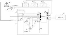
With reference to fig. 9, the solenoid valve control device 100 according to an embodiment of the present application is described below, where the solenoid valve control device 100 includes a signal conversion chip 110 and a power supply circuit 120, the power supply circuit 120 is connected to the solenoid valve 200 and the signal conversion chip 110, and the power supply circuit 120 is capable of supplying power to the solenoid valve 200 and the signal conversion chip 110. The pins 8 and 9 of the signal conversion chip 110 are connected to the system management module 300, and the signal conversion chip 110 can transmit signals (such as a liquid leakage digital signal and a control signal) with the system management module 300 through the pins 8 and 9.
The power supply circuit 120 includes a power supply module 124, a voltage converter 125, a transistor 126, and a transistor 127. The transistor 126 has one terminal connected to the solenoid valve 200 via the detection resistor 130, the other terminal connected to the pin 5 of the signal conversion chip 110 via the voltage converter 125, and the other terminal connected to a connection line between the transistor 127 and the power supply module 124. The power supply module 124 may supply power to the solenoid valve 200 and the signal conversion chip 110.
Three terminals of the transistor 127 are connected to ground, the power supply module 124, and pin 5 of the signal conversion chip 110, respectively. The signal conversion chip 110 controls the transistor 127 through the pin 5, and further controls the state of the transistor 126, so as to control the power supply module 124 to supply or cut off power to the solenoid valve 200.
Pin 4 of the signal conversion chip 110 is connected to any one of the detection coils 400 to obtain a leakage analog signal. Pin 7 of the signal conversion chip 110 is connected to both the coil 410 and the coil 420, and detects a voltage difference between the coil 410 and the coil 420 in the detection coil 400.
Pin 1 of the signal conversion chip 110 may be connected to two ends of the detection resistor 130 through the voltage comparator 140 to obtain a voltage of the detection resistor 130, where the voltage of the detection resistor 130 may indicate a supply current for the power supply circuit 120 to supply the solenoid valve 200.
Pin 2 of the signal conversion chip 110 may be connected to a power supply line between the solenoid valve 200 and the power supply circuit 120, the connection point is D, and the obtained power supply voltage for supplying power to the solenoid valve 200 by the power supply circuit 120 is obtained by detecting a voltage at the connection point D.
The pin 3 of the signal conversion chip 110 is connected to a temperature sensor 501 provided on the component 1, a temperature sensor 502 provided on the component 2, and a temperature sensor 503 provided on the component 3, respectively, to acquire the temperatures on the component 1, the component 2, and the component 3. Wherein, the component 1, the component 2 and the component 3 are components which need to be cooled in the equipment.
In the solenoid valve detecting device 100 shown in fig. 9, the signal conversion chip 110 receives the leakage analog signal from the detection coil 400 through the pin 4, converts the leakage analog signal into a leakage digital signal, and sends the leakage digital signal to the system management module 300 through the pins 8 and 9. The system management module 300 recognizes the liquid leakage digital signal, generates a control signal according to the liquid leakage digital signal, and sends the control signal to the signal conversion chip 110 through the pin 8 and the pin 9, the signal conversion chip 110 converts the control signal into a high level or a low level, and controls the state of the transistor 127 (e.g., the voltage at the connection point of the transistor 127 and the transistor 126) through the pin 5, and the state of the transistor 127 affects the state of the transistor 126, so as to control whether the power supply module 124 supplies power to the solenoid valve 200.
The signal conversion chip 110 obtains the voltage difference between the coil 410 and the coil 420 in the detection coil 400 through the pin 7, converts the voltage difference into a digital signal, and sends the digital signal to the system management module 300, so that the system management module 300 can determine whether the detection coil 400 works normally according to the digital signal.
The signal conversion chip 110 obtains the supply current for the electromagnetic valve 200 supplied by the power supply circuit 120 through the pin 1, obtains the supply voltage for the electromagnetic valve 200 supplied by the power supply circuit 120 through the pin 2, converts the supply current and the supply voltage for the electromagnetic valve 200 supplied by the power supply circuit 120 into corresponding digital signals, and sends the digital signals to the system management module 300.
The signal conversion chip 110 obtains the temperatures of the components 1, 2 and 3 through the pin 3, converts the temperatures into corresponding digital signals, and transmits the digital signals to the system management module 300 to determine the temperatures of the components 1, 2 and 3 according to the digital signals, so as to determine whether the cooling liquid is circulated in the cooling liquid radiating pipe.
It should be noted that the examples provided in this application are only illustrative. It will be apparent to those skilled in the art that, for convenience and brevity of description, the description of the various embodiments has been focused on, and for parts of one embodiment that are not described in detail, reference may be made to the description of other embodiments. The features disclosed in the embodiments of the invention, in the claims and in the drawings may be present independently or in combination. Features described in hardware in embodiments of the invention may be implemented by software and vice versa. And are not limited herein.
Claims (10)
1. An electromagnetic valve control device, which is used for controlling an electromagnetic valve on a cooling liquid radiating pipe in equipment, and comprises:
the power supply circuit is used for supplying power to the electromagnetic valve;
The signal conversion chip is connected with the power supply circuit and is used for:
receiving a liquid leakage analog signal, converting the liquid leakage analog signal into a liquid leakage digital signal, and sending the liquid leakage digital signal to a system management module, wherein the liquid leakage analog signal is used for indicating the liquid leakage of a cooling liquid radiating pipe in the equipment; the system management module is an external device of the electromagnetic valve control device and is coupled with the signal conversion chip;
after receiving a control signal from the system management module, controlling the power supply state of the power supply circuit to the electromagnetic valve according to the control signal, and further controlling the electromagnetic valve to block the circulation of the cooling liquid in the cooling liquid radiating pipe;
and detecting the temperature of the component needing heat dissipation in the equipment through a temperature sensor arranged on the component needing heat dissipation in the equipment.
2. The device of claim 1, wherein the signal conversion chip is further configured to detect a supply voltage of the power supply circuit for supplying power to the solenoid valve;
the signal conversion chip is further used for converting the power supply voltage into a voltage digital signal and sending the voltage digital signal to the system management module.
3. The device of claim 1 or 2, wherein the signal conversion chip is further configured to detect a supply current supplied by the power supply circuit to the solenoid valve;
the signal conversion chip is further used for converting the power supply current into a current digital signal and sending the current digital signal to the system management module.
4. The apparatus of claim 2, wherein the signal conversion chip comprises a first pin, the first pin connecting a power supply line between the power supply circuit and the solenoid valve;
the signal conversion chip is also used for detecting the power supply voltage supplied by the power supply circuit to the electromagnetic valve, and comprises:
the signal conversion chip determines the power supply voltage of the power supply circuit for supplying power to the electromagnetic valve through the first pin.
5. The apparatus of claim 3, wherein the signal conversion chip includes a second pin, the second pin is connected to two ends of a detection resistor through a voltage comparator, and the detection resistor is located on a power supply line between the power supply circuit and the solenoid valve;
the signal conversion chip is also used for detecting the power supply current supplied by the power supply circuit to the electromagnetic valve, and comprises:
And the signal conversion chip determines the power supply current supplied by the power supply circuit to the electromagnetic valve through the second pin.
6. The device according to any one of claims 1 to 5, further comprising a voltage converter, wherein the voltage converter is connected with the power supply circuit and the signal conversion chip,
the power supply circuit is also used for supplying power to the signal conversion chip through the voltage converter;
and the voltage converter is used for reducing the power supply voltage of the power supply circuit for supplying power to the signal conversion chip.
7. The device according to any one of claims 1 to 6, wherein when the power supply circuit supplies power to the solenoid valve, the solenoid valve is in an open state, and when the power supply circuit disconnects power to the solenoid valve, the solenoid valve is in a closed state.
8. The apparatus of any one of claims 1 to 6, wherein the signal conversion chip is a protocol conversion chip.
9. The device according to any one of claims 1 to 6, further comprising a detection coil for detecting whether the cooling liquid radiating pipe in the equipment leaks or not; the signal conversion chip acquires the leakage analog signal from the detection coil;
The detection coil comprises a first coil and a second coil which are connected in parallel, and the signal conversion chip is further used for detecting the voltage difference of the first coil and the second coil.
10. A signal conversion chip for implementing the functions of any one of claims 1 to 9.
Priority Applications (1)
| Application Number | Priority Date | Filing Date | Title |
|---|---|---|---|
| CN202210283006.9A CN114893606A (en) | 2019-09-09 | 2019-09-09 | Electromagnetic valve control device |
Applications Claiming Priority (2)
| Application Number | Priority Date | Filing Date | Title |
|---|---|---|---|
| CN202210283006.9A CN114893606A (en) | 2019-09-09 | 2019-09-09 | Electromagnetic valve control device |
| CN201910849817.9A CN110657274B (en) | 2019-09-09 | 2019-09-09 | Electromagnetic valve control device |
Related Parent Applications (1)
| Application Number | Title | Priority Date | Filing Date |
|---|---|---|---|
| CN201910849817.9A Division CN110657274B (en) | 2019-09-09 | 2019-09-09 | Electromagnetic valve control device |
Publications (1)
| Publication Number | Publication Date |
|---|---|
| CN114893606A true CN114893606A (en) | 2022-08-12 |
Family
ID=69038045
Family Applications (2)
| Application Number | Title | Priority Date | Filing Date |
|---|---|---|---|
| CN202210283006.9A Pending CN114893606A (en) | 2019-09-09 | 2019-09-09 | Electromagnetic valve control device |
| CN201910849817.9A Active CN110657274B (en) | 2019-09-09 | 2019-09-09 | Electromagnetic valve control device |
Family Applications After (1)
| Application Number | Title | Priority Date | Filing Date |
|---|---|---|---|
| CN201910849817.9A Active CN110657274B (en) | 2019-09-09 | 2019-09-09 | Electromagnetic valve control device |
Country Status (2)
| Country | Link |
|---|---|
| CN (2) | CN114893606A (en) |
| WO (1) | WO2021047442A1 (en) |
Families Citing this family (2)
| Publication number | Priority date | Publication date | Assignee | Title |
|---|---|---|---|---|
| CN114893606A (en) * | 2019-09-09 | 2022-08-12 | 超聚变数字技术有限公司 | Electromagnetic valve control device |
| CN114294465B (en) * | 2021-12-31 | 2024-04-30 | 富奥汽车零部件股份有限公司 | Pressure regulating control device and pressure regulating control method for electromagnetic valve |
Family Cites Families (7)
| Publication number | Priority date | Publication date | Assignee | Title |
|---|---|---|---|---|
| JPH10176768A (en) * | 1996-11-27 | 1998-06-30 | Xerox Corp | Microdevice supporting system and array of microdevice |
| US7262967B2 (en) * | 2005-06-29 | 2007-08-28 | Intel Corporation | Systems for low cost coaxial liquid cooling |
| CN102221651B (en) * | 2011-03-11 | 2015-05-27 | 太原理工大学 | Fault on-line diagnosis and early warning method of flameproof dry-type transformer for mine |
| CN104750210A (en) * | 2013-12-31 | 2015-07-01 | 鸿富锦精密工业(深圳)有限公司 | Server system |
| CN204176842U (en) * | 2014-07-25 | 2015-02-25 | 北京国电恒嘉科贸有限公司 | Data machine room air-conditioning system |
| CN108856975B (en) * | 2018-07-30 | 2020-08-14 | 西南交通大学 | Intelligent water-cooling electric arc additive manufacturing device and method for reducing heat accumulation of accumulation layer |
| CN114893606A (en) * | 2019-09-09 | 2022-08-12 | 超聚变数字技术有限公司 | Electromagnetic valve control device |
-
2019
- 2019-09-09 CN CN202210283006.9A patent/CN114893606A/en active Pending
- 2019-09-09 CN CN201910849817.9A patent/CN110657274B/en active Active
-
2020
- 2020-09-03 WO PCT/CN2020/113337 patent/WO2021047442A1/en active Application Filing
Also Published As
| Publication number | Publication date |
|---|---|
| CN110657274A (en) | 2020-01-07 |
| CN110657274B (en) | 2022-07-12 |
| WO2021047442A1 (en) | 2021-03-18 |
Similar Documents
| Publication | Publication Date | Title |
|---|---|---|
| CN110657274B (en) | Electromagnetic valve control device | |
| WO2021120735A1 (en) | Detection apparatus and server | |
| CN103973085B (en) | System and method for drive circuit | |
| CN104954145A (en) | Method for power over Ethernet, power sourcing equipment and system for power over Ethernet | |
| EP3669197B1 (en) | System and method for diagnosing electrical faults | |
| CN104216497A (en) | Power supply fault detection device and method | |
| CN111366316A (en) | System and method for detecting liquid in server and server | |
| CN111397819B (en) | Server cooling liquid leakage detection system and method and readable storage medium | |
| US11512860B2 (en) | Protection circuit and air conditioner | |
| JPWO2017149625A1 (en) | Relay board and sensor device | |
| CN104362582B (en) | Prevent the treating method and apparatus that circuit board burns | |
| US20230014670A1 (en) | Leakage detection apparatus and method and cabinet system | |
| US20120200417A1 (en) | Self-diagnosis method and system of wireless data service device | |
| CN110958002A (en) | Solid state power switching device | |
| CN110221677B (en) | Processor and electronic equipment | |
| US11175710B2 (en) | Ethernet power distribution systems, controllers, and methods | |
| CN220711308U (en) | Charging control chip and charging control circuit | |
| CN207947794U (en) | A kind of plug-and-play circuit, board and communication equipment | |
| US11542885B2 (en) | Load drive circuit and load drive system | |
| TWI777367B (en) | Liquid-cooled charging equipment with multiple charging connectors and method of operating the same | |
| CN220273314U (en) | Battery protection circuit, battery protection system and power supply equipment | |
| CN117148937A (en) | Board card heat dissipation method and system, storage medium and electronic equipment | |
| CN116193805A (en) | Dual-refrigerating system control architecture and dual-refrigerating system control method | |
| JP2024000586A (en) | Electronic control apparatus | |
| JP2006209618A (en) | Digital output device and diagnosing method using digital output device |
Legal Events
| Date | Code | Title | Description |
|---|---|---|---|
| PB01 | Publication | ||
| PB01 | Publication | ||
| SE01 | Entry into force of request for substantive examination | ||
| SE01 | Entry into force of request for substantive examination |