CN114888372A - Machining device and method for cooling hole on mounting edge of low-vortex guider - Google Patents
Machining device and method for cooling hole on mounting edge of low-vortex guider Download PDFInfo
- Publication number
- CN114888372A CN114888372A CN202210753139.8A CN202210753139A CN114888372A CN 114888372 A CN114888372 A CN 114888372A CN 202210753139 A CN202210753139 A CN 202210753139A CN 114888372 A CN114888372 A CN 114888372A
- Authority
- CN
- China
- Prior art keywords
- machining
- low
- cooling hole
- positioning pin
- guider
- Prior art date
- Legal status (The legal status is an assumption and is not a legal conclusion. Google has not performed a legal analysis and makes no representation as to the accuracy of the status listed.)
- Granted
Links
Images


Classifications
-
- B—PERFORMING OPERATIONS; TRANSPORTING
- B23—MACHINE TOOLS; METAL-WORKING NOT OTHERWISE PROVIDED FOR
- B23H—WORKING OF METAL BY THE ACTION OF A HIGH CONCENTRATION OF ELECTRIC CURRENT ON A WORKPIECE USING AN ELECTRODE WHICH TAKES THE PLACE OF A TOOL; SUCH WORKING COMBINED WITH OTHER FORMS OF WORKING OF METAL
- B23H1/00—Electrical discharge machining, i.e. removing metal with a series of rapidly recurring electrical discharges between an electrode and a workpiece in the presence of a fluid dielectric
-
- B—PERFORMING OPERATIONS; TRANSPORTING
- B23—MACHINE TOOLS; METAL-WORKING NOT OTHERWISE PROVIDED FOR
- B23H—WORKING OF METAL BY THE ACTION OF A HIGH CONCENTRATION OF ELECTRIC CURRENT ON A WORKPIECE USING AN ELECTRODE WHICH TAKES THE PLACE OF A TOOL; SUCH WORKING COMBINED WITH OTHER FORMS OF WORKING OF METAL
- B23H11/00—Auxiliary apparatus or details, not otherwise provided for
-
- Y—GENERAL TAGGING OF NEW TECHNOLOGICAL DEVELOPMENTS; GENERAL TAGGING OF CROSS-SECTIONAL TECHNOLOGIES SPANNING OVER SEVERAL SECTIONS OF THE IPC; TECHNICAL SUBJECTS COVERED BY FORMER USPC CROSS-REFERENCE ART COLLECTIONS [XRACs] AND DIGESTS
- Y02—TECHNOLOGIES OR APPLICATIONS FOR MITIGATION OR ADAPTATION AGAINST CLIMATE CHANGE
- Y02T—CLIMATE CHANGE MITIGATION TECHNOLOGIES RELATED TO TRANSPORTATION
- Y02T50/00—Aeronautics or air transport
- Y02T50/60—Efficient propulsion technologies, e.g. for aircraft
Landscapes
- Engineering & Computer Science (AREA)
- Mechanical Engineering (AREA)
- Electrical Discharge Machining, Electrochemical Machining, And Combined Machining (AREA)
Abstract
The invention relates to the technical field of machining of aviation engine guides, in particular to a device and a method for machining a cooling hole at the mounting edge of a low-vortex guide. According to the machining device for the cooling hole at the mounting edge of the low-vortex guider, the guider is quickly positioned by arranging the clamp arranged axially, the clamp is simple and easy to disassemble and install, the guider can be quickly aligned after being installed, and the design method of the device can be used for reference for the electrical machining of the ring-shaped piece.
Description
Technical Field
The invention relates to the technical field of machining of aero-engine deflectors, in particular to a device and a method for machining a cooling hole on a mounting edge of a low-vortex deflector.
Background
The thrust is increased for the effective circulation of low pressure turbine director air current to novel aeroengine at present, all designs the crowd's hole of evenly distributed on the installation limit of director, and these crowd's holes are complicated space angle unanimous with guide vane's direction, need process on six electric spark machine tools, because the director size is great, the director frock is more complicated, be unfavorable for the dismantlement, consequently need design a simple light processingequipment can make the quick alignment of director.
The guider is high in cost, long in manufacturing period and free of test pieces, an effective program simulation method is designed before the small holes on the edge are machined by electric sparks to verify that the angle and the size are not wrong, and the situation that parts are scrapped due to damage and incorrect size in machining is avoided.
Disclosure of Invention
Aiming at the problems in the prior art, the invention provides a device and a method for machining a cooling hole on a mounting edge of a low-vortex guider.
The invention is realized by the following technical scheme:
the utility model provides a processingequipment of low vortex director installation limit cooling hole, includes a plurality of anchor clamps that set up along processing equipment chassis circumference, anchor clamps are placed on the equipment chassis, anchor clamps include installation piece, first locating pin and second locating pin set up respectively in the top and the bottom of installation piece, first locating pin is tangent with the second radial positioning size phi B of director, the second locating pin is tangent with equipment chassis external diameter phi A.
Preferably, the clamp is provided with at least three clamps
Preferably, the mounting block, the first positioning pin and the second positioning pin are integrally formed.
Preferably, the first positioning pin and the second positioning pin are detachably connected with the mounting block.
Preferably, the first positioning pin is detachably connected with the guide.
Preferably, the second positioning pin is detachably connected with the equipment chassis.
Preferably, the bottom of the mounting block is provided with a positioning strip, and the positioning strip is matched with a clamping groove on the equipment chassis.
A processing method of a cooling hole at the installation edge of a low-vortex guider adopts a processing device of the cooling hole at the installation edge of the low-vortex guider, and comprises the following steps:
s1, mounting a plurality of clamps; the first positioning pin is tangent to the guider in the radial direction, and the second positioning pin is tangent to the outer diameter of the equipment chassis;
s2, aligning and checking the equipment;
and S3, punching according to the machining thickness of the guide.
Preferably, in S2, a cross check method is used for the verification.
Preferably, in S3, when punching, one hole is punched every 1 ° rotation.
Compared with the prior art, the invention has the following beneficial effects:
according to the machining device for the cooling hole at the mounting edge of the low-vortex guider, the guider is quickly positioned by arranging the clamp arranged axially, the clamp is simple and easy to disassemble and install, the guider can be quickly aligned after being installed, and the design method of the device can be used for reference for the electrical machining of the ring-shaped piece.
According to the machining method of the cooling hole on the mounting edge of the low-pressure turbine guider, a cross calibration method is adopted before parts are machined, and the low-pressure turbine guider is prevented from being scrapped due to size out-of-tolerance in the machining process.
Drawings
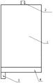
FIG. 1 is a front view of a clamp construction;
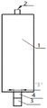
FIG. 2 is a left side view of the clamp structure;
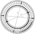
FIG. 3 is a top view of the clamp device construction;
FIG. 4 is a top view of the clamp mounted on the equipment chassis;
FIG. 5 is a top view of the low vortex pilot;
FIG. 6 is a diagrammatic view of the clamp attached to the machine tool and the low pressure guide;
FIG. 7 is a schematic view of the A-axis electrode tangent to the guide mounting edge;
fig. 8 is a schematic diagram of the verification process.
In the figure, 1, a mounting block; 2. a first positioning pin; 3. a second positioning pin; 4. a positioning bar; 5. an equipment chassis; 6. a card slot; 7. a guide device.
Detailed Description
The present invention will now be described in further detail with reference to specific examples, which are intended to be illustrative, but not limiting, of the invention.
The invention discloses a machining device for a cooling hole on a mounting edge of a low-vortex guider, which comprises a plurality of clamps arranged along the circumferential direction of a machining equipment chassis, wherein the number of the clamps is at least three.
The fixture comprises an installation block 1, a first positioning pin 2 and a second positioning pin 3, wherein the first positioning pin 2 and the second positioning pin 3 are respectively arranged at the top and the bottom of the installation block 1, the first positioning pin 2 is tangent to a second radial positioning size phi B of the guider 7, the second positioning pin 3 is tangent to an outer diameter phi A of the equipment chassis 5, namely, the distance A between the first positioning pin 2 and the second positioning pin 3 is phi A-phi B.
The bottom of the mounting block is provided with a positioning strip 4, referring to fig. 4, 5 and 6, the positioning strip is matched with a clamping groove 6 on an equipment chassis 5, and the width of the positioning strip 4 and the equipment clamping groove is B.
Example 1
The mounting block 1, the first positioning pin 2 and the second positioning pin 3 are integrally formed.
Example 2
First locating pin 2 and second locating pin 3 all can dismantle with installation piece 1 and be connected. The first positioning pin 2 is detachably connected with the guide 7. The second positioning pin 3 is detachably connected with the equipment chassis 3.
A processing method of a cooling hole at the installation edge of a low-vortex guider adopts a processing device of the cooling hole at the installation edge of the low-vortex guider, and comprises the following steps:
s1, mounting a plurality of clamps with reference to fig. 6 and 7; the first positioning pin 2 is tangent to the guider 7 in the radial direction, and the second positioning pin is tangent to the outer diameter of the equipment chassis;
s2, aligning the device and performing verification by using a cross verification method, referring to fig. 8, the method specifically includes:
(1) after alignment, rotating the A (with a tool electrode) axis and the B axis of the machine tool by 90 degrees, enabling the Y axis to return to zero, moving the X axis to visually observe the installation edge of the guider 7, moving the Y axis back and forth, enabling the A axis electrode (with the electrode size of phi E) to be tangent to the installation edge phi C of the guider 7, confirming whether Y axis return to zero is displayed or not, and observing the A axis electrode and the installation edge phi C of the guider 7 to confirm the tangency in the process of rotating the C axis by 360 degrees, wherein the A axis electrode and the installation edge phi C of the guider 7 are shown in figure 7;
(2) then, the X axis is moved to ensure that the moving distance of the A axis electrode to the inside of the guider 7 is as follows: phi C-phi D + phi E/2mm, namely the radial size phi Dmm of the position of the air film hole of the mounting edge;
(3) after the A, B, X, Z axis is reset to zero, the B axis is rotated 20 degrees, the a axis is rotated 45 degrees, the X, Z axis is moved to move the electrode to the Φ D position, and finally the C axis is rotated 4 times by 90 degrees to form 360 degrees, and the electrode is confirmed to be on Φ C in the rotating process to form a cross checking method, as shown in fig. 8, note that: the moving process goes to the Y axis to be motionless.
And S3, punching according to the machining thickness of the guide, and punching one hole for every 1-degree rotation.
The above-mentioned embodiments are only preferred embodiments of the present invention, and are not intended to limit the technical solution of the present invention, and it should be understood by those skilled in the art that the technical solution can be modified and replaced by a plurality of simple modifications and replacements without departing from the spirit and principle of the present invention, and the modifications and replacements also fall into the protection scope covered by the claims.
Claims (10)
1. The machining device for the cooling hole in the installation edge of the low-vortex guider is characterized by comprising a plurality of clamps arranged along the circumferential direction of a machining equipment chassis, wherein the clamps are placed on the equipment chassis and comprise an installation block, a first positioning pin and a second positioning pin, the first positioning pin and the second positioning pin are respectively arranged at the top and the bottom of the installation block, the first positioning pin is tangent to a second radial positioning size phi B of the guider, and the second positioning pin is tangent to an outer diameter phi A of the equipment chassis.
2. The apparatus for machining a low-vortex finder mounting edge cooling hole according to claim 1, wherein there are at least three clamps.
3. The machining device for the low vortex finder mounting edge cooling hole according to claim 1, wherein the mounting block, the first locating pin and the second locating pin are integrally formed.
4. The machining device for the low vortex finder mounting edge cooling hole according to claim 1, wherein the first locating pin and the second locating pin are both detachably connected to the mounting block.
5. The apparatus for machining a low-swirl deflector-mounted edge cooling hole as claimed in claim 1, wherein the first locator pin is detachably connected to the deflector.
6. The apparatus of claim 1, wherein the second locating pin is removably attached to the equipment chassis.
7. The machining device for the cooling hole of the mounting edge of the low vortex finder as claimed in claim 1, wherein a positioning strip is provided at the bottom of the mounting block, and the positioning strip is engaged with a slot on a chassis of the device.
8. A method for machining a cooling hole on a mounting side of a low-swirl vane machine, which uses the device for machining a cooling hole on a mounting side of a low-swirl vane machine according to any one of claims 1 to 7, comprising the steps of:
s1, mounting a plurality of clamps; the first positioning pin is tangent to the guider in the radial direction, and the second positioning pin is tangent to the outer diameter of the equipment chassis;
s2, aligning and checking the equipment;
and S3, punching according to the machining thickness of the guide.
9. The apparatus for machining a low vortex finder mounting edge cooling hole according to claim 8, wherein in S2, a cross check method is used for the check.
10. The apparatus for machining a low vortex finder mounting edge cooling hole according to claim 8, wherein in S3, when the hole is punched, one hole is punched for every 1 ° rotation.
Priority Applications (1)
| Application Number | Priority Date | Filing Date | Title |
|---|---|---|---|
| CN202210753139.8A CN114888372B (en) | 2022-06-29 | 2022-06-29 | Machining device and method for cooling holes on installation edge of low-vortex guider |
Applications Claiming Priority (1)
| Application Number | Priority Date | Filing Date | Title |
|---|---|---|---|
| CN202210753139.8A CN114888372B (en) | 2022-06-29 | 2022-06-29 | Machining device and method for cooling holes on installation edge of low-vortex guider |
Publications (2)
| Publication Number | Publication Date |
|---|---|
| CN114888372A true CN114888372A (en) | 2022-08-12 |
| CN114888372B CN114888372B (en) | 2023-09-12 |
Family
ID=82730034
Family Applications (1)
| Application Number | Title | Priority Date | Filing Date |
|---|---|---|---|
| CN202210753139.8A Active CN114888372B (en) | 2022-06-29 | 2022-06-29 | Machining device and method for cooling holes on installation edge of low-vortex guider |
Country Status (1)
| Country | Link |
|---|---|
| CN (1) | CN114888372B (en) |
Citations (5)
| Publication number | Priority date | Publication date | Assignee | Title |
|---|---|---|---|---|
| US6371468B1 (en) * | 1999-12-17 | 2002-04-16 | United Technologies Research Center | Universal workpiece holder |
| CN204621124U (en) * | 2015-03-17 | 2015-09-09 | 瑞麦(宁波)机械设计制造有限公司 | A kind of clipping chuck of split being suitable for annular workpieces |
| CN106181477A (en) * | 2016-08-16 | 2016-12-07 | 中航湖南通用航空发动机有限公司 | The processing method of special-shaped groove between a kind of assembling clamp and stator blade |
| CN213827086U (en) * | 2020-11-04 | 2021-07-30 | 浙江省军工集团有限公司 | Positioning fixture for processing end face of annular disc part |
| CN214922445U (en) * | 2021-05-06 | 2021-11-30 | 大连恒基数控机床有限公司 | Special clamp for oil baffle ring products |
-
2022
- 2022-06-29 CN CN202210753139.8A patent/CN114888372B/en active Active
Patent Citations (5)
| Publication number | Priority date | Publication date | Assignee | Title |
|---|---|---|---|---|
| US6371468B1 (en) * | 1999-12-17 | 2002-04-16 | United Technologies Research Center | Universal workpiece holder |
| CN204621124U (en) * | 2015-03-17 | 2015-09-09 | 瑞麦(宁波)机械设计制造有限公司 | A kind of clipping chuck of split being suitable for annular workpieces |
| CN106181477A (en) * | 2016-08-16 | 2016-12-07 | 中航湖南通用航空发动机有限公司 | The processing method of special-shaped groove between a kind of assembling clamp and stator blade |
| CN213827086U (en) * | 2020-11-04 | 2021-07-30 | 浙江省军工集团有限公司 | Positioning fixture for processing end face of annular disc part |
| CN214922445U (en) * | 2021-05-06 | 2021-11-30 | 大连恒基数控机床有限公司 | Special clamp for oil baffle ring products |
Non-Patent Citations (1)
| Title |
|---|
| 王德新 等: "外环块数控电火花加工工艺研究", 电加工与模具, no. 05, pages 57 - 60 * |
Also Published As
| Publication number | Publication date |
|---|---|
| CN114888372B (en) | 2023-09-12 |
Similar Documents
| Publication | Publication Date | Title |
|---|---|---|
| EP2439008B1 (en) | Method and apparatus for machining a shroud block | |
| US10227874B2 (en) | Tooling fixture assembly for processing a component of a gas turbine engine | |
| EP2093641B1 (en) | Performing a process on a workpiece | |
| KR101280154B1 (en) | Method and apparatus for inspecting turbine nozzle segments | |
| CN102699724B (en) | Machining tooling fixture for welding joint tensile sample and clamping and positioning method for machining tooling fixture | |
| CN114888372A (en) | Machining device and method for cooling hole on mounting edge of low-vortex guider | |
| CN108857296B (en) | Device and method for combined machining of split casing and stationary blade ring | |
| CN107991082B (en) | Combined machining method for bearing mounting hole of aero-engine casing assembly | |
| GB2550855B (en) | Method of manufacture | |
| EP2969281B1 (en) | Process and apparatus to restore distorted features on gas turbine vanes | |
| CN216989960U (en) | Machining tool for testing hole of rectifier blade of interstage casing of aero-engine | |
| EP3192606B1 (en) | Electrical discharge machining apparatus and method | |
| CN114310376A (en) | Machining device for hollow blade of aero-engine | |
| CN209321288U (en) | A kind of dynamic dispenser primary blades degree of impairment detection instrument | |
| CN112139774A (en) | Engine precision casting blade and processing method thereof | |
| CN212601380U (en) | Positioning tool | |
| CN110657727A (en) | Measuring tool and method for detecting hole position deviation | |
| CN117226198A (en) | Device and method for machining thermal stress relief groove of turbine guider of aero-engine | |
| CN210587732U (en) | High-precision fool-proof positioning jig of laser marking machine | |
| CN109398750B (en) | Tool and method for detecting damage condition of main blade of power diffuser | |
| CN219561691U (en) | Auxiliary device for processing blade trailing edge air film hole | |
| CN112059658B (en) | Machining tool and machining method for multi-cavity product | |
| CN111843081B (en) | Turbine blade exhaust edge air film hole machining method | |
| CN213163518U (en) | Quick positioning jig for circular workpiece for linear cutting | |
| CN220561359U (en) | Quick dull and stereotyped location frock |
Legal Events
| Date | Code | Title | Description |
|---|---|---|---|
| PB01 | Publication | ||
| PB01 | Publication | ||
| SE01 | Entry into force of request for substantive examination | ||
| SE01 | Entry into force of request for substantive examination | ||
| GR01 | Patent grant | ||
| GR01 | Patent grant |