CN1148515C - Arrangement relating to mechanically interlocking devices - Google Patents
Arrangement relating to mechanically interlocking devices Download PDFInfo
- Publication number
- CN1148515C CN1148515C CNB998048690A CN99804869A CN1148515C CN 1148515 C CN1148515 C CN 1148515C CN B998048690 A CNB998048690 A CN B998048690A CN 99804869 A CN99804869 A CN 99804869A CN 1148515 C CN1148515 C CN 1148515C
- Authority
- CN
- China
- Prior art keywords
- locking
- unit
- releasing unit
- elastic component
- plunger
- Prior art date
- Legal status (The legal status is an assumption and is not a legal conclusion. Google has not performed a legal analysis and makes no representation as to the accuracy of the status listed.)
- Expired - Lifetime
Links
Images


Classifications
-
- E—FIXED CONSTRUCTIONS
- E05—LOCKS; KEYS; WINDOW OR DOOR FITTINGS; SAFES
- E05C—BOLTS OR FASTENING DEVICES FOR WINGS, SPECIALLY FOR DOORS OR WINDOWS
- E05C19/00—Other devices specially designed for securing wings, e.g. with suction cups
- E05C19/06—Other devices specially designed for securing wings, e.g. with suction cups in which the securing part if formed or carried by a spring and moves only by distortion of the spring, e.g. snaps
-
- H—ELECTRICITY
- H04—ELECTRIC COMMUNICATION TECHNIQUE
- H04M—TELEPHONIC COMMUNICATION
- H04M1/00—Substation equipment, e.g. for use by subscribers
- H04M1/02—Constructional features of telephone sets
- H04M1/0202—Portable telephone sets, e.g. cordless phones, mobile phones or bar type handsets
- H04M1/0206—Portable telephones comprising a plurality of mechanically joined movable body parts, e.g. hinged housings
- H04M1/0208—Portable telephones comprising a plurality of mechanically joined movable body parts, e.g. hinged housings characterized by the relative motions of the body parts
- H04M1/021—Portable telephones comprising a plurality of mechanically joined movable body parts, e.g. hinged housings characterized by the relative motions of the body parts using combined folding and rotation motions
-
- H—ELECTRICITY
- H04—ELECTRIC COMMUNICATION TECHNIQUE
- H04M—TELEPHONIC COMMUNICATION
- H04M1/00—Substation equipment, e.g. for use by subscribers
- H04M1/02—Constructional features of telephone sets
- H04M1/0202—Portable telephone sets, e.g. cordless phones, mobile phones or bar type handsets
- H04M1/0249—Details of the mechanical connection between the housing parts or relating to the method of assembly
- H04M1/0252—Details of the mechanical connection between the housing parts or relating to the method of assembly by means of a snap-on mechanism
Landscapes
- Engineering & Computer Science (AREA)
- Mechanical Engineering (AREA)
- Signal Processing (AREA)
- Telephone Set Structure (AREA)
- Lock And Its Accessories (AREA)
- Transmitters (AREA)
- Mobile Radio Communication Systems (AREA)
- Snaps, Bayonet Connections, Set Pins, And Snap Rings (AREA)
Abstract
It is shown a locking arrangement at a portable device such as a telephone terminal. The device comprises a main body (303) and a movable protruding member such as a flip-lid. The protruding member is switchable between at least a first position and a second position with respect to the main body. The locking arrangement comprises a plunger unit (305) and a lock and release unit (300) with a fixed part (301) and a resilient part (302). The resilient part (302) is resilient along at least one direction of resilience (X) away from the fixed part (301). The plunger unit (305) is switchable, along a direction of insertion and retraction, between a disengaged position and an engaged position between the fixed part (301) and the resilient part (302).
Description
Technical field
The present invention relates to two device for mechanical interlocking mechanical locking frameworks are particularly comprised a plunger unit locking framework of locking and releasing unit.
Background technique
Mobile telephone terminal field is the technological progress of feature with weight and size, has arrived the stage that must consider outward appearance.The size restrictions of previous generation mobile terminal device is that the size of battery pack is controlled by the size of terminal equipment components and parts to a certain extent.On the other hand, the terminal equipment in the modern times of being made up of a small amount of highly integrated low energy consumption circuit is easy to put in the unit of hand size.In fact recently the terminal equipment size of development is to make the distance between loudspeaker and the MIC microphone become an important design parameter so for a short time.In order further to make the terminal equipment miniaturization, still keep between loudspeaker/MIC microphone simultaneously and suitable location between user's ear/mouth, mechanical solution is very general as the foldable lid or the folding arm that comprise MIC microphone or loudspeaker.
The hand-held terminal of being furnished with folding and overturn cover, in fact, any have the protruding element that is connected through the hinge and problem that can folding handheld devices all can run between device main shell diverse location is that individual part locking and the individual part that how to realize protruding element opened.
U. S. Patent (No.5327584) has disclosed the example of this respect situation in the prior art, and it has shown a mobile phone with lid opening mechanism.Constituted the lid opening mechanism by a plurality of individual part co-operation, it comprises the mating part that have the hole, the latch by functional unit work and be fixed on wire spring on the stopper.Need not say more, only comprise the fact of a plurality of parts according to it, this mechanism on installing and making with regard to more complicated.
The visible UK Patent Application of another example (GB-2106977) of locking framework.The ornamental shell that comprises socket and lid has socket and lid engagement mechanism, realizes engagement and unclamp to rely between two elastic lock tongues applying power.An elastic lock tongue is positioned at cover plate, and one is positioned at socket, and power applies through independent sliding element.
Summary of the invention
The problem that the present invention prepares to solve is that the once action locking that how to realize the elongator as overturn cover of portable communication device is opened with once moving.The problem that the present invention also prepares to solve is how to utilize minimum component to realize that action of one hand of outer extension member locks and singlehanded action is opened.
Target of the present invention is to overcome above-mentioned problem.In brief, by a locking framework is provided, it has realized above-mentioned target by the plunger unit that can engage and break away from the locking of being made up of elastic component and fixed block and open the unit.
At length say, proposed a kind of locking framework of handheld devices.This device comprises a main body and a mobilizable protruding element.This protruding element can be opened closure between at least one primary importance relevant with main body and a second place.Locking framework comprises a plunger unit, a locking and a releasing unit that has elastic component and fixed block.Elastic component along at least one direction bullet from fixed block.Plunger unit is along fixed block and disengaging position elastic component between and the engagement interdigit conversion of the direction that enters and return at locking and releasing unit.
An advantage of the present invention is that in order to open elongator from device main body, plunger unit engages and goes out of lock only needs a user's of the present invention hand little trick with releasing unit.
Another advantage of the present invention is, can make and assemble the complexity and expensive being reduced of this device with the actual conditions of a motion action according to locking and releasing unit.
Description of drawings
Fig. 1 a-c shows two schematic side view of first embodiment of locking framework, a sectional view;
Fig. 2 a-c shows a schematic side view and two sectional views of second embodiment of locking framework;
Fig. 3 shows the 3rd embodiment's of locking framework schematic side view;
Fig. 4 shows the 4th embodiment's of locking framework schematic side view;
Fig. 5 shows the perspective diagram of the mobile phone that has rotatable cover;
Fig. 6 a-c shows the schematic side view of three width of cloth plunger unit;
Fig. 7 a-b shows the perspective diagram of two lockings that are connected with crust of the device and releasing unit.
Embodiment
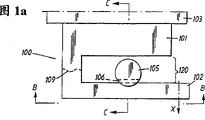
First preferred embodiment of locking framework according to the present invention, Fig. 1 a, Fig. 1 b and Fig. 1 c have shown the general function that element 104 is locked onto main body 103.This mechanism comprises locking and a releasing unit 100 and a plunger 105.
First side view as shown in Figure 1a, locking and releasing unit 100 are connected to main body 103.The concrete structure of main body 103 does not belong to scope of the present invention, although typical main body 103 can be further below illustrational handheld devices as phone.Also have, the mode that locking and releasing device 100 are connected to main body 103 does not belong to scope of the present invention yet, and the details among therefore relevant Fig. 1 a-c can further not explained.
Locking and releasing device 100 comprise the elongated fixed block 101 that is connected to main body 103 and elongated elastic component 102.Elastic component 102 101 flicks along direction x from fixed block, has caused the gap 120 with the excursion between fixed block and elastic component 101 and 102.
The line 109 that defines shown in the figure is for the elastic component 102 and the fixed block 101 mutual transition of locking wherein and releasing unit are described roughly.Defining line 109 is not to be used for illustrating that where element 101 and 102 is connected to each other, but hints the necessity of two independent components.Defining line 109 would rather be the simple expression of a fact, and promptly the form of locking and releasing unit 100 can be a unit, and is made up of two separate piece that connect together.
The elasticity of elastic component 102 reality is the performances according to the elastic component material, as physical property, obtains.Can know how to obtain suitable elastic performance from prior art.Therefore needn't be gone through.But clearly plastic material is a reasonably selection by injection-molded manufactured.Yet whether other material such as metal even timber are fit to depend on the condition of application.
With reference to figure 1b and Fig. 1 c, there is the elongated plunger unit 105 of notch 106 and tapered head 107 to be connected with element 104.Element 104 is to lock onto with main body 103 by the locking framework of being made up of plunger unit 105 and locking and releasing unit 100.Example with element 104 of property will be discussed below in conjunction with other embodiments of the invention.
The space 120 of plunger unit 105 between elastic component 102 and fixed block 101 in Fig. 1 a-c, locking member 104 is to main body 103.The realization of locking is by move the plunger 105 that has the head that is tapered along direction Y, along direction X compressing elastic component 102, makes elastic component 102 increase space 120 until notch 106 and elastic component 102 engagements along direction X, and at this moment elastic component is return with the X opposite direction.Notch 106 has an inclined-plane 108, and elastic component slides along this limit when returning.Direction X is substantially perpendicular to direction Y.This also is other embodiment's of a back of the present invention situation.
By forcing the element 104 with engagement plunger 105 to retreat along direction Y, element 104 can be thrown off from main body 103.This return motion must cause elastic component 102 to slide along the inclined-plane 108 of notch 106, causes elastic component 102 towards the directions X motion, widens space 120 along directions X.Element 104 and plunger 105 further retreat and will cause plunger to be thrown off from locking and releasing unit 100.
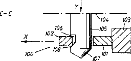
Fig. 2 a-c shows according to second embodiment of the present invention.As the example of front, locking and the releasing unit 200 be made up of fixed block 201 and elastic component 202 are connected to main body as handheld devices.In a typical actual example, main body 203 may be a mobile telephone terminal.In this case, main body 203 is equivalent to the shell of this telephone terminal.
Fixed block 201 and elastic component 202 all are elongated and form one single that dot and dash line 209 is represented the position of the transition zone between two elements 201 and 202 roughly.Elastic component 202 201 flicks the space 220 that is formed with constant interval along direction X from fixed block.Elastic component 201 is connected to driving member 212, or best and integral body of its formation.Driving member 212 extends by the hole on the main body 203 213, makes it can be approaching from the outside.
Shown in preceding example, the elongated plunger unit 205 with the notch 206 and the end 207 that is tapered is connected to an element 204.Element 204 will be connected to main body 203 by the locking framework of being made up of plunger unit 205 and locking and releasing unit 200.The typical case of element 204 can be the rotatable cover of mobile telephone terminal.The space 220 of plunger unit 205 between elastic component 202 and fixed block 201, locking member 204 is to main body 203.
As the embodiment shown in Fig. 1 a-c, locking and release are by along Y direction mobile plunger 205, oppress elastic component 202 and strengthen the inclined-plane 211 of space 220 until the notch 210 of notch 206 engagement elastic components 201 along directions X.The notch 206 of plunger also has an inclined-plane 208, and elastic component 202 slides along the inclined-plane when returning.
Have the element 204 that meshes plunger 205 and break away from main body by applying Y direction pulling force backward.The motion backward that this power causes will make the inclined-plane 208 of inclined-plane 211 relative notches 206 of the notch 210 of elastic component 202 slide, and therefore cause elastic component 202 to move towards directions X, widen space 220.The continuation return motion of element 204 and plunger 205 will cause plunger 205 to go out of lock and releasing unit 200.From locked position plunger is discharged size and the physical property that required pulling force is decided by relevant part certainly.Apply a power for simultaneously elastic component 202 along directions X and help to break away from action.This power can apply by driving member 212.In fact, all can help lock out action and break away from action by applying power for driving member 212 along directions X.
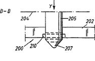
The embodiment who in Fig. 3, has schematically shown next locking framework.As the example of front, fixed block 301 and main body 303 such as the shell of telephone terminal, connect.Fixed block 301 carries out the transition to elastic component 302 in the position of representing with dot and dash line 309.Elastic component 302 is along the directions X resilience and can rely on driving member 312 effects to leave the origin-location forward and backward along directions X.Driving member 312 forms the part of pusher arm end, and pusher arm is connected along the directions X elongation and with elastic component 302.Pusher arm 314 extends by the hole 303 of main body, and the mode with precedent is identical substantially.
Fig. 3 has also shown the plunger 305 that has notch 306, and it can be engaged to locked position and the position that goes out of lock as shown in the previous example.
Also have the example 400 of a locking framework in Fig. 4, schematically to illustrate.Fixed block 401 is connected to main body 403.Fixed block 401 carries out the transition to can be along the elastic component 402 of directions X resilience.Space 420 between fixed block 401 and elastic component 402 is plunger 405 present positions that have notch 406.This example only illustrates and has difform part, for example the rectangular cross-section of plunger 405 as seen from the figure.
Fig. 5, Fig. 6 a-c and Fig. 7 a-b show the other selected embodiment of the present invention.Mobile telephone terminal 500 has comprised that form is the main body of shell 503 and is connected with rotatable cover 520.Know that from prior art terminal comprises the device that is used for the communication network conversation, is furnished with display device 524 within shell 503, keyboard 525, loudspeaker 523 and the MIC microphone on rotatable cover.
Rotatable cover 520 can turn to the closed position of overlay keyboard 525 by linkage 521 from an open position around axle R.Though do not show in Fig. 5, opposite shell 503 was given and is covered 520 spring-loading mechanisms when linkage 521 can comprise closed position.Fig. 5 has shown the rotatable cover 520 that is shown in an open position.
For lid being engaged and disengaging is closed and open position respectively.Terminal 500 comprises according to locking framework of the present invention.Plunger unit 505 is connected to hub cap 520, and locking and releasing unit (in Fig. 7 a 700) are connected to the inboard of shell.Hole 513 on shell 503 allows plungers 505 to enter locking and releasing unit (among Fig. 7 a 700).
Fig. 6 a-c shows the profile of three width of cloth plungers 605, the plunger 505 that analogy is connected with rotatable cover 520 as shown in Figure 5.Plunger has the head that diminishes gradually 607 and with the notch 606 on inclined-plane 608, generally speaking with earlier examples in plunger 105 and 205 identical shape is arranged.Although shown plunger 605 is independent components that are not connected with any rotatable cover, know that all plunger 605 can be integrated with rotatable cover (520 among Fig. 5).
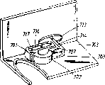
Fig. 7 a and Fig. 7 b have shown the details of locking and releasing unit 700, and locking and releasing unit are connected to the inboard of the shell 703 of the shell 503 that is equivalent among Fig. 5, comprise that a fixed block 701, one elastic components 702 and have the pusher arm 714 of driving member 712.Similar to the example of front, when power acts on driving member 712 along directions X, elastic component 702 leaves fixed block 701 along rebound direction X, and two spaces 720 between the element are increased.Fixed block 701 by outstanding shell 703 knob 717 be connected to the inboard of shell 703, knob also engages with fixed block 701 by opening 716.
Plunger (as 505 among Fig. 5,605 among Fig. 6 a-c) with tapered head 707 adopts the notch 708 with the same way as engagement elastic component 702 disclosed in the top example.Apply power along directions X protruding in shell 703 and pass on the driving member 712 in hole 713, the space is increased, plunger is thrown off from position engaged.
Top example has shown enforcement of the present invention, and wherein plunger is connected to an overhanging element, and locking and releasing unit are connected to device main body.But other embodiment wherein plunger is connected to main body and locks that to be connected to overhanging element with releasing unit undoubtedly also be feasible.
Claims (29)
1. the locking framework of handheld devices, described mechanism comprises a main body (103,203,303,403,503,703) and a mobilizable protruding element (104,204,520), described elongator (104,204,520) with main body (103,203,303,403,503,703) opening and closing between relevant at least one primary importance and the second place, described locking framework comprises plunger unit (105,205,305,405,505,605) and locking and releasing unit (100,200,300,400,700);
Described locking and releasing unit (100,200,300,400,700) comprise a fixed block (101,201,301,401,701) and elastic component (102,202,302,402,702);
Described elastic component (1 02,202,302,402,702) has at least one to leave the rebound direction (X) of fixed block (101,201,301,401,701);
Described plunger unit (105,205,305,405,505,605) along entering and return direction (Y) at locking and releasing unit (100,200,300,400,700) fixed block (101,201,301,401,701) and elastic component (102,202, change between engaging position 302,402,702) and disengaging configuration;
It is characterized in that locking and releasing unit (100,200,300,400,700) comprise that also driving member (212,312,712) is used to make elastic component (102,202,302,402,702) along rebound direction (X) action, this direction substantially with enter vertical with exit axis (Y).
2. locking framework as claimed in claim 1 is characterized in that, described plunger unit (105,205,305,405,505,605) be connected to described protruding element (104,204,520), described locking and releasing unit (100,200,300,400,700) by described fixed block (101,201,301,401,701) be connected to the described main body (103,203 of device, 303,403,503,703).
3. locking framework as claimed in claim 1 is characterized in that, described plunger unit (105,205,305,405,505,605) be connected to the described main body (103 of device, 203,303,403,503,703), described locking and releasing unit (100,200,300,400,700) by described fixed block (101,201,301,401,701) be connected to described protruding element (104,204,520).
4. as any one locking framework in the claim 1~3, it is characterized in that, one pusher arm (314,714) extend and be connected to described elastic component (102 along described rebound direction (X), 202,302,402,702), by helping lock out action in the described rebound direction in described pusher arm upper edge (X) power of applying or throwing off action.
5. locking framework as claimed in claim 4 is characterized in that, described driving member (212,312,712) has constituted the extension device of the described elastic component (102,202,302,402,702) of described locking and releasing unit (100,200,300,400,700).
6. locking framework as claimed in claim 1 is characterized in that, the form of described locking and releasing unit (100,200,300,400,700) is single unit.
7. locking framework as claimed in claim 1 is characterized in that, the form of described locking and releasing unit (100,200,300,400,700) is that at least two independent components combine.
8. locking framework as claimed in claim 1 is characterized in that, described locking and releasing unit (100,200,300,400,700) described elastic component (102,202,302,402,702) and described fixed block (101,201,301,401,701) all be elongated shape, connect together in an end separately.
9. locking framework as claimed in claim 1 is characterized in that, described plunger unit (105,205,305,405,505,605) tapered head (107,207 is arranged, 607,707), when described plunger unit (105,205,305,405,505,605) insert described engaging position along entering and return direction (Y), make described locking and releasing unit (100,200,300,400,700) described elastic component (102,202,302,402,702) break away from described fixed block (101,201 easily, 301,401,701).
10. locking framework as claimed in claim 1 is characterized in that, described plunger unit (105,205,305,405,505,605) has notch (106,206,306,406,606), and plunger unit (105,205,305,405,505,605) is locked in the engaging position.
11. the locking framework as claim 10 is characterized in that, described notch (106,206,306,406,606) includes inclined-plane (108,208,308).
12. the locking framework as claim 10 or 11 is characterized in that, described locking and releasing unit (100,200,300,400,700) have notch (210,310,710), in described engaging position and described plunger notch (106,206,306,406,606) engagement.
13. the locking framework as claim 12 is characterized in that, the described notch (210,310,710) of described locking and releasing unit (100,200,300,400,700) comprises inclined-plane (211,708).
14. the locking framework as claim 12 is characterized in that, the described notch (210,310,710) of described locking and releasing unit (100,200,300,400,700) is positioned at described elastic component (102,202,302,402,702).
15. portable communication device, it comprises a main body (103,203,303,403,503,703) and a rotatable cover (104,204,520), described rotatable cover is connected to described main body ((103,203,303 with hinge-unit (521), 403,503,703), described rotatable cover (104,204,520) with described main body (103,203,303,403,503,703) opening and closing between relevant at least one primary importance and the second place, described device also comprises a locking framework, it comprises a plunger unit (105,205,305,405,505,605) and locking and releasing unit (100,200,300,400,700), it is characterized in that
Described locking and releasing unit (100,200,300,400,700) comprise fixed block (101,201,301,401,701) and elastic component (102,202,302,402,702);
Described elastic component (102,202,302,402,702) leaves at least one rebound direction (X) of fixed block (101,201,301,401,701);
Described plunger unit (105,205,305,405,505,605) along entering and return direction (Y) at locking and releasing unit (100,200,300,400,700) fixed block (101,201,301,401,701) and elastic component (102,202, be connected or throw off between the engaging position 302,402,702) and disengaging configuration;
It is characterized in that described locking and releasing unit (100,200,300,400,700) comprise that also driving member (212,312,712) is used to make elastic component (102,202,302,402,702) along rebound direction (X) action, this direction substantially with enter vertical with exit axis (Y).
16. the portable communication device as claim 15 is characterized in that, described plunger unit (105,205,305,405,505,605) be connected to described protruding element (104,204,520), described locking and releasing unit (100,200,300,400,700) by described fixed block (101,201,301,401,701) be connected to the described main body (103,203 of device, 303,403,503,703).
17. the portable communication device as claim 15 is characterized in that, described plunger unit (105,205,305,405,505,605) be connected to the described main body (103 of device, 203,303,403,503,703), described locking and releasing unit (100,200,300,400,700) by described fixed block (101,201,301,401,701) be connected to described protruding element (104,204,520).
18. as any one portable communication device in the claim 15~17, it is characterized in that, one pusher arm (314,714) extend and be connected to described elastic component (102 along described rebound direction (X), 202,302,402,702), by helping lock out action in the described rebound direction in described pusher arm upper edge (X) power of applying or throwing off action.
19. the portable communication device as claim 18 is characterized in that, described driving member (212,312,712) has constituted the extension device of the described elastic component (102,202,302,402,702) of described locking and releasing unit (100,200,300,400,700).
20. the portable communication device as claim 15 is characterized in that, the form of described locking and releasing unit (100,200,300,400,700) is independent unit.
21. the portable communication device as claim 15 is characterized in that, the form of described locking and releasing unit (100,200,300,400,700) is that at least two independent components combine.
22. the portable communication device as claim 15 is characterized in that, described locking and releasing unit (100,200,300,400,700) described elastic component (102,202,302,402,702) and described fixed block (101,201,301,401,701) all be elongated shape, connect together in an end separately.
23. the portable communication device as claim 15 is characterized in that, described plunger unit (105,205,305,405,505,605) tapered head (107,207 is arranged, 607,707), when described plunger unit (105,205,305,405,505,605) insert described engaging position along entering and return direction (Y), make described locking and releasing unit (100,200,300,400,700) described elastic component (102,202,302,402,702) break away from described fixed block (101,201 easily, 301,401,701).
24. the portable communication device as claim 15 is characterized in that, described plunger unit (105,205,305,405,505,605) notch (106,206,306,406,606) is arranged, plunger unit (105,205,305,405,505,605) is locked in the engaging position.
25. the portable communication device as claim 24 is characterized in that, described notch (106,206,306,406,606) includes an inclined-plane (108,208,308).
26. the portable communication device as claim 24 or 25 is characterized in that, described locking and releasing unit (100,200,300,400,700) notch (210,310,710) is arranged, at described engaging position and described plunger notch (106,206,306,406,606) engagement.
27. the portable communication device as claim 26 is characterized in that, the described notch (210,310,710) of described locking and releasing unit (100,200,300,400,700) comprises inclined-plane (211,708).
28. the portable communication device as claim 26 is characterized in that, the described notch (210,310,710) of described locking and releasing unit (100,200,300,400,700) is positioned at described elastic component (102,202,302,402,702).
29. the portable communication device as claim 15 is characterized in that, described locking and releasing unit (100,200,300,400,700) be connected to described shell (103,203,303,403,503,703) internal surface is positioned at described shell (103,203,303,403,503,703) hole on (213,313,513,713) next door, when when described disengaged position is transformed into described engaging position, described hole allows described plunger (105,205,305,405,505,605) enter.
Applications Claiming Priority (2)
| Application Number | Priority Date | Filing Date | Title |
|---|---|---|---|
| SE98012214 | 1998-04-07 | ||
| SE9801221A SE511860C2 (en) | 1998-04-07 | 1998-04-07 | Locking mechanism for mechanical interconnection of two devices and portable communication device provided with such locking mechanism |
Publications (2)
| Publication Number | Publication Date |
|---|---|
| CN1296553A CN1296553A (en) | 2001-05-23 |
| CN1148515C true CN1148515C (en) | 2004-05-05 |
Family
ID=20410886
Family Applications (1)
| Application Number | Title | Priority Date | Filing Date |
|---|---|---|---|
| CNB998048690A Expired - Lifetime CN1148515C (en) | 1998-04-07 | 1999-04-06 | Arrangement relating to mechanically interlocking devices |
Country Status (16)
| Country | Link |
|---|---|
| US (1) | US6363243B1 (en) |
| EP (1) | EP1070205B1 (en) |
| JP (1) | JP4391688B2 (en) |
| KR (1) | KR20010042460A (en) |
| CN (1) | CN1148515C (en) |
| AR (1) | AR015267A1 (en) |
| AU (1) | AU756891B2 (en) |
| BR (1) | BR9909466A (en) |
| CO (1) | CO5021174A1 (en) |
| DE (1) | DE69918282T2 (en) |
| EE (1) | EE04251B1 (en) |
| HK (1) | HK1035220A1 (en) |
| MY (1) | MY124326A (en) |
| SE (1) | SE511860C2 (en) |
| TR (1) | TR200002861T2 (en) |
| WO (1) | WO1999051885A1 (en) |
Families Citing this family (5)
| Publication number | Priority date | Publication date | Assignee | Title |
|---|---|---|---|---|
| JP2001251400A (en) * | 2000-03-03 | 2001-09-14 | Matsushita Electric Ind Co Ltd | Mobile phone |
| US7003333B2 (en) * | 2002-09-17 | 2006-02-21 | Motorola, Inc. | Latch mechanism and electronic device employing a latch mechanism |
| JP4703982B2 (en) * | 2004-07-15 | 2011-06-15 | パナソニック株式会社 | Portable electronic devices |
| CN201123002Y (en) * | 2007-07-11 | 2008-09-24 | 招家荣 | Portable carrying device |
| CN105593512B (en) * | 2013-10-01 | 2018-12-04 | 恩普乐斯股份有限公司 | The mounting structure of fuel injection device nozzle plate |
Family Cites Families (12)
| Publication number | Priority date | Publication date | Assignee | Title |
|---|---|---|---|---|
| JPS586070U (en) * | 1981-07-03 | 1983-01-14 | 北川工業株式会社 | wire clamp |
| GB2106977B (en) * | 1981-09-10 | 1985-02-13 | Yoshida Industry Co | Vanity case |
| SE441261B (en) * | 1984-03-26 | 1985-09-23 | Jan Ingemar Neslund | PASKLEMMA |
| JPH04281628A (en) * | 1991-03-11 | 1992-10-07 | Matsushita Electric Ind Co Ltd | Portable radio equipment |
| US5274882A (en) * | 1992-03-03 | 1994-01-04 | Ericsson Ge Mobile Communications Inc. | Hinge mechanism |
| JP2689913B2 (en) * | 1994-07-15 | 1997-12-10 | 日本電気株式会社 | Automatic open type folding portable radio |
| JP2658906B2 (en) * | 1994-09-22 | 1997-09-30 | 日本電気株式会社 | Automatic open folding mobile phone |
| FI99070C (en) * | 1995-06-30 | 1997-09-25 | Nokia Mobile Phones Ltd | Position |
| SE507149C2 (en) * | 1996-08-29 | 1998-04-06 | Ericsson Telefon Ab L M | Hinge device |
| US5956398A (en) * | 1997-07-11 | 1999-09-21 | Ericsson Inc. | Telephone switching mechanism |
| US6151486A (en) * | 1998-10-30 | 2000-11-21 | Ericsson Inc. | Magnetic latch and release device and radiotelephones incorporating same |
| KR100621606B1 (en) * | 1998-12-03 | 2006-11-30 | 삼성전자주식회사 | A portable computer |
-
1998
- 1998-04-07 SE SE9801221A patent/SE511860C2/en not_active IP Right Cessation
-
1999
- 1999-04-06 EP EP99921335A patent/EP1070205B1/en not_active Expired - Lifetime
- 1999-04-06 JP JP2000542581A patent/JP4391688B2/en not_active Expired - Lifetime
- 1999-04-06 EE EEP200000572A patent/EE04251B1/en unknown
- 1999-04-06 CN CNB998048690A patent/CN1148515C/en not_active Expired - Lifetime
- 1999-04-06 BR BR9909466-5A patent/BR9909466A/en not_active IP Right Cessation
- 1999-04-06 KR KR1020007011072A patent/KR20010042460A/en not_active Application Discontinuation
- 1999-04-06 TR TR2000/02861T patent/TR200002861T2/en unknown
- 1999-04-06 MY MYPI99001304A patent/MY124326A/en unknown
- 1999-04-06 AU AU38574/99A patent/AU756891B2/en not_active Expired
- 1999-04-06 WO PCT/SE1999/000560 patent/WO1999051885A1/en not_active Application Discontinuation
- 1999-04-06 DE DE69918282T patent/DE69918282T2/en not_active Expired - Lifetime
- 1999-04-07 US US09/287,971 patent/US6363243B1/en not_active Expired - Lifetime
- 1999-04-07 CO CO99020330A patent/CO5021174A1/en unknown
- 1999-04-07 AR ARP990101581A patent/AR015267A1/en active IP Right Grant
-
2001
- 2001-11-09 HK HK01107894A patent/HK1035220A1/en not_active IP Right Cessation
Also Published As
| Publication number | Publication date |
|---|---|
| EP1070205B1 (en) | 2004-06-23 |
| SE9801221D0 (en) | 1998-04-07 |
| WO1999051885A1 (en) | 1999-10-14 |
| CO5021174A1 (en) | 2001-03-27 |
| US6363243B1 (en) | 2002-03-26 |
| CN1296553A (en) | 2001-05-23 |
| JP2002510778A (en) | 2002-04-09 |
| AU756891B2 (en) | 2003-01-23 |
| BR9909466A (en) | 2000-12-19 |
| SE9801221L (en) | 1999-10-08 |
| JP4391688B2 (en) | 2009-12-24 |
| EE04251B1 (en) | 2004-02-16 |
| DE69918282D1 (en) | 2004-07-29 |
| AR015267A1 (en) | 2001-04-18 |
| TR200002861T2 (en) | 2001-01-22 |
| SE511860C2 (en) | 1999-12-06 |
| KR20010042460A (en) | 2001-05-25 |
| EP1070205A1 (en) | 2001-01-24 |
| DE69918282T2 (en) | 2005-07-28 |
| AU3857499A (en) | 1999-10-25 |
| EE200000572A (en) | 2002-04-15 |
| MY124326A (en) | 2006-06-30 |
| HK1035220A1 (en) | 2001-11-16 |
Similar Documents
| Publication | Publication Date | Title |
|---|---|---|
| US7991444B2 (en) | Slide mechanism for slide-type portable terminal devices | |
| US8160661B2 (en) | Slide mechanism for slide-type portable terminal devices | |
| CN1874667A (en) | Structure of sliding closure, and portable electronic equipment of using the structure of sliding closure | |
| KR100735304B1 (en) | Sliding device for mobile phone | |
| EP1906631A2 (en) | Semi-automatic sliding device for a portable terminal and portable terminal having the same | |
| CN1148515C (en) | Arrangement relating to mechanically interlocking devices | |
| US7369884B2 (en) | Slide assembly | |
| CN1197328C (en) | Folding communication device | |
| CN113489823B (en) | Electronic equipment | |
| CN1713804A (en) | Latch mechanism | |
| CN109933141B (en) | Functional assembly, electronic device and control method thereof | |
| JPWO2008035441A1 (en) | Mobile device | |
| KR100689498B1 (en) | Sliding module for sliding type mobile phone | |
| KR100678039B1 (en) | Camera door opening and shutting apparatus for folder type mobile phone | |
| KR200338957Y1 (en) | Sliding Mudule for Sliding Cellphone | |
| KR200395863Y1 (en) | Push-Push type mobile communication terminal | |
| JP2008079292A (en) | Portable terminal | |
| WO2008105969A1 (en) | Magnetic hinge mechanism for wireless communication devices | |
| KR20000014986A (en) | Cover switch for flip type radio telephone | |
| KR100678265B1 (en) | Semi-automatic swing device for mobile phone | |
| CN1794750A (en) | Slide type portable device having an optical zoom assembly | |
| US20240319474A1 (en) | Lens device | |
| CN1199543C (en) | Pivot set | |
| CN220569107U (en) | Electronic equipment | |
| CN2706972Y (en) | Mobile phone |
Legal Events
| Date | Code | Title | Description |
|---|---|---|---|
| C06 | Publication | ||
| PB01 | Publication | ||
| C10 | Entry into substantive examination | ||
| SE01 | Entry into force of request for substantive examination | ||
| C14 | Grant of patent or utility model | ||
| GR01 | Patent grant | ||
| CX01 | Expiry of patent term |
Granted publication date: 20040505 |
|
| CX01 | Expiry of patent term |