CN114833375A - Rotatable tubular metal resonator puncher - Google Patents
Rotatable tubular metal resonator puncher Download PDFInfo
- Publication number
- CN114833375A CN114833375A CN202210566539.8A CN202210566539A CN114833375A CN 114833375 A CN114833375 A CN 114833375A CN 202210566539 A CN202210566539 A CN 202210566539A CN 114833375 A CN114833375 A CN 114833375A
- Authority
- CN
- China
- Prior art keywords
- clamping
- base
- fixing
- longitudinal
- assembly
- Prior art date
- Legal status (The legal status is an assumption and is not a legal conclusion. Google has not performed a legal analysis and makes no representation as to the accuracy of the status listed.)
- Withdrawn
Links
Images
Classifications
-
- B—PERFORMING OPERATIONS; TRANSPORTING
- B23—MACHINE TOOLS; METAL-WORKING NOT OTHERWISE PROVIDED FOR
- B23B—TURNING; BORING
- B23B41/00—Boring or drilling machines or devices specially adapted for particular work; Accessories specially adapted therefor
-
- B—PERFORMING OPERATIONS; TRANSPORTING
- B23—MACHINE TOOLS; METAL-WORKING NOT OTHERWISE PROVIDED FOR
- B23B—TURNING; BORING
- B23B47/00—Constructional features of components specially designed for boring or drilling machines; Accessories therefor
-
- B—PERFORMING OPERATIONS; TRANSPORTING
- B23—MACHINE TOOLS; METAL-WORKING NOT OTHERWISE PROVIDED FOR
- B23Q—DETAILS, COMPONENTS, OR ACCESSORIES FOR MACHINE TOOLS, e.g. ARRANGEMENTS FOR COPYING OR CONTROLLING; MACHINE TOOLS IN GENERAL CHARACTERISED BY THE CONSTRUCTION OF PARTICULAR DETAILS OR COMPONENTS; COMBINATIONS OR ASSOCIATIONS OF METAL-WORKING MACHINES, NOT DIRECTED TO A PARTICULAR RESULT
- B23Q3/00—Devices holding, supporting, or positioning work or tools, of a kind normally removable from the machine
- B23Q3/02—Devices holding, supporting, or positioning work or tools, of a kind normally removable from the machine for mounting on a work-table, tool-slide, or analogous part
- B23Q3/06—Work-clamping means
- B23Q3/062—Work-clamping means adapted for holding workpieces having a special form or being made from a special material
- B23Q3/065—Work-clamping means adapted for holding workpieces having a special form or being made from a special material for holding workpieces being specially deformable, e.g. made from thin-walled or elastic material
-
- B—PERFORMING OPERATIONS; TRANSPORTING
- B23—MACHINE TOOLS; METAL-WORKING NOT OTHERWISE PROVIDED FOR
- B23Q—DETAILS, COMPONENTS, OR ACCESSORIES FOR MACHINE TOOLS, e.g. ARRANGEMENTS FOR COPYING OR CONTROLLING; MACHINE TOOLS IN GENERAL CHARACTERISED BY THE CONSTRUCTION OF PARTICULAR DETAILS OR COMPONENTS; COMBINATIONS OR ASSOCIATIONS OF METAL-WORKING MACHINES, NOT DIRECTED TO A PARTICULAR RESULT
- B23Q7/00—Arrangements for handling work specially combined with or arranged in, or specially adapted for use in connection with, machine tools, e.g. for conveying, loading, positioning, discharging, sorting
- B23Q7/02—Arrangements for handling work specially combined with or arranged in, or specially adapted for use in connection with, machine tools, e.g. for conveying, loading, positioning, discharging, sorting by means of drums or rotating tables or discs
-
- B—PERFORMING OPERATIONS; TRANSPORTING
- B23—MACHINE TOOLS; METAL-WORKING NOT OTHERWISE PROVIDED FOR
- B23Q—DETAILS, COMPONENTS, OR ACCESSORIES FOR MACHINE TOOLS, e.g. ARRANGEMENTS FOR COPYING OR CONTROLLING; MACHINE TOOLS IN GENERAL CHARACTERISED BY THE CONSTRUCTION OF PARTICULAR DETAILS OR COMPONENTS; COMBINATIONS OR ASSOCIATIONS OF METAL-WORKING MACHINES, NOT DIRECTED TO A PARTICULAR RESULT
- B23Q7/00—Arrangements for handling work specially combined with or arranged in, or specially adapted for use in connection with, machine tools, e.g. for conveying, loading, positioning, discharging, sorting
- B23Q7/04—Arrangements for handling work specially combined with or arranged in, or specially adapted for use in connection with, machine tools, e.g. for conveying, loading, positioning, discharging, sorting by means of grippers
-
- Y—GENERAL TAGGING OF NEW TECHNOLOGICAL DEVELOPMENTS; GENERAL TAGGING OF CROSS-SECTIONAL TECHNOLOGIES SPANNING OVER SEVERAL SECTIONS OF THE IPC; TECHNICAL SUBJECTS COVERED BY FORMER USPC CROSS-REFERENCE ART COLLECTIONS [XRACs] AND DIGESTS
- Y02—TECHNOLOGIES OR APPLICATIONS FOR MITIGATION OR ADAPTATION AGAINST CLIMATE CHANGE
- Y02P—CLIMATE CHANGE MITIGATION TECHNOLOGIES IN THE PRODUCTION OR PROCESSING OF GOODS
- Y02P70/00—Climate change mitigation technologies in the production process for final industrial or consumer products
- Y02P70/10—Greenhouse gas [GHG] capture, material saving, heat recovery or other energy efficient measures, e.g. motor control, characterised by manufacturing processes, e.g. for rolling metal or metal working
Landscapes
- Engineering & Computer Science (AREA)
- Mechanical Engineering (AREA)
- Drilling And Boring (AREA)
Abstract
The invention discloses a rotatable metal pipe perforating machine which comprises a base, a fixing clamping assembly, an opposite moving clamping assembly, a feeding and discharging assembly and a drilling machine main body, wherein the base is fixed at an operation station, the fixing clamping assembly is arranged on one side of a table top on the base, the opposite moving clamping assembly is arranged on the opposite position of the fixing clamping assembly, a longitudinal clamping block and a transverse clamping block which can be automatically clamped are arranged in the fixing clamping assembly and the opposite moving clamping assembly, the automatic clamping of an elliptical pipe can be realized, the opposite moving clamping assembly can be automatically adjusted according to the length of the elliptical pipe, the feeding and discharging assembly capable of being automatically clamped is further arranged at the front end of the table top on the base, and manual clamping is not needed.
Description
Technical Field
The invention relates to the field of metal punching, in particular to a rotatable metal punching machine.
Background
The conventional metal round hole punching can be realized by clamping a round pipe only by three claws, but the three claws cannot clamp unconventional pipes such as an elliptical pipe and the like, generally, a tool consistent with the outer wall of the elliptical pipe is manufactured for clamping and fixing, then the elliptical pipe is manually placed on a processing table board by the tool, the drilling is manually carried out by a drilling machine, the punching can only be carried out in the direction vertical to the processing table board, when a hole with a certain angle with the table board is processed, the hole is also processed by a rotary drilling machine head, the mode has the defects of poor punching precision and low efficiency, for example, an automatic rotatable punching machine disclosed by the prior art (CN 205380294U) comprises a base, a guide rail, a round angle square, a first fastening bolt, a second fastening bolt and a punching drill shaft, wherein the punching drill shaft comprises a drill bit, a rotating shaft, a small motor, an upper shell and a lower shell, the rear side of the upper shell is rotatably connected with the rear side of the upper end of the base through the first fastening bolt, one side of inferior valve is equipped with a vertical direction chi seam, and is equipped with the second fastening bolt on this chi seam, the fillet chi uses first fastening bolt as the centre of a circle, insert the chi seam, the edge of this fillet chi is equipped with a sliding seam, the second fastening bolt passes by this sliding seam, both ends card is equipped with a slide bar around the inside of base, the slide bar is isometric, its upper end is rotatable to be fixed on the bottom surface of small-size motor, the lower extreme and the sliding piece rotatable coupling of card setting in the guide rail for accomplish the regulation of drill spindle angle, open and estimate the eye and look round angle chi and adjust, this kind of regulation mode can only single adjustment drill bit angle, can't carry out corresponding fixed to the processing work piece, easily take place the skew, influence the precision of processing.
Disclosure of Invention
The invention discloses a rotatable metal pipe punching machine, which comprises a base, wherein two fixing and clamping assemblies are arranged on the base, one fixing and clamping assembly is fixedly arranged on the base, the other fixing and clamping assembly is slidably arranged on the base, two clamping assemblies are used for fixing a metal pipe more stably, and a feeding and discharging assembly and a drilling machine main body are also arranged on the base.
The fixed clamping assembly comprises: the metal pipe clamping device comprises a rotating mechanism, wherein the rotating mechanism is fixedly arranged on a base, a transverse fixing component and a longitudinal fixing component are arranged on the rotating mechanism, the rotating mechanism can process different positions of a metal pipe, an opposite moving clamping assembly is arranged on a fixing clamping assembly which is slidably arranged on the base, the opposite moving clamping assembly drives the fixing clamping assembly to slide, and the metal pipe clamping device can be used for clamping metal pipes with different lengths and different positions.
Further, rotary mechanism includes the mount, fixed mounting is in the fixed clamping assembly on the base, and mount fixed mounting is in on the base, the fixed rotatory cassette that is equipped with of mount terminal surface, rotatory cassette cavity rotate on the mount and are equipped with rotatory inner gear, are equipped with on the rotatory inner gear horizontal fixed subassembly and vertical fixed subassembly drive the tight tubular metal resonator of clamp and rotate together, rotate on the mount and are equipped with rotary drive gear, rotary drive gear drive rotatory inner gear rotates, uses the pinion to drive the gear wheel and increases the moment of torsion, rotates more stably.
Furthermore, the longitudinal fixing assembly comprises two longitudinal clamping blocks, one end of each longitudinal clamping block is inserted into the corresponding rotary clamping seat in a sliding mode from top to bottom, a longitudinal clamping block rack is fixedly mounted at the other end of each longitudinal clamping block, toothed parts of the upper longitudinal clamping block rack and the lower longitudinal clamping block rack are opposite, a longitudinal clamping gear is meshed between the two longitudinal clamping block racks, a power element is arranged on the longitudinal clamping gear and drives the longitudinal clamping gear to drive the two longitudinal clamping block racks, and clamping and loosening of the two fixing blocks are driven by a driving element to improve efficiency.
Furthermore, the transverse fixing device comprises two transverse clamping blocks, two transverse clamping blocks are arranged, one end of each transverse clamping block is inserted into each of two sides of the rotary clamping seat in a sliding mode, a transverse clamping rack is fixedly installed at the other end of each transverse clamping block, toothed parts of the two transverse clamping racks are installed oppositely, a transverse clamping gear is meshed between the two transverse clamping racks, a power original piece is connected onto the transverse clamping gear and drives the longitudinal clamping gear to drive the two transverse clamping racks, and clamping and loosening of the two fixing blocks are driven by a driving piece to improve efficiency.
Furthermore, the base is provided with an opposite movement clamping sliding position, the fixing clamping assembly which is slidably mounted on the base is a fixing frame which is slidably mounted on the opposite movement clamping sliding position, the opposite movement clamping assembly comprises a moving sliding block which is slidably mounted at the bottom of the opposite movement clamping sliding position and is fixedly connected with the fixing frame, a threaded hole is formed in the center of the moving sliding block, a lead screw is matched in the threaded hole, the lead screw is rotatably mounted in the opposite movement clamping sliding position, the moving sliding block cannot rotate due to the matching with the bottom end when the lead screw moves, the moving sliding block moves relatively stably and is connected with a power device through the lead screw to drive the moving sliding block to move.
Further, go up the unloading assembly and include the jack catch base, jack catch base slidable mounting is in on the base, jack catch base bottom is connected with the lateral shifting device, rotates in the jack catch base and is equipped with the jack catch frame, and jack catch shelf location gripper snatchs the raw materials, and fixed jack catch frame rotating electrical machines that are equipped with in jack catch base side, jack catch frame rotating electrical machines pivot and jack catch frame fixed connection can realize one hundred eighty degrees rotations and conveniently get the material.
Further, the mechanical gripper comprises two jaw linkage gears, the jaw linkage gears are rotatably installed in the jaw frame, the two jaw linkage gears are meshed with each other, rear connecting rods are fixedly installed on the two jaw linkage gears, jaws are hinged on the rear connecting rods, arc plates are arranged at the tail ends of the jaws, a front connecting rod is hinged in the middle of each jaw, the front connecting rod is hinged with the jaw frame, two groups of clamping devices are arranged to be more stable according to the quadrilateral connecting rod principle, and one jaw linkage gear is connected with a power original to drive the whole mechanical gripper.
Further, arc grooves are formed in one ends of the two transverse clamping blocks and one ends of the two longitudinal clamping blocks in the rotary clamping seat.
Compared with the prior art, the invention has the beneficial effects that: (1) the fixed clamping assembly and the opposite moving clamping assembly are provided with two groups of longitudinal clamping blocks and two groups of transverse clamping blocks which are arranged aiming at different shapes of metal pipes, so that the fixed clamping assembly and the opposite moving clamping assembly are not only suitable for automatically clamping conventional circular pipes, but also can automatically clamp special pipes such as elliptical pipes, and the like, and have high automation degree and wider application range; (2) the main body rotating clamping seat for clamping the metal tube in the opposite-direction moving clamping assembly can automatically rotate, and can automatically adjust according to the processing of different angles, so that the processing precision is high; (3) the base is also provided with the feeding and discharging assembly capable of automatically clamping the metal pipe and automatically feeding, so that the feeding and discharging of the metal pipe can be automatically completed, and the processing efficiency is high.
Drawings
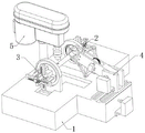
Fig. 1 is a schematic view of the overall structure of a rotatable metal pipe punch according to the present invention.
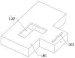
FIG. 2 is a schematic structural diagram of a base according to the present invention.
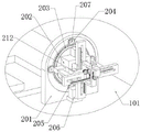
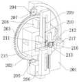
Fig. 3, 4 and 5 are schematic structural views of the fixing and clamping assembly of the invention.
FIG. 6 is a schematic structural view of the clamping assembly for moving in opposite directions according to the present invention.
Fig. 7 and 8 are schematic structural views of the feeding and discharging assembly of the present invention.
Detailed Description
The present invention will be further described with reference to specific examples, which are illustrative of the invention and are not to be construed as limiting the invention.
Example (b): a rotatable metal tube punch as shown in fig. 1, 2, 3, 4, 5, 6, 7, 8 comprising: the drilling machine comprises a base 1, fixed clamping assemblies 2, opposite moving clamping assemblies 3, a feeding and discharging assembly 4 and a drilling machine main body 5, wherein the drilling machine main body 5 and the feeding and discharging assembly 4 are oppositely arranged and are used for processing metal pipes on the fixed clamping assemblies 2, the base 1 comprises a bottom frame 101, the bottom frame 101 is provided with opposite moving clamping sliding positions 102 and a feeding and discharging sliding position 103 which are used for installing other parts, the base 1 is provided with two fixed clamping assemblies 2, a fixed frame 201 in one fixed clamping assembly 2 is fixedly arranged on the base 1, a circular through hole is formed in the middle of the fixed frame 201, an annular sliding groove is formed in the outer ring of the through hole, a rotating inner gear 203 is arranged in the annular sliding groove, a plurality of small circular holes are formed in the fixed frame 201 and are evenly distributed on the periphery of the rotating inner gear 203, the number of the fixed frame can be four, one of the rotating inner gear 203 is arranged on the upper side, the lower side and the left side and the right side, and the rotating drive gears 205 are arranged in the circular holes at the lower side, the rotary driving gear 205 is meshed with the rotary internal gear 203, the rotary driving gear 205 can be driven to rotate by a rotary driving motor 206, the rotary driving motor 206 is fixedly installed on the fixed frame 201, a rotating shaft of the rotary driving motor 206 is fixedly connected with the rotary driving gear 205 through a key shaft, rotary auxiliary gears 204 are rotatably installed in other small round holes through rotary auxiliary gear seats 207, and all the rotary auxiliary gears 204 are meshed with the rotary internal gear 203 to assist the rotation of the rotary internal gear 203.
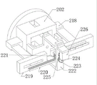
The end face of the internal rotating gear 203 is fixedly provided with a rotating clamping seat 202 through bolts, the rotating clamping seat 202 is provided with a large square through hole, the other four surfaces are provided with small through holes, the upper and lower through holes are all inserted with longitudinal clamping blocks 208, one end of each longitudinal clamping block 208 in the rotating clamping seat 202 is dug into an arc shape and is more suitable for the fixation of a metal pipe, the two through holes on the side face of the rotating clamping seat 202 are all inserted with transverse clamping blocks 218 in a sliding manner, one end of each transverse clamping block 218 in the rotating clamping seat 202 is also dug into an arc shape, the other ends of the two longitudinal clamping blocks 208 are all welded with longitudinal clamping block connecting plates 209, the two longitudinal clamping block connecting plates 209 are fixedly provided with longitudinal clamping block racks 210 through bolts, the upper and lower longitudinal clamping block racks 210 are installed in a staggered manner and have opposite toothed parts, a longitudinal clamping gear 211 is engaged between the two longitudinal clamping block racks 210, and a power device is arranged on the longitudinal clamping gear 211, the longitudinal clamping gear 211 can drive the two longitudinal clamping block racks 210 to simultaneously move towards the upper side and the lower side respectively or towards the middle, and then drive the two longitudinal clamping blocks 208 to clamp or loosen the metal pipe in the rotary clamping seat 202.
The power means driving the longitudinal clamping gear 211 may be: the rotating clamping seat 202 is fixedly provided with a longitudinal clamping support plate 212 through a bolt, the longitudinal clamping support plate 212 is provided with a through hole, a longitudinal clamping conversion shaft 215 is rotatably arranged in the through hole, two ends of the longitudinal clamping conversion shaft 215 are respectively and fixedly provided with a longitudinal clamping gear 211 and a longitudinal clamping conversion gear 213 through key shafts, the longitudinal clamping support plate 212 is fixedly provided with a longitudinal clamping driving motor 217, the longitudinal clamping driving motor 217 is fixedly provided with a longitudinal clamping driving gear 216 through a coupler, the longitudinal clamping driving gear 216 drives the longitudinal clamping conversion gear 213, and the longitudinal clamping conversion gear 213 drives the longitudinal clamping gear 211.
One end of each of the two transverse clamping blocks 218 is fixedly provided with a transverse clamping block connecting plate 219, each of the two transverse clamping block connecting plates 219 is fixedly provided with a transverse clamping rack 220 through a bolt, the transverse clamping racks 220 can be conveniently replaced by using the bolt, the two transverse clamping racks 220 are installed in a staggered mode and are opposite in toothed part, a transverse clamping gear 221 is rotatably arranged between the two transverse clamping racks 220, the transverse clamping gear 221 is meshed with the two transverse clamping racks 220, the longitudinal clamping gear 211 is connected with a power element to drive the two transverse clamping racks 220 to simultaneously move towards two sides or simultaneously move towards the middle, and then the two transverse clamping blocks 218 are driven to clamp or loosen a metal pipe in the rotary clamping seat 202.
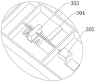
The opposite moving clamping assembly 3 comprises a moving slide block 303, a lead screw 304 and a lead screw motor 305, a sliding fixing clamping assembly 2 is arranged on the base 1 at a position opposite to the fixed fixing clamping assembly 2, a fixed frame 201 in the sliding fixing clamping assembly 2 is arranged in the opposite moving clamping sliding position 102 in a sliding manner and is connected with a moving slide block 303, the center of the moving slide block 303 is provided with a threaded through hole or a mounting nut, a screw rod 304 is rotatably arranged in the opposite moving clamping sliding position 102 and is matched with the moving slide block 303, one end of the screw rod 304 is connected with a screw rod motor 305, the screw rod motor 305 is a servo motor, the screw rod motor 305 is fixedly arranged in the opposite moving clamping sliding position 102, the shaft coupling and the lead screw 304 are fixedly installed, the lead screw motor 305 rotates to drive the rotary auxiliary gear 204 to rotate, and the lead screw 304 drives the movable sliding block 303 to drive the fixed frame 201, so that the whole fixed clamping assembly 2 slides in the opposite-direction movable clamping sliding position 102.
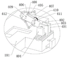
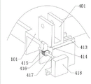
The loading and unloading assembly 4 comprises a jaw base 401, the jaw base 401 is slidably mounted in the loading and unloading sliding position 103, a jaw frame 402 is rotatably mounted on the jaw base 401 through a rotating shaft, the outer end of the jaw frame 402 is provided with a groove, two jaw linkage gears 410 are rotatably mounted in the groove and are meshed with each other, a rear connecting rod 407 is fixedly mounted on the jaw linkage gears 410 through bolts, one end of the rear connecting rod 407 is hinged with a jaw 405, the tail end of the jaw 405 is welded with an arc-shaped plate for grabbing a metal pipe, the middle position of the jaw 405 is hinged with a front connecting rod 406 through a connecting rod shaft 408, the front connecting rod 406 is hinged on the jaw frame 402 through a connecting rod connecting shaft 409, a jaw linkage motor 412 is fixed on the side surface of the jaw frame 402 through bolts, the jaw linkage motor 412 is selected as a servo motor, the jaw linkage motor 412 is fixedly connected with one of the jaw linkage gears 410 through a jaw linkage gear shaft 411, and the jaw linkage motor 412 rotates to drive the connecting rods to rotate, the tail ends of the two clamping jaws 405 can clamp or loosen a steel pipe, the side face of the clamping jaw base 401 is fixedly provided with a clamping jaw frame rotating motor 404 through a bolt, the clamping jaw frame rotating motor 404 is a servo motor, the clamping jaw frame rotating motor 404 is fixedly connected with a clamping jaw frame 402 through a clamping jaw frame rotating shaft 403, and the clamping jaw frame rotating motor 404 drives the clamping jaw frame 402 to rotate the lower end of the clamping jaw base 401 and is provided with a transverse moving device to meet the requirements of movement of a feeding and discharging assembly 4 at different angles.
The lateral movement means may be: a slide rail 414 is arranged below the jaw base 401, the slide rail 414 slides on the bottom frame 101, a moving rack 415 is fixedly arranged below the jaw base 401 by using bolts, the moving rack 415 slides in the material loading and unloading sliding position 103, a moving gear 416 is meshed at the lower end of the moving rack 415, the moving gear 416 is fixedly connected with a moving gear shaft 417 through a key, the moving gear shaft 417 is fixedly connected with a moving gear motor 418 through a coupler, the moving gear motor 418 is a servo motor, and the moving gear motor 418 is fixedly arranged on the bottom frame 101.
The working principle is as follows: when the metal pipe needs to be punched, a batch of metal pipes are placed on one side of a feeding and discharging assembly 4 at the front end of a base, a jaw frame rotating motor 404 of the feeding and discharging assembly 4 drives a jaw frame 402 to rotate towards one side of the metal pipe to be machined, after the metal pipe rotates to a specified position, a jaw linkage motor 412 is started, the jaw linkage motor 412 drives a jaw linkage gear 410 to rotate, so that a jaw 405 can grab the metal pipe to be machined, then the jaw frame rotating motor 404 drives the jaw frame 402 and the jaw 405 for clamping the metal pipe to rotate towards a drilling machine main body 5, after the metal pipe rotates to the central position of a fixed clamping assembly 2, a moving gear motor 418 is started, the moving gear motor 418 is matched with a moving rack 415 through a moving gear 416, and drives the jaw base 401 and the metal pipe to move towards the inside of a rotating jaw 202 in the fixed clamping assembly 2.
The longitudinal clamping driving motor 217 and the transverse clamping driving motor 226 in the fixing and clamping assembly 2 respectively drive the longitudinal clamping block 208 and the transverse clamping block 218 to clamp one end of the metal pipe.
The opposite moving clamping assembly 3 corresponding to the fixed clamping assembly 2 drives the moving slide block 303 to move through the screw motor 305, the fixed frame 201 drives the fixed clamping assembly 2 to move to the other end of the metal tube, and the longitudinal clamping driving motor 217 and the transverse clamping driving motor 226 in the opposite clamping assembly 3 respectively drive the longitudinal clamping block 208 and the transverse clamping block 218 to clamp the other end of the metal tube.
And then the drilling machine main body 5 is started to complete the punching processing of the metal pipe.
If the metal pipe is required to be machined at different angles, the rotary driving motor 206 in the fixed clamping assembly 2 is started, and the rotary driving motor 206 drives the rotary clamping seat 202 to rotate to a fixed angle through the rotary driving gear 205 and the rotary inner gear 203, so that machining is completed.
Claims (8)
1. A rotatable tubular metal resonator puncher, includes the base, its characterized in that: two fixing and clamping assemblies are arranged on the base, one fixing and clamping assembly is fixedly arranged on the base, the other fixing and clamping assembly is arranged on the base in a sliding mode, and a feeding and discharging assembly and a drilling machine main body are further arranged on the base;
the fixed clamping assembly comprises: the rotary mechanism is fixedly arranged on the base, the transverse fixing component and the longitudinal fixing component are arranged on the rotary mechanism, the opposite moving clamping assembly is arranged on the fixing clamping assembly which is slidably arranged on the base, and the opposite moving clamping assembly drives the fixing clamping assembly to slide.
2. The rotatable metal tube punch of claim 1, wherein: the rotary mechanism comprises a fixing frame, the fixing frame is fixedly installed in a fixing and clamping assembly on the base, a rotary clamping seat is fixedly installed on the end face of the fixing frame, the rotary clamping seat is hollow, a rotary inner gear is installed on the fixing frame in a rotating mode, the transverse fixing assembly and the longitudinal fixing assembly are installed on the rotary inner gear, a rotary driving gear is installed on the fixing frame in a rotating mode, and the rotary driving gear drives the rotary inner gear to rotate.
3. The rotatable metal tube punch of claim 2, wherein: the longitudinal fixing assembly comprises two longitudinal clamping blocks, one end of each longitudinal clamping block is inserted into the corresponding rotary clamping seat in a sliding mode from top to bottom, a longitudinal clamping block rack is fixedly mounted at the other end of each longitudinal clamping block, the upper longitudinal clamping block rack and the lower longitudinal clamping block rack are opposite in toothed part, a longitudinal clamping gear is meshed between the two longitudinal clamping block racks, and a power element is arranged on the longitudinal clamping gear and drives the longitudinal clamping gear to drive the two longitudinal clamping block racks.
4. The rotatable metal tube punch of claim 3, wherein: the transverse fixing device comprises two transverse clamping blocks, one end of each transverse clamping block is inserted into each of two sides of the rotary clamping seat in a sliding mode, a transverse clamping rack is fixedly mounted at the other end of each transverse clamping block, toothed parts of the two transverse clamping racks are mounted oppositely, a transverse clamping gear is meshed between the two transverse clamping racks, and a power original is connected onto the transverse clamping gear to drive the longitudinal clamping gear to drive the two transverse clamping racks.
5. The rotatable metal tube punch of claim 2, wherein: the clamping device comprises a base, and is characterized in that an opposite movement clamping sliding position is arranged on the base, a fixing clamping assembly which is slidably mounted on the base is a fixing frame which is slidably mounted on the opposite movement clamping sliding position, the opposite movement clamping assembly comprises a moving sliding block, the moving sliding block is slidably mounted at the bottom of the opposite movement clamping sliding position and is fixedly connected with the fixing frame, a threaded hole is formed in the center of the moving sliding block, a lead screw is matched in the threaded hole, the lead screw is rotatably mounted in the opposite movement clamping sliding position, and the lead screw is connected with a power device to drive the moving sliding block to move.
6. The rotatable metal tube punch of claim 1, wherein: go up unloading assembly and include the jack catch base, jack catch base slidable mounting on the base, jack catch base bottom is connected with the lateral shifting device, rotates in the jack catch base and is equipped with the jack catch frame, and the installation gripper of jack catch frame snatchs the raw materials, and fixed jack catch frame rotating electrical machines that is equipped with in jack catch base side, jack catch frame rotating electrical machines pivot and jack catch frame fixed connection.
7. The rotatable metal tube punch of claim 6, wherein: the mechanical gripper comprises two gripper linkage gears, the gripper linkage gears are rotatably installed in the gripper frame, the two gripper linkage gears are meshed with each other, rear connecting rods are fixedly installed on the two gripper linkage gears, grippers are hinged on the rear connecting rods, arc plates are arranged at the tail ends of the grippers, a front connecting rod is hinged in the middle of the grippers and is hinged with the gripper frame, and one of the gripper linkage gears is connected with a power element to drive the whole mechanical gripper.
8. The rotatable metal tube punch of claim 4, wherein: and arc grooves are formed in one ends of the two transverse clamping blocks and one ends of the two longitudinal clamping blocks in the rotary clamping seat.
Priority Applications (1)
| Application Number | Priority Date | Filing Date | Title |
|---|---|---|---|
| CN202210566539.8A CN114833375A (en) | 2022-05-24 | 2022-05-24 | Rotatable tubular metal resonator puncher |
Applications Claiming Priority (1)
| Application Number | Priority Date | Filing Date | Title |
|---|---|---|---|
| CN202210566539.8A CN114833375A (en) | 2022-05-24 | 2022-05-24 | Rotatable tubular metal resonator puncher |
Publications (1)
| Publication Number | Publication Date |
|---|---|
| CN114833375A true CN114833375A (en) | 2022-08-02 |
Family
ID=82573039
Family Applications (1)
| Application Number | Title | Priority Date | Filing Date |
|---|---|---|---|
| CN202210566539.8A Withdrawn CN114833375A (en) | 2022-05-24 | 2022-05-24 | Rotatable tubular metal resonator puncher |
Country Status (1)
| Country | Link |
|---|---|
| CN (1) | CN114833375A (en) |
Cited By (1)
| Publication number | Priority date | Publication date | Assignee | Title |
|---|---|---|---|---|
| CN115647424A (en) * | 2022-10-31 | 2023-01-31 | 无锡中叶合金制品有限公司 | Positioning and processing device for slewing bearing hole |
-
2022
- 2022-05-24 CN CN202210566539.8A patent/CN114833375A/en not_active Withdrawn
Cited By (2)
| Publication number | Priority date | Publication date | Assignee | Title |
|---|---|---|---|---|
| CN115647424A (en) * | 2022-10-31 | 2023-01-31 | 无锡中叶合金制品有限公司 | Positioning and processing device for slewing bearing hole |
| CN115647424B (en) * | 2022-10-31 | 2023-12-22 | 无锡中叶合金制品有限公司 | Positioning and processing device for slewing bearing hole |
Similar Documents
| Publication | Publication Date | Title |
|---|---|---|
| CN110842246B (en) | Multi-station machining bench drill equipment free of drill bit mounting and dismounting | |
| CN214721904U (en) | Welding die tool | |
| CN111408951B (en) | Aluminum profile multi-face multi-drill-bit automatic punching machine and aluminum profile punching process | |
| CN114833375A (en) | Rotatable tubular metal resonator puncher | |
| CN114986212A (en) | Machining is with spiral self-centering bench vice closing device | |
| CN213856799U (en) | Spring production processingequipment | |
| CN113829070A (en) | Full-automatic processing equipment for high-strength and high-toughness lightweight die-casting aluminum alloy workpiece | |
| CN117358986A (en) | Numerical control bench drill | |
| CN112756656A (en) | Novel multi-station numerical control drilling machine for machining radial holes of shaft sleeve type parts | |
| CN115106552A (en) | Precision machining equipment for hard turning machine special-shaped alloy and working method thereof | |
| CN217254362U (en) | Machine tool for milling end face and drilling center hole | |
| CN113263231B (en) | Automatic feeding and discharging preset mechanism with gear hobbing requirement on specific starting position of gear part | |
| CN110303196B (en) | Cutting robot for two ends of axle housing and cutting method thereof | |
| CN210452060U (en) | Two main shaft double-turret combined machine tool of opposition with work piece detects function | |
| CN210677798U (en) | Manual horizontal lathe fixture | |
| CN112338233A (en) | Automatic deep hole drill machine tool | |
| CN214685318U (en) | Workpiece adjusting device for vertical drilling machine | |
| CN218168729U (en) | Horizontal lathe | |
| CN216633515U (en) | Center pin drilling is with pressing from both sides frock | |
| CN219274684U (en) | Double-station manipulator for alloy cutter head machining | |
| CN214770703U (en) | Full-automatic milling machine device | |
| CN217194019U (en) | Vertical lathe linkage fixture device | |
| CN116422953B (en) | Harbor machinery transmission shaft processing milling equipment | |
| CN220805996U (en) | Automobile casing spare part welding set | |
| CN220407898U (en) | Drilling and tapping integrated machine auxiliary tool |
Legal Events
| Date | Code | Title | Description |
|---|---|---|---|
| PB01 | Publication | ||
| PB01 | Publication | ||
| SE01 | Entry into force of request for substantive examination | ||
| SE01 | Entry into force of request for substantive examination | ||
| WW01 | Invention patent application withdrawn after publication | ||
| WW01 | Invention patent application withdrawn after publication |
Application publication date: 20220802 |