CN114828719B - Toilet seat and toilet seat device with same - Google Patents
Toilet seat and toilet seat device with same Download PDFInfo
- Publication number
- CN114828719B CN114828719B CN202180004938.9A CN202180004938A CN114828719B CN 114828719 B CN114828719 B CN 114828719B CN 202180004938 A CN202180004938 A CN 202180004938A CN 114828719 B CN114828719 B CN 114828719B
- Authority
- CN
- China
- Prior art keywords
- toilet seat
- water
- toilet
- main body
- repellent treatment
- Prior art date
- Legal status (The legal status is an assumption and is not a legal conclusion. Google has not performed a legal analysis and makes no representation as to the accuracy of the status listed.)
- Active
Links
Images


Classifications
-
- A—HUMAN NECESSITIES
- A47—FURNITURE; DOMESTIC ARTICLES OR APPLIANCES; COFFEE MILLS; SPICE MILLS; SUCTION CLEANERS IN GENERAL
- A47K—SANITARY EQUIPMENT NOT OTHERWISE PROVIDED FOR; TOILET ACCESSORIES
- A47K13/00—Seats or covers for all kinds of closets
Landscapes
- Health & Medical Sciences (AREA)
- Public Health (AREA)
- Toilet Supplies (AREA)
Abstract
The toilet seat includes a substantially horizontal main body portion and a support portion having a shape inclined obliquely upward from a rear portion of the main body portion in a horizontally disposed state. The substantially flat horizontal surface of the lower surface of the main body is formed continuously with the inclined surface of the lower surface of the support. The toilet seat further includes a water-repellent treatment portion in which a convex portion (341) and a concave portion (342) are continuously formed so as to form a ridge shape from a substantially front end of the horizontal surface to a substantially rear end of the inclined surface.
Description
Technical Field
The present disclosure relates to a toilet seat having a water repellent function of preventing adhesion of water droplets, and a toilet seat device provided with the toilet seat.
Background
Conventionally, such a toilet seat has the following structure: by forming a fine columnar protrusion on the entire surface of the back surface of the toilet seat, the contact angle between the tip end portion of the protrusion and water increases, thereby forming a water-repellent function (for example, refer to patent document 1).
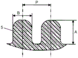
Fig. 9A is a plan view of the back surface of the conventional toilet seat described in patent document 1, and fig. 9B is a cross-sectional view of a projection provided in the conventional toilet seat described in patent document 1. As shown in fig. 9A, the rear surface 2 of the toilet seat 1 is integrally formed with a front flat surface portion 3 of the toilet seat 1 and a rear inclined portion 4 of the toilet seat 1, and a protrusion 5 as shown in fig. 9B is formed over substantially the entire surfaces of the flat surface portion 3 and the inclined portion 4.
As shown in fig. 9B, the protrusion 5 has a substantially cylindrical shape, and a tip end portion is formed in a substantially hemispherical shape. The protrusion 5 has a shape with a height a of about 5 μm and a width direction length B of about 5 μm. The distance P between the central axes of the projections 5 is set to about 10 μm.
However, in the above-described conventional structure, when the flat surface portion 3 and the inclined portion 4 are integrally molded, for example, as shown in fig. 9B, when the tip portions of the protrusions 5 of the flat surface portion 3 are arranged at the same height, the tip portions of the protrusions 5 of the inclined portion 4 are arranged with steps instead of being arranged at the same height in consideration of the mold releasing direction at the time of molding. In such a case, the contact angle between the tip of the protrusion 5 and water cannot be maintained at an appropriate angle, and there is a problem in that the water repellent function is lowered.
Prior art literature
Patent literature
Patent document 1: japanese patent laid-open No. 2017-12351
Disclosure of Invention
The present disclosure has been made in view of the above-described conventional problems, and provides a high-performance toilet seat having the same water-repellent performance on the entire back surface of the toilet seat.
Specifically, the toilet seat of the present disclosure includes a substantially horizontal main body portion and a support portion inclined obliquely upward from a rear portion of the main body portion in a horizontally disposed state. A substantially flat horizontal surface of the lower surface of the main body and an inclined surface of the lower surface of the support part are continuously formed on the lower surface of the toilet seat. Further, the toilet seat of the present disclosure includes a water-repellent treatment portion in which a convex portion and a concave portion are continuously formed in a ridge shape from a substantially front end of a horizontal plane of a lower surface of the main body portion to a substantially rear end of an inclined plane of a lower surface of the supporting portion. According to an example of the present disclosure, the protruding portions are arranged such that the interval between adjacent protruding portions is 2 μm or more and 40 μm or less. The depth of the recess is 10 μm or more.
With this structure, the contamination of the lower surface of the toilet seat can be suppressed, and the cleaning performance of the toilet seat can be improved. In addition, since the mold release direction can be uniform at the time of molding, the manufacturing of the mold and the molding operation can be simplified, and the toilet seat can be provided at low cost. Further, since the water-repellent treatment portion has a continuous ridge shape, when the water-repellent treatment portion is attached with an attached matter or dirt, the water-repellent treatment portion is easily cleaned by wiping. Further, the effect of suppressing the abrasion and deformation of the protruding portion can be obtained, and a toilet seat which is sanitary and has high durability can be provided at low cost. Further, a toilet seat device according to an aspect of the present disclosure includes a main body that can be provided in a toilet and the toilet seat of the present disclosure rotatably pivotally supported by the main body.
Thus, according to the present disclosure, contamination of the lower surface of the toilet seat can be suppressed, and a toilet seat having high durability and hygiene and a toilet seat device including the same can be provided at low cost.
Drawings
Fig. 1 is a perspective view showing an external appearance of a toilet seat device according to an embodiment of the present disclosure.
Fig. 2 is a perspective view showing an appearance of a finished state of the toilet seat according to the embodiment of the present disclosure.
Fig. 3 is a view of the completed state of the toilet seat according to the embodiment of the present disclosure, viewed from the side.
Fig. 4 is a perspective view for explaining the structure of components of the toilet seat according to the embodiment of the present disclosure.
Fig. 5 is a schematic view showing a lower surface of a toilet seat according to an embodiment of the present disclosure.
Fig. 6 is a schematic view showing a section 6-6 of fig. 5.
Fig. 7 is a schematic diagram showing details of the portion D shown in fig. 6.
Fig. 8A is a schematic diagram illustrating the contact angle of the surface of the substrate with the outer surface of the water droplet.
Fig. 8B is a schematic diagram illustrating the roll-off angle of water droplets on a substrate.
Fig. 9A is a plan view showing the lower surface of a conventional toilet seat.
Fig. 9B is a cross-sectional view of a protrusion of a conventional toilet seat.
Detailed Description
The toilet seat according to one embodiment of the present disclosure includes a substantially horizontal main body portion and a support portion inclined obliquely upward from a rear portion of the main body portion in a horizontally disposed state. The substantially flat horizontal surface of the lower surface of the main body portion is formed continuously with the inclined surface of the lower surface of the support portion. The toilet seat according to one embodiment of the present disclosure includes a water-repellent treatment portion in which a convex portion and a concave portion are continuously formed so as to form a ridge shape from a substantially front end of the horizontal surface to a substantially rear end of the inclined surface. The convex portions of the toilet seat according to one embodiment of the present disclosure are arranged at intervals of 2 μm or more and 50 μm or less. In addition, the depth of the concave portion of the toilet seat according to one embodiment of the present disclosure is 10 μm or more.
With this structure, the contamination of the lower surface of the toilet seat can be suppressed, and the cleaning performance of the toilet seat can be improved. In addition, since the demolding direction can be uniform at the time of molding, the manufacturing of the mold and the molding operation can be simplified, and the toilet seat can be provided at low cost. Further, since the lower surface of the toilet seat has a continuous ridge shape, when the water repellent treatment is attached with the attached matter or dirt, the cleaning by wiping is easy. Further, with such a structure, the effect of suppressing the abrasion and deformation of the convex portion can be obtained. With this structure, a toilet seat with high durability and hygiene can be provided at low cost.
The toilet seat according to one embodiment of the present disclosure is preferably configured such that the cross-sectional shape of the protruding portion is substantially triangular.
With such a structure, the water repellency can be further improved. In addition, the manufacturing cost of the mold can be further reduced, and the operation of taking out the molded product during molding can be facilitated, so that the deformation of the molded product can be suppressed.
The toilet seat according to an example of the embodiment of the present disclosure may have a flat outer peripheral edge on the outer periphery of the water-repellent treatment portion, and a flat inner peripheral edge on the inner periphery of the water-repellent treatment portion. In this case, the convex portion is preferably configured not to protrude with respect to the surfaces of the outer peripheral edge and the inner peripheral edge.
With such a structure, the effect of suppressing deformation or breakage of the convex portion of the water-repellent treatment portion during use of the toilet seat can be obtained.
A toilet seat according to an example of the embodiment of the present disclosure may be provided with a toilet seat heater for heating the main body.
With such a structure, the comfort of the toilet seat can be improved.
The toilet seat device according to one embodiment of the present disclosure includes: a main body which can be provided on a toilet; and a toilet seat pivotally supported by the main body so as to be rotatable.
With such a configuration, contamination of the toilet seat can be suppressed, and a sanitary toilet seat device can be provided at low cost.
Hereinafter, embodiments of the present disclosure will be described with reference to the drawings. The present disclosure is not limited to the following embodiments.
(embodiment)
Fig. 1 is a perspective view showing an external appearance of a toilet seat device 100 according to an embodiment of the present disclosure.
Structure of toilet seat device with less than 1
As shown in fig. 1, the toilet seat device 100 includes a main body 200 and a toilet seat 300. The toilet seat apparatus 100 may also include a toilet cover 400. The toilet seat device 100 is configured to be provided on the upper surface of the toilet 110.
In the present embodiment, the arrangement of the components will be described by setting the installation side of the main body 200 of the toilet seat device 100 to the rear, setting the installation side of the toilet seat 300 to the front, setting the right side when viewed from the front to the right, and setting the left side when viewed from the front to the left.
In the present embodiment, the toilet seat 300 and the toilet cover 400 are openably and closably attached to the main body 200 by a rotation mechanism. As shown in fig. 1, the toilet cover 400 is configured such that the toilet cover 400 stands up so as to be positioned at the rearmost part of the toilet seat device 100 in a state where the toilet cover 400 is opened, and such that the toilet cover 400 covers the upper surface of the toilet seat 300 and a part of the main body 200 in a state where the toilet cover 400 is closed. As shown in fig. 1, the toilet seat 300 is configured to stand on the front surface of the main body 200 in the same manner as the toilet cover 400 from the state of being placed on the upper surface of the toilet 110.
In the present embodiment, a cleaning mechanism including a cleaning water supply mechanism (not shown), a heat exchanger (not shown), a cleaning nozzle 201, and the like, a drying unit (not shown), a control unit (not shown), and the like are incorporated in the main body 200.
Further, a seating sensor (not shown) for detecting a human body seated on the toilet seat 300 is provided at a bearing portion in the main body 200 supporting the rotation shaft of the toilet seat 300. For example, a weight type seating sensor is used as the seating sensor. The weight type seating sensor is configured to detect a state in which a user is seated on the toilet seat 300 by opening and closing a switch according to a weight change caused by the user being seated on the toilet seat 300.
Further, a cleaning water supply mechanism and a heat exchanger are connected to the cleaning nozzle 201. The cleaning water supplied from the water channel pipe is heated by the heat exchanger, and the heated warm cleaning water is supplied to the cleaning nozzle 201. Then, the washing water is sprayed from the washing nozzle 201 toward the user's private parts, and the private parts of the user are washed by the sprayed washing water. The cleaning nozzle 201 may also include at least any one of a buttock cleaning nozzle section for cleaning buttocks and a female nozzle section for cleaning private parts of a female.
The drying unit is configured to spray warm air toward the private parts wetted with the washing water and dry the private parts.
The cleaning mechanism and the drying unit are not essential components of the toilet seat device 100, and the toilet seat device 100 may be provided without these components.
Further, a sleeve portion 210 is provided on the right side of the main body 200 so as to protrude forward. An operation portion 211 is provided on the upper surface of the sleeve portion 210. In the present embodiment, the operation unit 211 is provided with a plurality of operation switches 212 and display lamps 213 for operating the respective functions of the toilet seat device 100.
Structure of toilet seat with less than 2
Fig. 2 is a perspective view showing an appearance of a finished state of the toilet 300 according to the embodiment of the present disclosure. Fig. 3 is a view of the completed state of the toilet seat 300 according to the embodiment of the present disclosure, viewed from the side. Fig. 4 is a perspective view for explaining the structure of components of the toilet seat 300 according to the embodiment of the present disclosure. Fig. 5 is a schematic view showing a lower surface of a toilet seat according to an embodiment of the present disclosure. Fig. 6 is a schematic view showing a section 6-6 of fig. 5.
As shown in fig. 2 and 3, the toilet seat 300 is formed in a substantially elliptical ring shape. The toilet 300 mainly includes a main body 301 on which a user sits and a support 302 inclined obliquely upward from the rear of the main body 301. The toilet seat 300 is pivotally supported by the main body 200 by a pivot shaft 303 formed at the rear end of the support portion 302.
As shown in fig. 1, in a state in which the toilet seat 300 is placed upside down on the upper surface of the toilet 110, the lower surface of the main body 301 of the toilet seat 300 is substantially horizontal, and the lower surface of the support 302 is inclined obliquely upward.
As shown in fig. 4 and 6, the toilet 300 is configured by using, as main structural members, an upper toilet case 310 integrally molded from a resin material mainly composed of polypropylene, a toilet heater 330 provided with heating wires (not shown) in a soaking plate made of aluminum foil, and a lower toilet case 320 integrally molded from a resin material mainly composed of polypropylene, from the upper surface side. In its completed state, the upper toilet seat case 310 and the lower toilet seat case 320 are engaged with each other at their inner and outer peripheral edges to form an annular shape with a hollow interior.
As shown in fig. 4, the upper toilet seat case 310 is integrally molded by injection molding using a resin material mainly made of polypropylene. The upper toilet seat case 310 includes a seating portion 311 formed in a substantially elliptical ring-like shape constituting the main body 301, and an upper support portion 312 protruding obliquely upward from a rear end portion of the seating portion 311 constituting the support portion 302.
As shown in fig. 6, the upper toilet seat case 310 is formed such that the cross section of the seating portion 311 has a substantially mountain shape. The upper surface of the seating portion 311 is formed into a gently curved surface suitable for seating. The inner and outer circumferences of the seating portion 311 are curved downward, and the tip end portion thereof is formed with substantially perpendicular inner and outer circumferences.
As shown in fig. 4, the lower toilet seat case 320 is integrally molded by injection molding using a resin material mainly made of polypropylene. The lower toilet seat case 320 is formed in a substantially elliptical ring shape having substantially the same shape as the seating portion 311 of the upper toilet seat case 310. The lower toilet seat case 320 includes a lower body portion 321 and a lower support portion 322. The lower support portion 322 has substantially the same shape as the upper support portion 312 of the upper toilet seat case 310, and is formed to protrude obliquely upward from the rear end portion of the lower body portion 321.
The lower toilet seat case 320 has an inner periphery and an outer periphery bent upward, and an inner periphery and a lower outer periphery formed at a distal end portion thereof.
The inner and outer circumferences of the upper and lower toilet housings 310 and 320 have substantially the same shape, respectively. The toilet seat 300 is formed in a continuous external shape by the abutment and coupling of the upper toilet seat case 310 and the lower toilet seat case 320, and is configured such that a hollow portion 304 is formed inside the toilet seat 300 as shown in fig. 6.
The lower body 321 of the toilet 300 and the lower surface of the lower support 322 are formed in a continuous planar shape. A water-repellent treatment 340 having a substantially linear concave-convex shape and exhibiting water-repellent performance is formed on the planar lower surface of the toilet seat 300. Details of the water repellent treatment 340 will be described later.
The toilet heater 330 has the following configuration: the heating wire covered with the soft insulating cover made of polyvinyl chloride is arranged in a zigzag manner at intervals on the surface of the vapor chamber formed by the aluminum foil with a substantially horseshoe shape, the front part of which is partially cut off. The toilet heater 330 is configured such that heat generated by the heating wire is transferred to the soaking plate and spread over the entire surface of the soaking plate. The toilet heater 330 is adhesively secured to the inner surface of the upper toilet housing 310.
A thermistor as a temperature detecting means and a thermostat as an overheat preventing means, not shown, are provided on the surface of the soaking plate. The heating wire, the thermistor and the thermostat are connected by leads.
Structure of & lt 3 & gtwater repellent treatment part
As shown in fig. 5, the lower surface of the lower toilet seat case 320 is continuously and integrally formed with a horizontal portion 323 corresponding to the lower body portion 321 and an inclined portion 324 corresponding to the lower support portion 322. The switching portion 325 of the horizontal portion 323 and the inclined portion 324 is connected by a curved surface disposed substantially linearly behind the lower toilet seat case 320.
The water repellent treatment 340 is formed on substantially the entire surfaces of the horizontal portion 323 and the inclined portion 324. Further, a flat outer peripheral edge 351 and an inner peripheral edge 352 (see fig. 5) formed in a band shape along the outer periphery and the inner periphery are formed on the outer periphery and the inner periphery of the water-repellent treatment portion 340, respectively.
In the water repellent treatment 340, fine irregularities of micrometer scale are formed continuously in a substantially straight line so as to form a ridge line from substantially the front end of the horizontal portion 323 to substantially the rear end of the inclined portion 324. More specifically, in the water-repellent treatment portion 340, a convex shape and a groove shape are formed so that ridge lines are formed in a direction orthogonal to the switching portion 325.
With such a configuration, when the same concave-convex shape is formed in the horizontal portion 323 and the inclined portion 324 having different angles by injection molding, the mold release direction at the time of molding can be uniformed, and therefore, the manufacturing of the mold and the molding operation can be simplified.
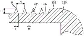
Fig. 7 is a schematic diagram showing details of the portion D shown in fig. 6.
As shown in fig. 7, the cross-sectional shape of the convex portion 341 of the water-repellent treatment portion 340 is substantially triangular, and the bottom of the concave portion 342 of the water-repellent treatment portion 340 is formed to be substantially planar. The convex portions 341 and the concave portions 342 are alternately formed at equal intervals.
In the present embodiment, the convex portion 341 is formed in a triangular shape having a height H of approximately 23 μm and a length L of the base of approximately 18 μm. The tip of the convex portion 341 is formed to have a radius R of 1 μm or less. In the case of the triangular shape of the above-described size, the tip end portion of the convex portion 341 is formed at approximately 45 degrees. The angle of the distal end portion of the convex portion 341 is preferably from about 45 degrees to about 70 degrees. In addition, the height H of the convex portion 341 is preferably 10 μm or more in terms of water repellency, and the height H of the convex portion 341 is preferably 50 μm or less in terms of strength or the like.
The width M of the bottom edge of the recess 342 of the water-repellent treatment 340 is formed to be approximately 15 μm. The uneven shapes of the water repellent treatment 340 are set such that the pitch N between the tip portions of the adjacent convex portions 341 is approximately 33 μm. The uneven shape is formed over the entire surface of the water-repellent treatment 340. The pitch N of the concave-convex shape is preferably 2 μm or more and 50 μm or less.
As shown in fig. 6, the tip end of the convex portion 341 is disposed at a position not protruding from the surfaces of the outer peripheral edge 351 and the inner peripheral edge 352 adjacent to the water-repellent treatment portion 340. With such a structure, the effect of suppressing deformation or breakage of the convex portion 341 in use of the toilet seat 300 can be obtained.
Effect of water repellent treatment part of < 4 ]
Fig. 8A is a schematic diagram illustrating the contact angle of the surface of the substrate with the outer surface of the water droplet. Fig. 8B is a schematic diagram illustrating the roll-off angle of water droplets on a substrate.
When water is applied to the water-repellent treatment portion 340 having the above-described structure by scattering of urine, cleaning water, or the like, the water becomes water droplets on the surface of the water-repellent treatment portion 340 and adheres thereto. By tilting the toilet seat 300 provided with the water-repellent treatment portion 340, the attached water drops fall from the surface of the water-repellent treatment portion 340 according to the tilt angle.
For example, when urine or cleaning water is applied to the water-repellent treatment unit 340 in a state where the toilet seat 300 is raised, the urine or cleaning water is formed into small water droplets and slides down along the irregularities of the water-repellent treatment unit 340 to fall into the toilet bowl 110.
In general, as an index for evaluating the water repellency, evaluation was made based on a contact angle E as shown in fig. 8A and a roll-off angle F as shown in fig. 8B. That is, it is evaluated that the larger the contact angle E, the smaller the roll-off angle F, and the higher the water repellency.
As shown in fig. 8A, the contact angle E is an angle formed by the contact surface of the substrate 360 and the outer surface of the water droplet in a state where the water droplet is attached to the surface of the substrate 360. The closer the contact angle is to 0 degrees, the easier it is for the substrate 360 and the water droplet to adhere, and the closer the contact angle is to 180 degrees, the more difficult it is for the water droplet to adhere to the substrate 360.
As shown in fig. 8B, the roll-off angle F is an angle at which the substrate 360 to which the water droplets adhere gradually tilts from a horizontal position and the droplets start to slip. The closer the roll-off angle F is to 0 degrees, the easier it is for the water droplets to be removed from the substrate 360, and the closer the roll-off angle F is to 90 degrees, the more difficult it is for the water droplets to separate from the substrate 360.
In the case of a normally molded polypropylene material which has not been subjected to water repellency treatment, the contact angle E is about 90 degrees, and the roll angle F is 90 degrees or more.
In contrast, the water-repellent treatment unit 340 of the present embodiment can exhibit water-repellent performance in which the contact angle E is 150 degrees or more and the roll angle F is 30 degrees or less.
Further, the water repellent treatment 340 of the present embodiment is formed with fine ridge-like concave-convex shapes continuously in a substantially straight line from the substantially front end of the horizontal portion 323 to the substantially rear end of the inclined portion 324. With such a configuration, the demolding direction of the mold at the time of molding can be unified. Thus, the manufacturing and molding operations of the mold can be simplified, and the toilet seat 300 having excellent water repellency can be provided at low cost.
In particular, by forming the convex portion 341 so that the cross-sectional shape of the convex portion becomes substantially triangular, the water repellency can be further improved. In addition, with such a structure, the manufacturing cost of the mold can be reduced. Further, with such a configuration, the operation of taking out the molded article at the time of molding is facilitated, and deformation of the molded article can be suppressed.
The water repellent treatment 340 of the present embodiment is configured to have a continuous ridge shape. With such a configuration, when the water repellent treatment portion 340 is attached with the attached matter or dirt, cleaning by wiping is easy. Further, with such a structure, the effect of suppressing the wear and deformation of the convex portion 341 can be obtained, and durability can be improved.
In the present embodiment, the tip end portions of the convex portions 341 of the water-repellent treatment portion 340 are configured not to protrude from the surfaces of the outer peripheral edge 351 and the inner peripheral edge 352 adjacent to the water-repellent treatment portion 340. With such a structure, the effect of suppressing deformation or breakage of the convex portion 341 of the water-repellent treatment portion 340 during use of the toilet seat 300 can be obtained.
In the present embodiment, the cross-sectional shape of the protruding portion 341 is a simple triangle, but the present invention is not limited to this, and for example, the portion of the tip end portion on the opposite side to the tip end portion may be formed in two stages, that is, a portion having an acute angle and an obtuse angle. By adopting such a shape for the convex portion 341, the strength of the convex portion 341 can be increased.
In the present embodiment, the cross-sectional shape of the protruding portion 341 is a substantially triangular shape, but the present invention is not limited to this, and may be a substantially circular arc shape, a substantially trapezoidal shape, or a combination of these shapes.
In the present embodiment, polypropylene as a material used for the toilet seat 300 is used as a main material, but the present invention is not limited thereto, and other resin materials such as ABS resin used for a general molded article may be used.
Industrial applicability
As described above, the present disclosure can be used for a toilet seat and a toilet seat device which have high durability and can perform water repellency treatment at low cost, and can also be used for other applications such as water use equipment using molded articles of resin materials.
Description of the reference numerals
100. A toilet seat device; 110. a toilet bowl; 200. a main body; 201. cleaning the nozzle; 210. a sleeve part; 211. an operation unit; 212. an operation switch; 213. a display lamp; 300. a toilet seat; 301. a main body portion; 302. a support section; 303. a pivot support shaft; 304. a hollow portion; 310. an upper toilet seat case; 311. a seating portion; 312. an upper support portion; 320. a lower toilet seat shell; 321. a lower body portion; 322. a lower support portion; 323. a horizontal portion (horizontal plane); 324. an inclined portion (inclined surface); 325. a switching section; 330. a toilet seat heater; 340. a water-repellent treatment section; 341. a convex portion; 342. a concave portion; 351. an outer peripheral edge; 352. an inner periphery; 360. a substrate.
Claims (5)
1. A toilet seat comprising a substantially horizontal main body part and a support part having a shape inclined obliquely upward from the rear part of the main body part in a horizontally arranged state,
a substantially flat horizontal surface of the lower surface of the main body portion is formed continuously with the inclined surface of the lower surface of the supporting portion,
the toilet seat further includes a water-repellent treatment portion in which a convex portion and a concave portion are continuously formed in a ridge shape from a substantially front end of the horizontal surface to a substantially rear end of the inclined surface,
the convex portions are arranged at intervals of 2 μm or more and 50 μm or less, the depth of the concave portions is 10 μm or more,
the water-repellent treatment portion has a flat outer periphery at an outer periphery of the water-repellent treatment portion, and has a flat inner periphery at an inner periphery of the water-repellent treatment portion,
the convex portion is formed so as not to protrude with respect to the surfaces of the outer peripheral edge and the inner peripheral edge.
2. The toilet according to claim 1, wherein,
the convex portion is formed to have a substantially triangular cross-sectional shape.
3. The toilet according to claim 1, wherein,
the convex portion (341) has a triangular cross-sectional shape,
sandwiching the concave portion (342) between two of the convex portions (341), and,
the recess (342) has a bottom formed to be planar.
4. The toilet according to any one of claim 1 to 3, wherein,
the toilet also includes a toilet heater for heating the main body.
5. A toilet seat device, wherein,
the toilet seat device comprises:
a main body which can be provided on a toilet; and
the toilet seat according to any one of claims 1 to 4, pivotally supported by the main body so as to be rotatable.
Applications Claiming Priority (3)
| Application Number | Priority Date | Filing Date | Title |
|---|---|---|---|
| JP2020191372 | 2020-11-18 | ||
| JP2020-191372 | 2020-11-18 | ||
| PCT/JP2021/020995 WO2022107363A1 (en) | 2020-11-18 | 2021-06-02 | Toilet seat, and toilet seat device provided with same |
Publications (2)
| Publication Number | Publication Date |
|---|---|
| CN114828719A CN114828719A (en) | 2022-07-29 |
| CN114828719B true CN114828719B (en) | 2023-07-07 |
Family
ID=81708692
Family Applications (1)
| Application Number | Title | Priority Date | Filing Date |
|---|---|---|---|
| CN202180004938.9A Active CN114828719B (en) | 2020-11-18 | 2021-06-02 | Toilet seat and toilet seat device with same |
Country Status (4)
| Country | Link |
|---|---|
| JP (1) | JPWO2022107363A1 (en) |
| CN (1) | CN114828719B (en) |
| TW (1) | TW202220604A (en) |
| WO (1) | WO2022107363A1 (en) |
Family Cites Families (6)
| Publication number | Priority date | Publication date | Assignee | Title |
|---|---|---|---|---|
| JP2017012351A (en) * | 2015-06-30 | 2017-01-19 | アイシン精機株式会社 | Warm water washing toilet seat device |
| CN205348331U (en) * | 2015-10-28 | 2016-06-29 | 北京美晟博恩科技有限公司 | Waterproof function toilet bowl |
| WO2018128092A1 (en) * | 2017-01-05 | 2018-07-12 | パナソニックIpマネジメント株式会社 | Molded body |
| WO2018198667A1 (en) * | 2017-04-28 | 2018-11-01 | Toto株式会社 | Toilet seat |
| JP6688488B2 (en) * | 2017-04-28 | 2020-04-28 | Toto株式会社 | toilet seat |
| JP6967699B2 (en) * | 2017-11-10 | 2021-11-17 | パナソニックIpマネジメント株式会社 | toilet seat |
-
2021
- 2021-06-02 CN CN202180004938.9A patent/CN114828719B/en active Active
- 2021-06-02 JP JP2022511239A patent/JPWO2022107363A1/ja active Pending
- 2021-06-02 WO PCT/JP2021/020995 patent/WO2022107363A1/en active Application Filing
- 2021-06-03 TW TW110120266A patent/TW202220604A/en unknown
Also Published As
| Publication number | Publication date |
|---|---|
| CN114828719A (en) | 2022-07-29 |
| TW202220604A (en) | 2022-06-01 |
| WO2022107363A1 (en) | 2022-05-27 |
| JPWO2022107363A1 (en) | 2022-05-27 |
Similar Documents
| Publication | Publication Date | Title |
|---|---|---|
| US7565715B2 (en) | Cleaning implement | |
| CN114828719B (en) | Toilet seat and toilet seat device with same | |
| AU2013364407B2 (en) | Oral care implement comprising mirror and light distributive element, and method of forming the same | |
| CN101548860A (en) | Sanitary washing device | |
| JP2010051781A (en) | Sanitary washing device | |
| JP2013000443A (en) | Toilet seat heater | |
| CN100521426C (en) | Housing pertaining to a household appliance for culinary purposes | |
| CN110710917B (en) | Toilet seat device | |
| JP5604908B2 (en) | Interchangeable toilet seat | |
| JP3177132U (en) | Mall for preventing urination scattering | |
| KR20090105853A (en) | Sanitary washing apparatus | |
| US1237673A (en) | Bed-pan. | |
| KR200441492Y1 (en) | Control apparatus of bidet | |
| JP3224915U (en) | Urine leak prevention equipment | |
| CN217827749U (en) | Anti-overturning flat mop | |
| US970779A (en) | Shaving-cup. | |
| USD483691S1 (en) | Belt adjuster | |
| KR200386418Y1 (en) | Cover for seat on closestool | |
| USD437143S1 (en) | Sleep surface | |
| JP2003135363A (en) | Dish dryer | |
| JP2022062459A (en) | Toilet seat cover | |
| JPS6219745Y2 (en) | ||
| JPH03266975A (en) | Petri dish | |
| JP2022067918A (en) | Toilet seat unit, toilet, and simple toilet | |
| KR20070042593A (en) | Pizza delivery apparatus and pizza box |
Legal Events
| Date | Code | Title | Description |
|---|---|---|---|
| PB01 | Publication | ||
| PB01 | Publication | ||
| SE01 | Entry into force of request for substantive examination | ||
| SE01 | Entry into force of request for substantive examination | ||
| GR01 | Patent grant | ||
| GR01 | Patent grant |