CN114803354B - Transfer robot based on AGV - Google Patents
Transfer robot based on AGV Download PDFInfo
- Publication number
- CN114803354B CN114803354B CN202210537988.XA CN202210537988A CN114803354B CN 114803354 B CN114803354 B CN 114803354B CN 202210537988 A CN202210537988 A CN 202210537988A CN 114803354 B CN114803354 B CN 114803354B
- Authority
- CN
- China
- Prior art keywords
- plate
- sliding
- connecting rod
- block
- rod
- Prior art date
- Legal status (The legal status is an assumption and is not a legal conclusion. Google has not performed a legal analysis and makes no representation as to the accuracy of the status listed.)
- Active
Links
Images


Classifications
-
- B—PERFORMING OPERATIONS; TRANSPORTING
- B65—CONVEYING; PACKING; STORING; HANDLING THIN OR FILAMENTARY MATERIAL
- B65G—TRANSPORT OR STORAGE DEVICES, e.g. CONVEYORS FOR LOADING OR TIPPING, SHOP CONVEYOR SYSTEMS OR PNEUMATIC TUBE CONVEYORS
- B65G35/00—Mechanical conveyors not otherwise provided for
-
- B—PERFORMING OPERATIONS; TRANSPORTING
- B65—CONVEYING; PACKING; STORING; HANDLING THIN OR FILAMENTARY MATERIAL
- B65G—TRANSPORT OR STORAGE DEVICES, e.g. CONVEYORS FOR LOADING OR TIPPING, SHOP CONVEYOR SYSTEMS OR PNEUMATIC TUBE CONVEYORS
- B65G47/00—Article or material-handling devices associated with conveyors; Methods employing such devices
- B65G47/74—Feeding, transfer, or discharging devices of particular kinds or types
- B65G47/90—Devices for picking-up and depositing articles or materials
Landscapes
- Engineering & Computer Science (AREA)
- Mechanical Engineering (AREA)
- Manipulator (AREA)
Abstract
The invention discloses a transfer robot based on an AGV, and relates to the technical field of AGV transfer. According to the cable roller clamping device, the cable roller can be clamped through the grabbing assembly, the upper supporting block and the lower supporting block are respectively supported on the inner side wall of the cable roller, and the first side plate and the second side plate are fixed on the outer side wall of the cable roller and are used for preventing the cable roller from rolling in the cable roller carrying process. In the transfer robot transportation based on AGV, press from both sides tight transfer pole between two dogs, prevent that the production from rocking in the transfer pole transportation, after transporting to the destination, two dogs loosen with the transfer pole, place the cable winding up roller at the transportation destination.
Description
Technical Field
The invention belongs to the technical field of AGV transportation, and particularly relates to a transport robot based on an AGV.
Background
An AGV is an "automatic guided vehicle" equipped with an electromagnetic or optical automatic guide device, capable of traveling along a predetermined guide path, and having safety protection and various transfer functions. Generally, the traveling route and behavior can be controlled by a computer, or the traveling route can be set up by an electromagnetic track, which is adhered to the floor, and the unmanned vehicle can move and operate according to the information from the electromagnetic track.
In the prior art, a chinese utility model with application number CN201922262500.3 discloses an intelligent AGV transport trolley and a trolley transport travelling mechanism thereof, after an operator starts the intelligent AGV transport trolley, a PLC controller sends commands such as forward, backward or lateral movement, and the commands are transmitted to a communication line through a communication port, and then are transmitted to communication ports of a front steering wheel controller and a rear steering wheel controller through the communication line; after the front and rear steering wheel controllers obtain the commands, the front and rear magnetic navigation sensors can automatically acquire position offset information transmitted to the front and rear steering wheel controllers through the communication lines, then calculate the offset of the vehicle, and then send the adjusted offset information to the communication port of the steering wheel controllers; the front and rear steering wheels corresponding to the front and rear steering wheel traveling mechanisms are adjusted at any time according to requirements, so that the intelligent AGV carrying trolley is fast and accurate in response adjustment, and is not suitable for carrying cable rollers.
Disclosure of Invention
The invention aims to overcome the defects of the prior art and provide the AGV-based transfer robot which is stable in transfer, high in transfer efficiency and suitable for transferring the cable roller.
The technical scheme for solving the technical problems is as follows: the bottom of four corners of a chassis of the AGV is respectively provided with a first motor, an output shaft of the first motor is fixedly connected with a first connecting shaft, the outer circumference of the first connecting shaft is provided with a roller, the chassis is provided with a balancing weight, the balancing weight is provided with a supporting seat, two sides of the chassis are provided with two height adjusting components for adjusting the height of the supporting seat, two sides of the supporting seat are respectively provided with a carrying rod through two horizontal adjusting components, the horizontal adjusting components are provided with angle adjusting components for adjusting the carrying rods, and the two carrying rods are provided with grabbing components for clamping cable winding rollers; the grabbing component is as follows: a first fixing plate is fixedly installed between the two carrying rods, a third connecting plate and a fourth connecting plate are connected to the first fixing plate in a sliding mode through a driving unit, the moving direction of the third connecting plate is opposite to the moving direction of the fourth connecting plate, and fastening units used for fixing the cable winding roller are arranged on the third connecting plate and the fourth connecting plate respectively.
Further, the driving unit is: the third connecting plate is provided with a first rack, the fourth connecting plate is provided with a second rack, the first fixing plate is provided with a second motor for driving the gear to rotate, the gear is respectively in meshing transmission with the first rack and the second rack, and the moving direction of the first rack is opposite to that of the second rack.
Further, the fastening unit is: a third connecting plate is provided with a push plate, the push plate is provided with an upper supporting block which is contacted with the upper side wall of the inner circumference of the cable winding roller, the upper supporting block is connected with a lower supporting block in a sliding way through a fourth connecting shaft, the lower supporting block is contacted with the lower side wall of the inner circumference of the cable winding roller, and a third spring is arranged on the fourth connecting shaft; the second connecting plate is connected with a second sliding plate in a sliding mode, one end of the second sliding plate is connected with the third connecting plate through a second spring, the other end of the second sliding plate is in contact with the outer side wall of the cable winding roll, the second sliding plate is fixedly connected with one end of a fifth connecting plate, the other end of the fifth connecting plate is provided with a push block, the inclined surface of the push block is in contact with the inclined surface of the lower supporting block, the fifth connecting plate is rotatably connected with one end of a first connecting rod and one end of a second connecting rod through a third connecting shaft, two first sliding holes are formed in two sides of the push plate respectively, a first sliding block and a second sliding block are slidably connected in the two first sliding holes respectively, the first sliding blocks and the second sliding blocks on two sides are connected through second connecting shafts respectively, the other end of the first connecting rod is rotatably connected with the second connecting shaft on one side of the push plate, the other end of the second connecting rod is rotatably connected with the second connecting shaft on the other side of the push plate, first sliding block and the second sliding block on one side of the other side of the push plate are fixedly connected with one end of the cable winding roll, and the first side plate and the second side plate are in contact with the outer side wall of the cable winding roll respectively.
Further, the vehicle chassis on be provided with brake assembly, brake assembly is: a first supporting plate is arranged on a chassis and is provided with a third motor for driving a rotary disc to rotate, the rotary disc is rotatably connected with two eccentric rods, two third sliding holes in the first supporting plate are respectively and slidably connected with a fourth sliding block, the two eccentric rods are respectively and rotatably connected with the two fourth sliding blocks, the fourth sliding block is hinged with one end of a fourth connecting rod, two ends of the first supporting plate are respectively provided with a second fixing plate, a second sliding hole in the second fixing plate is slidably connected with a third sliding block, one side of the third sliding block is rotatably connected with one end of the third connecting rod through a fifth connecting shaft, the other end of the third connecting rod is rotatably connected with a fixing component, the other side of the third sliding block is rotatably connected with a sixth connecting shaft, and the sixth connecting shaft is fixedly connected with the other end of the fourth connecting rod; the third slider is rotatably connected with a fifth connecting rod and a sixth connecting rod through a seventh connecting shaft, the fifth connecting rod is rotatably connected with one end of an eighth connecting rod, the other end of the eighth connecting rod is provided with a second brake plate clamped with the outer circumferential surface of the roller, the sixth connecting rod is rotatably connected with one end of the seventh connecting rod, and the other end of the seventh connecting rod is provided with a first brake plate clamped with the outer circumferential surface of the roller.
Further, the fixing component is: sliding connection has two first slides in the spout of supporting seat, and the horizontal plate of two first slides passes through second connecting plate fixed connection, and sliding connection has first connecting plate on the vertical plate of first slide, through first spring coupling between the horizontal plate of first connecting plate and the horizontal plate of first slide, evenly is provided with the dog on the vertical plate of first connecting plate, is used for the fixed transport pole between two adjacent dogs.
Further, the height adjusting assembly is: a fourth motor for driving the first screw rod to rotate is arranged on a second supporting plate on the chassis, a sixth sliding block is connected onto the first screw rod in a sliding mode, the sixth sliding block is connected with a ninth connecting rod and a tenth connecting rod which are connected in a crossed mode in a rotating mode through an eighth connecting shaft, lower sliding groove plates are fixedly arranged on the two sides of the chassis respectively, seventh sliding blocks are connected with fourth sliding holes of the two lower sliding groove plates in a sliding mode respectively, upper sliding groove plates which are symmetrical to the lower sliding groove plates are fixedly arranged on the two sides of the lower side face of the supporting seat respectively, fifth sliding holes of the two upper sliding groove plates are connected with fifth sliding blocks in a sliding mode respectively, one end of the ninth connecting rod is hinged to one of the fifth sliding blocks, the other end of the ninth connecting rod is hinged to one of the seventh sliding blocks, one end of the tenth connecting rod is hinged to the other fifth sliding block, and the other end of the tenth connecting rod is hinged to the other seventh sliding block.
Further, the horizontal adjusting component is: a third supporting plate on the supporting seat is provided with a fifth motor for driving a second screw rod to rotate, a third sliding plate is connected to the second screw rod in a sliding mode, and a carrying rod is arranged on the third sliding plate through an angle adjusting assembly.
Further, the angle adjusting assembly is as follows: the fourth supporting plate is provided with a sixth motor for driving the third screw rod to rotate, the third screw rod is connected with an eighth sliding block in a sliding mode, the eighth sliding block is connected with one end of an eleventh connecting rod in a rotating mode, and the other end of the eleventh connecting rod is connected with a carrying rod in a rotating mode through the eleventh connecting rod.
The invention has the following beneficial effects: (1) The height adjusting assembly is adopted to adjust the height of the supporting seat, the horizontal adjusting assembly is used to adjust the horizontal position of the carrying rod, the angle adjusting assembly is used to adjust the angle of the carrying rod, the grabbing position of the carrying rod can be adjusted, and the cable roll grabbing device has the advantage of accurately grabbing a cable roll.
(2) The cable winding roller clamping device adopts the grabbing component to clamp the cable winding roller, the upper supporting block and the lower supporting block are respectively supported on the inner side wall of the cable winding roller, and the first side plate and the second side plate are fixed on the outer side wall of the cable winding roller and are used for preventing the cable winding roller from rolling in the cable winding roller carrying process.
(3) According to the invention, in the transportation process of the AGV-based transportation robot, the transportation rod is clamped between the two stop blocks, so that the transportation rod is prevented from shaking in the transportation process, and after the AGV-based transportation robot is transported to a destination, the two stop blocks are loosened from the transportation rod, so that the cable winding roller is placed at the transportation destination.
Drawings
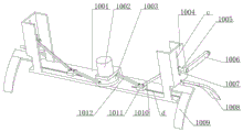
Fig. 1 is a schematic structural diagram of an embodiment of the present invention.
Fig. 2 is a schematic view of the structure of fig. 1 from another angle.
Fig. 3 is a schematic structural view of the support seat 1 in fig. 1.
Fig. 4 is a schematic structural view of the fixing member 2 of fig. 1.
Fig. 5 is a schematic structural view of the grasping assembly 5 in fig. 1.
Fig. 6 is a schematic view of the structure of fig. 5 from another angle.
Fig. 7 is a schematic structural view of the lower support block 509 and the push block 522 in fig. 6.
Fig. 8 is a schematic view of the structure of the gripping assembly 5 gripping the cable roll 4.
Fig. 9 is a schematic structural view of the brake assembly 10 of fig. 1.
Fig. 10 is a schematic view of the structure of fig. 9 from another angle.
Fig. 11 is a schematic view of the structure of fig. 10 with a part omitted from the drawing at another angle.
Fig. 12 is a schematic view of the structure of the height adjusting assembly 11 of fig. 1.
Fig. 13 is a schematic view of the structure of the horizontal adjustment assembly 12 of fig. 1.
Fig. 14 is a schematic structural view of the angle adjusting assembly 13 of fig. 1.
Reference numerals: 1. a supporting seat; 2. a fixing assembly; 201. a stopper; 202. a first connecting plate; 203. a first slide plate; 204. a first spring; 205. a second connecting plate; 3. a carrying rod; 4. a cable winding roller; 5. a grasping assembly; 501. a third connecting plate; 502. a first rack; 503. a gear; 504. a second motor; 505. a second rack; 506. a fourth connecting plate; 507. a first side plate; 508. pushing the plate; 509. a lower support block; 510. a second connecting shaft; 511. a first connecting rod; 512. a third connecting shaft; 513. a second connecting rod; 514. an upper support block; 515. a fifth connecting plate; 516. a second slide plate; 517. a second spring; 518. a first fixing plate; 519. a second side plate; 520. a fourth connecting shaft; 521. a third spring; 522. a push block; 523. a first slider; 524. a second slider; b. a first slide hole; 6. a first connecting shaft; 7. a roller; 8. a first motor; 9. a chassis; 10. a brake assembly; 1001. a first support plate; 1002. a third motor; 1003. a turntable; 1004. a second fixing plate; 1005. a fifth connecting shaft; 1006. a third connecting rod; 1007. a third slider; 1008. a first brake pad; 1009. a second brake pad; 1010. a fourth connecting rod; 1011. a fourth slider; 1012. an eccentric rod; 1013. a fifth connecting rod; 1014. a sixth connecting shaft; 1015. a sixth connecting rod; 1016. a seventh connecting rod; 1017. an eighth connecting rod; 1101. a fourth motor; 1102. a first lead screw; 1103. a second support plate; 1104. an upper chute plate; 1105. a fifth slider; 1106. a lower chute plate; 1107. a ninth connecting rod; 1108. a sixth slider; 1109. an eighth connecting shaft; 1110. a tenth connecting rod; 1111. a seventh slider; e. a fourth slide hole; f. a fifth slide hole; 1018. a seventh connecting shaft; c. a second slide hole; d. a third slide hole; 11. a height adjustment assembly; 12. a level adjustment assembly; 1201. a fifth motor; 1202. a second lead screw; 1203. a third slide plate; 1204. a third support plate; 13. an angle adjustment assembly; 1301. an eighth slider; 1302. an eleventh connecting rod; 1303. a fourth support plate; 1304. a third screw rod; 1305. a sixth motor; 14. a balancing weight; a. a chute.
Detailed Description
In order to make the objects, technical solutions and advantages of the present invention more apparent, the present invention is described in further detail below with reference to the accompanying drawings and embodiments. It should be understood that the specific embodiments described herein are merely illustrative of the invention and are not intended to limit the invention.
As shown in fig. 1 to 3, the AGV-based transfer robot of this embodiment is formed by connecting a support base 1, a fixing component 2, a transfer rod 3, a cable roller 4, a grasping component 5, a first connecting shaft 6, a roller 7, a first motor 8, a chassis 9, a brake component 10, a height adjusting component 11, a horizontal adjusting component 12, an angle adjusting component 13, a counter weight 14, and a chute a.
There are first motor 8 in 9 four corners bottoms of vehicle bottom dish of AGV respectively fixed mounting, first motor 8's output shaft and 6 fixed connection of first connecting axle, the outer circumference fixed mounting of first connecting axle 6 has gyro wheel 7, install balancing weight 14 on the vehicle bottom dish 9, install supporting seat 1 on the balancing weight 14, two altitude mixture control subassemblies 11 of both sides installation on the vehicle bottom dish 9, altitude mixture control subassembly 11 is used for adjusting supporting seat 1 height, horizontal adjustment subassembly 12 is installed to both sides on the supporting seat 1, horizontal adjustment subassembly 12 is used for adjusting the horizontal position of transport pole 3, install angle adjusting subassembly 13 on horizontal adjustment subassembly 12, angle adjusting subassembly 13 is used for adjusting the angle of transport pole 3, be provided with on two transport poles 3 and snatch subassembly 5, it is used for pressing from both sides tight cable winding up roller 4 to snatch subassembly 5.
As shown in fig. 4, the fixing assembly 2 is formed by coupling a stopper 201, a first connecting plate 202, a first sliding plate 203, a first spring 204, and a second connecting plate 205, and the fixing assembly 2 includes: sliding connection has two first slide 203 in the spout a of supporting seat 1, the horizontal plate of two first slide 203 passes through second connecting plate 205 fixed connection, sliding connection has first connecting plate 202 on the vertical plate of first slide 203, be connected through first spring 204 between the horizontal plate of first connecting plate 202 and the horizontal plate of first slide 203, evenly install dog 201 on the vertical plate of first connecting plate 202, be used for fixed transport pole 3 between two adjacent dog 201, fixed subassembly 2 is used for in the transportation, press from both sides tight transport pole 3 between two dog 201, prevent that transport pole 3 from producing in the transportation and rocking.
As shown in fig. 5 to 8, the grasping assembly 5 is formed by coupling a third connecting plate 501, a first rack 502, a gear 503, a second motor 504, a second rack 505, a fourth connecting plate 506, a first side plate 507, a push plate 508, a lower support block 509, a second connecting shaft 510, a first connecting rod 511, a third connecting shaft 512, a second connecting rod 513, an upper support block 514, a fifth connecting plate 515, a second sliding plate 516, a second spring 517, a first fixing plate 518, a second side plate 519, a fourth connecting shaft 520, a third spring 521, a push block 522, a first slider 523, a second slider 524, and a first sliding hole b, and the grasping assembly 5 is: a first fixing plate 518 is fixedly installed between the two carrying rods 3, a third connecting plate 501 and a fourth connecting plate 506 are connected to the first fixing plate 518 through a driving unit in a sliding mode, the moving direction of the third connecting plate 501 is opposite to that of the fourth connecting plate 506, and the third connecting plate 501 and the fourth connecting plate 506 drive the fastening unit to move towards the approaching direction or move towards the far direction simultaneously, so that the cable winding roller 4 can be loosened and grabbed. The driving unit is: a first rack 502 is fixedly mounted on the third connecting plate 501, a second rack 505 is fixedly mounted on the fourth connecting plate 506, a second motor 504 for driving the rotation of the gear 503 is fixedly mounted on the first fixing plate 518, the gear 503 is respectively meshed with the first rack 502 and the second rack 505 for transmission, and the moving direction of the first rack 502 is opposite to that of the second rack 505.
The third connecting plate 501 and the fourth connecting plate 506 are respectively provided with a fastening unit for fixing the cable roller 4, and the fastening units are as follows: the third connecting plate 501 is provided with a push plate 508, the push plate 508 is fixedly provided with an upper supporting block 514, the upper supporting block 514 is contacted with the upper side wall of the inner circumference of the cable roller 4, the upper supporting block 514 is slidably connected with a lower supporting block 509 through a fourth connecting shaft 520, the lower supporting block 509 is contacted with the lower side wall of the inner circumference of the cable roller 4, and the fourth connecting shaft 520 is provided with a third spring 521. A second sliding plate 516 is connected to the third connecting plate 501 in a sliding manner, one end of the second sliding plate 516 is connected to the third connecting plate 501 through a second spring 517, the other end of the second sliding plate 516 is in contact with the outer side wall of the cable winding roll 4, the second sliding plate 516 is fixedly connected to one end of a fifth connecting plate 515, a push block 522 is fixedly mounted at the other end of the fifth connecting plate 515, the inclined surface of the push block 522 is in contact with the inclined surface of a lower support block 509, the fifth connecting plate 515 is rotatably connected to one end of a first connecting rod 511 and one end of a second connecting rod 513 through a third connecting shaft 512, two first sliding holes b are processed at one side of the push plate 508, two first sliding holes b are processed at the other side of the push plate 508, a first sliding block 523 and a second sliding block 524 are respectively slidably connected to the two first sliding holes b, the first sliding block 523 and the second sliding block 524 are fixedly connected to the first sliding block 524 through a second connecting shaft 510, the other end of the first connecting rod 511 is rotatably connected to the second sliding block 510 close to the other end of the second connecting rod 511, the first sliding block 510 is fixedly connected to one side of the second connecting shaft 507, one side of the first connecting plate 519 and one side of the second connecting plate 507, one side of the cable winding roll 4, and one side plate 507 are fixedly connected to one side of the first connecting plate 507, and one side of the cable winding roll 507.
As shown in fig. 9 to 11, a brake assembly 10 is mounted on a chassis 9, and after the transfer robot based on the AGV is transported to a destination, the transfer robot is prevented from moving further by the brake assembly 10, the brake assembly 10 is formed by coupling a first support plate 1001, a third motor 1002, a turntable 1003, a second fixing plate 1004, a fifth connecting shaft 1005, a third connecting shaft 1006, a third slider 1007, a first brake plate 1008, a second brake plate 1009, a fourth connecting shaft 1010, a fourth slider 1011, an eccentric rod 1012, a fifth connecting shaft 1013, a sixth connecting shaft 1014, a sixth connecting shaft 1015, a seventh connecting shaft 1016, an eighth connecting shaft 1017, a seventh connecting shaft 1018, a second sliding hole c, and a third sliding hole d, and the brake assembly 10 is: a first supporting plate 1001 is fixedly mounted on a vehicle chassis 9, a third motor 1002 for driving a rotating disc 1003 to rotate is fixedly mounted on the first supporting plate 1001, two eccentric rods 1012 are rotatably connected to the rotating disc 1003, fourth sliding blocks 1011 are respectively and slidably connected to two third sliding holes d of the first supporting plate 1001, the two eccentric rods 1012 are respectively and rotatably connected to the two fourth sliding blocks 1011, the fourth sliding blocks 1011 are hinged to one ends of fourth connecting rods 1010, second fixing plates 1004 are respectively and fixedly mounted at two ends of the first supporting plate 1001, a third sliding block 1007 is slidably connected to a second sliding hole c of the second fixing plate 1004, a perpendicular bisector of the second sliding hole c is perpendicular to a perpendicular bisector of the third sliding hole d, one side of the third sliding block 1007 is rotatably connected to one end of a third connecting rod 1006, the other end of the third connecting rod 1006 is rotatably connected to a fixing component 2, the other side of the third sliding block 1007 is rotatably connected to a sixth connecting shaft 1014, and the sixth connecting shaft 1014 is fixedly connected to the other end of the fourth connecting rod 1010.
A fifth connecting rod 1013 and a sixth connecting rod 1015 are rotatably connected to the third slider 1007 through a seventh connecting shaft 1018, the fifth connecting rod 1013 is rotatably connected to one end of an eighth connecting rod 1017, a second braking plate 1009 tightly clamped to the outer circumferential surface of the roller 7 is arranged at the other end of the eighth connecting rod 1017, the sixth connecting rod 1015 is rotatably connected to one end of a seventh connecting rod 1016, and a first braking plate 1008 tightly clamped to the outer circumferential surface of the roller 7 is arranged at the other end of the seventh connecting rod 1016.
As shown in fig. 12, the height adjustment assembly 11 is formed by coupling a fourth motor 1101, a first lead screw 1102, a second support plate 1103, an upper chute plate 1104, a fifth slider 1105, a lower chute plate 1106, a ninth connecting rod 1107, a sixth slider 1108, an eighth connecting shaft 1109, a tenth connecting rod 1110, a seventh slider 1111, a fourth sliding hole e, and a fifth sliding hole f, and the height adjustment assembly 11 is: a second supporting plate 1103 is fixedly installed on the chassis 9, a fourth motor 1101 for driving the first lead screw 1102 to rotate is installed on the second supporting plate 1103, the perpendicular bisector of the first lead screw 1102 is perpendicular to the horizontal line, a sixth sliding block 1108 is connected on the first lead screw 1102 in a sliding manner, the sixth sliding block 1108 is connected with a ninth connecting rod 1107 and a tenth connecting rod 1110 in a rotating manner through an eighth connecting shaft 1109, the ninth connecting rod 1107 is connected with the tenth connecting rod 1110 in a crossing manner, lower sliding groove plates 1106 are respectively and fixedly installed on two sides of the chassis 9, seventh sliding blocks 1111 are respectively and slidably connected with fourth sliding holes e of the two lower sliding groove plates 1106, upper sliding groove plates 1104 mutually symmetrical to the lower sliding groove plates 1106 are respectively and fixedly installed on two sides of the lower side surface of the supporting seat 1, fifth sliding holes f of the two upper sliding groove plates 1104 are respectively and slidably connected with fifth sliding blocks 1105, one end of the ninth connecting rod 1110 is hinged with one of the fifth sliding blocks 1105, the other end of the ninth connecting rod 1107 is hinged with one of the seventh sliding blocks 1111, one end of the tenth connecting rod 1110 is hinged with the other fifth sliding blocks 1105, and the other seventh sliding blocks 1111. The height adjustment assembly 11 is used to adjust the height of the carrier bar 3.
As shown in fig. 13, the horizontal adjustment assembly 12 is formed by coupling a fifth motor 1201, a second screw 1202, a third sliding plate 1203, and a third support plate 1204, and the horizontal adjustment assembly 12 is: a third support plate 1204 is fixedly installed on the support seat 1, a fifth motor 1201 for driving the second screw rod 1202 to rotate is fixedly installed on the third support plate 1204, a perpendicular bisector of the second screw rod 1202 is parallel to a horizontal line, a third sliding plate 1203 is slidably connected to the second screw rod 1202, and a carrying rod 3 is arranged on the third sliding plate 1203 through an angle adjusting assembly 13. The horizontal adjustment assembly 12 is used to adjust the horizontal displacement of the carrier bar 3.
As shown in fig. 14, the angle adjusting assembly 13 is formed by coupling an eighth sliding block 1301, an eleventh connecting rod 1302, a fourth supporting plate 1303, a third lead screw 1304, and a sixth motor 1305, and the angle adjusting assembly 13 is: a sixth motor 1305 is fixedly mounted on the fourth supporting plate 1303, an output shaft of the sixth motor 1305 is fixedly connected with a third screw 1304, a perpendicular bisector of the third screw 1304 is parallel to a horizontal line, the sixth motor 1305 is used for driving the third screw 1304 to rotate, an eighth slider 1301 is connected onto the third screw 1304 in a sliding manner, the eighth slider 1301 is connected with one end of an eleventh connecting rod 1302 in a rotating manner, and the other end of the eleventh connecting rod 1302 is connected with a carrying rod 3 in a rotating manner through the eleventh connecting rod 1302. The angle adjusting assembly 13 is used to adjust the angle of the carrier bar 3.
The working principle of the embodiment is as follows: (1) adjusting the height, horizontal displacement and angle of the carrying rod 3: height adjustment of the carrier bar 3: the fourth motor 1101 is started, the fourth motor 1101 drives the first screw 1102 to rotate, the first screw 1102 drives the sixth slider 1108 to move in the vertical direction, the sixth slider 1108 drives the ninth connecting rod 1107 to move through the eighth connecting shaft 1109, one end of the ninth connecting rod 1107 drives one of the fifth sliders 1105 to slide in the fifth sliding hole f of one of the upper sliding chute plates 1104, the other end of the ninth connecting rod 1107 drives one of the seventh sliders 1111 to slide in the fourth sliding hole e of one of the lower sliding chute plates 1106, one end of the tenth connecting rod 1110 drives the other fifth slider 1105 to slide in the fifth sliding hole f of the other upper sliding chute plate 1104, the other end of the tenth connecting rod 1110 drives the other seventh slider 1111 to slide in the fourth sliding hole e of the other lower sliding chute plate 1106, and the height of the carrying rod 3 on the support seat 1 is adjusted through the size of the angle crossed between the ninth connecting rod 1107 and the tenth connecting rod 1110.
Adjusting the horizontal displacement of the carrier bar 3: the fifth motor 1201 is started, the fifth motor 1201 drives the second lead screw 1202 to rotate, the second lead screw 1202 drives the third sliding plate 1203 to move in the horizontal direction, and the third sliding plate 1203 drives the carrying rod 3 to adjust the horizontal displacement of the carrying rod 3.
Adjusting the angle of the carrying rod 3: the sixth motor 1305 is started, the sixth motor 1305 drives the third lead screw 1304 to rotate, the third lead screw 1304 drives the eighth slider 1301 to move in the horizontal direction, and the eighth slider 1301 drives the carrying rod 3 through the eleventh connecting rod 1302 to adjust the angle of the carrying rod 3.
(2) And (3) grabbing and fixing the cable roller 4: after the specific position of the carrying rod 3 is adjusted, the second motor 504 is started, the second motor 504 drives the gear 503 to rotate, the gear 503 drives the third connecting plate 501 and the fourth connecting plate 506 to horizontally move towards the approaching direction through the first rack 502 and the second rack 505, the fastening units on the third connecting plate 501 and the fourth connecting plate 506 move towards the inner side of the cable winding roll 4, the upper supporting block 514 and the two lower supporting blocks 509 are respectively placed inside the cable winding roll 4, the upper supporting block 514 abuts against the upper side wall of the inner circumference of the cable winding roll 4, the third connecting plate 501 drives the second sliding plate 516, the fifth connecting plate 515 and the pushing block 522 to horizontally move in the horizontal moving process, the second sliding plate moves to abut against the outer side wall of the cable winding roll 4, the second sliding plate 516, the fifth connecting plate 515 and the pushing block 522 stop moving, the third connecting plate drives the upper supporting block 514 and the lower supporting block 509 to horizontally move, the abutting block 509 moves to the inclined plane of the lower supporting block 509 and the inclined plane of the pushing block 522, the third connecting plate 501 drives the lower supporting block 509 to horizontally move to abut against the inner circumference of the lower supporting block 509 and prevent the lower supporting block 509 from moving to the inner circumference of the lower supporting roll 4 and prevent the lower supporting block 509 from moving to move to the lower supporting block 509 and to move to the inner circumference of the lower supporting block 4.
In the process that the push plate 508 continues to move horizontally near the cable winding roller 4, the push plate 508 drives the two first sliders 523 and the second slider 524 on one side to slide in the two first sliding holes b on one side of the push plate 508, the first slider 523 and the second slider 524 on one side drive the first side plate 507 to be clamped with the outer side wall of the cable winding roller 4, the push plate 508 drives the other two first sliders 523 and the second slider 524 to respectively slide in the other two first sliding holes b of the push plate 508, and the first slider 523 and the second slider 524 on the other side drive the second side plate 519 to be clamped with the outer side wall of the cable winding roller 4.
In sum, the upper supporting block 514 and the lower supporting block 509 are respectively supported on the inner side wall of the cable roller 4, and the first side plate 507 and the second side plate 519 are fixed on the outer side wall of the cable roller 4 for preventing the rolling phenomenon of the cable roller 4 in the carrying process of the cable roller 4.
(3) Braking: in the transfer robot transportation based on AGV, press from both sides tight haulage pole 3 between two dogs 201, prevent that haulage pole 3 from producing in the transportation and rocking. After the transfer robot based on the AGV is transported to a destination, the third motor 1002 is started, the third motor 1002 drives the turntable 1003 to rotate, the turntable 1003 drives the fourth slider 1011 to slide in the third sliding hole d of the first supporting plate 1001 through the eccentric rod 1012, the fourth slider 1011 drives the third slider 1007 to slide in the second sliding hole c of the second fixing plate 1004 through the sixth connecting shaft 1014, the third slider 1007 drives the fifth connecting rod 1013 and the sixth connecting rod 1015 to rotate through the seventh connecting shaft 1018, the fifth connecting rod 1013 drives the second brake plate 1009 to clamp the roller 7 through the eighth connecting rod 1017, the sixth connecting rod 1015 drives the first brake plate 1008 to clamp the roller 7 through the seventh connecting rod 1016, and the second brake plate 1009 and the first brake plate 1008 are used for preventing the roller 7 from rolling. The third slider 1007 drives the first sliding plate 203 to slide in the chute a on the supporting seat 1 through the fifth connecting shaft 1005 and the third connecting rod 1006 in the vertical direction movement process, the two stoppers 201 are separated from the carrying rod 3, the grabbing component 5 and the cable winding roll 4 are loosened according to the principle of (2), and the cable winding roll 4 is placed at a transportation destination.
The above description is only a preferred embodiment of the present invention, and is not intended to limit the scope of the present invention.
Claims (7)
1. The utility model provides a transfer robot based on AGV, is provided with first motor (8) respectively in chassis (9) four corners bottom of AGV, the output shaft and first connecting axle (6) fixed connection of first motor (8), and the outer circumference of first connecting axle (6) is provided with gyro wheel (7), its characterized in that: a balancing weight (14) is arranged on the vehicle chassis (9), a supporting seat (1) is arranged on the balancing weight (14), two height adjusting components (11) for adjusting the height of the supporting seat (1) are arranged on two sides of the vehicle chassis (9), carrying rods (3) are respectively arranged on two sides of the supporting seat (1) through two horizontal adjusting components (12), an angle adjusting component (13) for adjusting the carrying rods (3) is arranged on the horizontal adjusting components (12), and a grabbing component (5) for clamping a cable winding roller (4) is arranged on the two carrying rods (3);
the grabbing component (5) comprises: a first fixing plate (518) is fixedly installed between the two carrying rods (3), a third connecting plate (501) and a fourth connecting plate (506) are connected to the first fixing plate (518) in a sliding mode through a driving unit, the moving direction of the third connecting plate (501) is opposite to that of the fourth connecting plate (506), and fastening units for fixing the cable winding roller (4) are respectively arranged on the third connecting plate (501) and the fourth connecting plate (506);
the fastening unit is as follows: a push plate (508) is arranged on the third connecting plate (501), an upper supporting block (514) which is in contact with the upper side wall of the inner circumference of the cable roller (4) is arranged on the push plate (508), the upper supporting block (514) is in sliding connection with a lower supporting block (509) through a fourth connecting shaft (520), the lower supporting block (509) is in contact with the lower side wall of the inner circumference of the cable roller (4), and a third spring (521) is arranged on the fourth connecting shaft (520);
a second sliding plate (516) is connected with the third connecting plate (501) in a sliding manner, one end of the second sliding plate (516) is connected with the third connecting plate (501) through a second spring (517), the other end of the second sliding plate (516) is contacted with the outer side wall of the cable winding roller (4), the second sliding plate (516) is fixedly connected with one end of a fifth connecting plate (515), a push block (522) is arranged at the other end of the fifth connecting plate (515), the inclined surface of the push block (522) is contacted with the inclined surface of a lower support block (509), the fifth connecting plate (515) is respectively and rotatably connected with one end of a first connecting rod (511) and one end of a second connecting rod (513) through a third connecting shaft (512), two first sliding holes (b) are respectively processed at two sides of the push plate (508), two first sliding holes (b) are internally and respectively connected with a first sliding block (523) and a second sliding block (524) in a sliding manner, the first sliding blocks (523) and the second sliding blocks (524) on two sides are connected through a second connecting shaft (510), the other end of a first connecting rod (511) is rotatably connected with the second connecting shaft (510) on one side, the other end of a second connecting rod (513) is rotatably connected with the second connecting shaft (510) on the other side, a first side plate (507) is fixedly installed on the first sliding block (523) and the second sliding block (524) on one side, and a second side plate (519) is fixedly installed on the first sliding block (523) and the second sliding block (524) on the other side ) The push plate (508) is in contact with one end of the cable roller (4), and the first side plate (507) and the second side plate (519) are in contact with the outer side wall of the cable roller (4) respectively.
2. An AGV-based transfer robot as claimed in claim 1, wherein said drive unit is: a first rack (502) is arranged on the third connecting plate (501), a second rack (505) is arranged on the fourth connecting plate (506), a second motor (504) for driving a gear (503) to rotate is arranged on the first fixing plate (518), the gear (503) is respectively in meshing transmission with the first rack (502) and the second rack (505), and the moving direction of the first rack (502) is opposite to the moving direction of the second rack (505).
3. The AGV-based transfer robot of claim 1, wherein the chassis (9) is provided with a brake assembly (10), and the brake assembly (10) is: a first supporting plate (1001) is arranged on a vehicle chassis (9), the first supporting plate (1001) is provided with a third motor (1002) for driving a rotating disc (1003) to rotate, the rotating disc (1003) is rotatably connected with two eccentric rods (1012), two third sliding holes (d) in the first supporting plate (1001) are respectively and slidably connected with a fourth sliding block (1011), the two eccentric rods (1012) are respectively and rotatably connected with the two fourth sliding blocks (1011), the fourth sliding block (1011) is hinged with one end of a fourth connecting rod (1010), two ends of the first supporting plate (1001) are respectively provided with a second fixing plate (1004), a second sliding hole (c) in the second fixing plate (1004) is slidably connected with a third sliding block (1007), one side of the third sliding block (1007) is rotatably connected with one end of the third connecting rod (1006) through a fifth connecting shaft (1005), the other end of the third connecting rod (1006) is rotatably connected with a fixing component (2), the other side of the third sliding block (1007) is rotatably connected with a sixth connecting shaft (1014), and the sixth connecting shaft (1005) is fixedly connected with the other end of the fourth connecting rod (1010);
the third sliding block (1007) is rotatably connected with a fifth connecting rod (1013) and a sixth connecting rod (1015) through a seventh connecting shaft (1018), the fifth connecting rod (1013) is rotatably connected with one end of an eighth connecting rod (1017), the other end of the eighth connecting rod (1017) is provided with a second brake plate (1009) clamped with the outer circumferential surface of the roller (7), the sixth connecting rod (1015) is rotatably connected with one end of a seventh connecting rod (1016), and the other end of the seventh connecting rod (1016) is provided with a first brake plate (1008) clamped with the outer circumferential surface of the roller (7).
4. An AGV-based transfer robot according to claim 3, characterized in that said fixed assembly (2) is: sliding connection has two first slide (203) in spout (a) of supporting seat (1), the horizontal plate of two first slide (203) passes through second connecting plate (205) fixed connection, sliding connection has first connecting plate (202) on the vertical plate of first slide (203), be connected through first spring (204) between the horizontal plate of first connecting plate (202) and the horizontal plate of first slide (203), evenly be provided with dog (201) on the vertical plate of first connecting plate (202), be used for fixed transport pole (3) between two adjacent dog (201).
5. An AGV-based transfer robot according to claim 1, characterized in that said height adjustment assembly (11) is: a fourth motor (1101) for driving a first lead screw (1102) to rotate is arranged on a second supporting plate (1103) on a vehicle chassis (9), a sixth sliding block (1108) is connected on the first lead screw (1102) in a sliding manner, the sixth sliding block (1108) is connected with a ninth connecting rod (1107) and a tenth connecting rod (1110) which are connected in a cross manner through an eighth connecting shaft (1109) in a rotating manner, lower sliding chute plates (1106) are fixedly arranged on the two sides of the upper side of the vehicle chassis (9) respectively, seventh sliding blocks (1111) are connected with fourth sliding holes (e) of the two lower sliding chute plates (1106) in a sliding manner respectively, upper sliding chute plates (1104) which are mutually symmetrical to the lower sliding chute plates (1106) are fixedly arranged on the two sides of the lower side surface of the supporting seat (1) respectively, fifth sliding holes (f) of the two upper sliding chute plates (1104) are respectively connected with fifth sliding blocks (1105) in a sliding manner, one end of the ninth connecting rod (1107) is hinged to one of the fifth sliding blocks (1105), the other sliding blocks (1111), the other end of the seventh sliding blocks (1111) is hinged to one end, one of the tenth connecting rod (1110) is hinged to the other fifth sliding blocks (1105), and the seventh sliding blocks (1111) is hinged to the other end of the tenth connecting rod (1111).
6. An AGV-based transfer robot according to claim 1, wherein said level adjustment assembly (12) is: a third supporting plate (1204) on the supporting seat (1) is provided with a fifth motor (1201) for driving the second screw rod (1202) to rotate, a third sliding plate (1203) is connected onto the second screw rod (1202) in a sliding mode, and a carrying rod (3) is arranged on the third sliding plate (1203) through an angle adjusting assembly (13).
7. An AGV-based transfer robot according to claim 1 or 6, characterized in that said angle adjustment assembly (13) is: a sixth motor (1305) for driving the third screw rod (1304) to rotate is arranged on the fourth supporting plate (1303), an eighth sliding block (1301) is connected onto the third screw rod (1304) in a sliding mode, the eighth sliding block (1301) is connected with one end of an eleventh connecting rod (1302) in a rotating mode, and the other end of the eleventh connecting rod (1302) is connected with a carrying rod (3) in a rotating mode through the eleventh connecting rod (1302).
Priority Applications (1)
| Application Number | Priority Date | Filing Date | Title |
|---|---|---|---|
| CN202210537988.XA CN114803354B (en) | 2022-05-18 | 2022-05-18 | Transfer robot based on AGV |
Applications Claiming Priority (1)
| Application Number | Priority Date | Filing Date | Title |
|---|---|---|---|
| CN202210537988.XA CN114803354B (en) | 2022-05-18 | 2022-05-18 | Transfer robot based on AGV |
Publications (2)
| Publication Number | Publication Date |
|---|---|
| CN114803354A CN114803354A (en) | 2022-07-29 |
| CN114803354B true CN114803354B (en) | 2023-03-17 |
Family
ID=82515760
Family Applications (1)
| Application Number | Title | Priority Date | Filing Date |
|---|---|---|---|
| CN202210537988.XA Active CN114803354B (en) | 2022-05-18 | 2022-05-18 | Transfer robot based on AGV |
Country Status (1)
| Country | Link |
|---|---|
| CN (1) | CN114803354B (en) |
Family Cites Families (10)
| Publication number | Priority date | Publication date | Assignee | Title |
|---|---|---|---|---|
| JP2007054914A (en) * | 2005-08-24 | 2007-03-08 | Mitsui High Tec Inc | Handling tool |
| CN106081882A (en) * | 2016-08-26 | 2016-11-09 | 李晓敏 | A kind of transport cable construction car |
| CN110844427A (en) * | 2019-11-07 | 2020-02-28 | 黄娉 | Safe and reliable intelligent transfer robot for warehouse logistics |
| CN213949867U (en) * | 2020-10-20 | 2021-08-13 | 科德汽车零部件(长春)有限公司 | Device of transport in coordination |
| CN214081447U (en) * | 2020-10-21 | 2021-08-31 | 苏州科美格科技有限公司 | Novel cable drum transfer robot |
| CN112279159A (en) * | 2020-10-27 | 2021-01-29 | 罗仁华 | Fork truck handling device that stability is high |
| CN213595809U (en) * | 2020-11-16 | 2021-07-02 | 咸宁市咸安区电宏水泥制杆有限公司 | A handling device for cement pipe removes |
| CN214731717U (en) * | 2020-12-29 | 2021-11-16 | 上海黄工印刷有限公司 | Adjustable roll film carrying device |
| CN215789959U (en) * | 2021-09-11 | 2022-02-11 | 美尔森碳制品(上海)有限公司 | Manipulator convenient to maintenance is dismantled |
| CN215665854U (en) * | 2021-09-27 | 2022-01-28 | 深圳市鑫申新材料科技有限公司 | Double-arm multifunctional manipulator for stacking high-strength aluminum alloy ingots |
-
2022
- 2022-05-18 CN CN202210537988.XA patent/CN114803354B/en active Active
Also Published As
| Publication number | Publication date |
|---|---|
| CN114803354A (en) | 2022-07-29 |
Similar Documents
| Publication | Publication Date | Title |
|---|---|---|
| EP3842605B1 (en) | Intelligent parking lot and cluster transport robot thereof | |
| CN201106302Y (en) | Intelligent vehicle access conveying device | |
| CN112282459B (en) | AGV intelligent transfer robot for stereo parking garage and working method thereof | |
| CN110758038A (en) | Novel AGV drive chassis of floating | |
| CN108729706A (en) | A kind of AisleStack parking house for bicycles | |
| CN114803354B (en) | Transfer robot based on AGV | |
| CN109941686B (en) | Coating production line and translation car | |
| JP5526390B2 (en) | Carriage type transfer device and steering control method thereof | |
| CN116742512A (en) | Handcart type circuit breaker transferring platform and circuit breaker detection method | |
| CN214651392U (en) | Skip moves and carries mechanism, automatic traditional thread binding putting in and out of skip | |
| CN214942896U (en) | Automobile clamping wheel type transfer robot | |
| CN210064777U (en) | Automatic transfer system for crown block and suspension type package transfer trolley with packages | |
| CN210086946U (en) | Modularization sideslip platform truck | |
| CN112551073A (en) | Skip moves and carries mechanism, automatic traditional thread binding putting in and out of skip | |
| CN111891668A (en) | Monorail conveying system | |
| CN207332403U (en) | Multi-storied garage multistage wheelbase self-adapting type conveyor-type position in storehouse equipment | |
| CN112297989A (en) | Backpack wheel set transfer trolley and transfer method | |
| CN221609653U (en) | Holding clamp type AGV carrying trolley robot and parking equipment | |
| CN206128759U (en) | Roller -type car sideslip carrier | |
| CN201753188U (en) | Device for transporting and positioning large parts | |
| CN215401245U (en) | AGV dolly return to well device | |
| CN218230605U (en) | Air transport trolley in clean environment | |
| CN221274187U (en) | Three-dimensional warehouse transportation system for building material construction | |
| CN219057565U (en) | Container wheel transportation device | |
| CN219487410U (en) | Intelligent transport vehicle with turning plate mechanism and intelligent parking system |
Legal Events
| Date | Code | Title | Description |
|---|---|---|---|
| PB01 | Publication | ||
| PB01 | Publication | ||
| SE01 | Entry into force of request for substantive examination | ||
| SE01 | Entry into force of request for substantive examination | ||
| GR01 | Patent grant | ||
| GR01 | Patent grant |