CN114800888B - Perforating device for building construction and perforating method thereof - Google Patents
Perforating device for building construction and perforating method thereof Download PDFInfo
- Publication number
- CN114800888B CN114800888B CN202210638171.1A CN202210638171A CN114800888B CN 114800888 B CN114800888 B CN 114800888B CN 202210638171 A CN202210638171 A CN 202210638171A CN 114800888 B CN114800888 B CN 114800888B
- Authority
- CN
- China
- Prior art keywords
- dust
- shell
- compression
- air
- filter
- Prior art date
- Legal status (The legal status is an assumption and is not a legal conclusion. Google has not performed a legal analysis and makes no representation as to the accuracy of the status listed.)
- Active
Links
Images

Classifications
-
- B—PERFORMING OPERATIONS; TRANSPORTING
- B28—WORKING CEMENT, CLAY, OR STONE
- B28D—WORKING STONE OR STONE-LIKE MATERIALS
- B28D1/00—Working stone or stone-like materials, e.g. brick, concrete or glass, not provided for elsewhere; Machines, devices, tools therefor
- B28D1/14—Working stone or stone-like materials, e.g. brick, concrete or glass, not provided for elsewhere; Machines, devices, tools therefor by boring or drilling
- B28D1/146—Tools therefor
-
- B—PERFORMING OPERATIONS; TRANSPORTING
- B28—WORKING CEMENT, CLAY, OR STONE
- B28D—WORKING STONE OR STONE-LIKE MATERIALS
- B28D7/00—Accessories specially adapted for use with machines or devices of the preceding groups
- B28D7/02—Accessories specially adapted for use with machines or devices of the preceding groups for removing or laying dust, e.g. by spraying liquids; for cooling work
-
- Y—GENERAL TAGGING OF NEW TECHNOLOGICAL DEVELOPMENTS; GENERAL TAGGING OF CROSS-SECTIONAL TECHNOLOGIES SPANNING OVER SEVERAL SECTIONS OF THE IPC; TECHNICAL SUBJECTS COVERED BY FORMER USPC CROSS-REFERENCE ART COLLECTIONS [XRACs] AND DIGESTS
- Y02—TECHNOLOGIES OR APPLICATIONS FOR MITIGATION OR ADAPTATION AGAINST CLIMATE CHANGE
- Y02A—TECHNOLOGIES FOR ADAPTATION TO CLIMATE CHANGE
- Y02A50/00—TECHNOLOGIES FOR ADAPTATION TO CLIMATE CHANGE in human health protection, e.g. against extreme weather
- Y02A50/20—Air quality improvement or preservation, e.g. vehicle emission control or emission reduction by using catalytic converters
- Y02A50/2351—Atmospheric particulate matter [PM], e.g. carbon smoke microparticles, smog, aerosol particles, dust
Abstract
The invention relates to a perforating device for building construction, comprising: the drilling mechanism comprises a drilling machine for drilling and a dust cover for preventing dust from drifting, and the drilling machine is arranged in the dust cover; an air extractor; the dust removing mechanism comprises a filter cylinder for filtering dust and a compression cylinder for compressing the dust; the punching mechanism is connected with the dust removing mechanism through the air extractor, and the air extractor conveys dust in the punching mechanism into the dust removing mechanism for filtering and removing dust. The beneficial effects of the invention are as follows: when the drilling machine punches, the dust cover can effectively wrap dust in, prevent that the dust from drifting everywhere, and the air extractor sucks the dust into dust removal mechanism simultaneously and collects to the dust extrusion after will collecting makes it inseparabler, thereby the effectual volume that has improved the interior dust collection of compression section of thick bamboo has increased the volume of compression section of thick bamboo.
Description
Technical Field
The invention relates to the technical field of building construction, in particular to a punching device and a punching method for building construction.
Background
The wall surface can be perforated during building construction and decoration, but a large amount of dust and scraps can be generated during perforation.
Chinese patent CN110509440B discloses a dust-free wall puncher for interior decoration, comprising a machine body, wherein an adjusting device for adjusting the punching depth is arranged on the periphery of the machine body; the adjusting device comprises measuring blocks which are vertically symmetrically arranged on the upper side and the lower side of the machine body, a moving cavity is formed in one side face of each measuring block, a spring cavity is arranged in the inner wall of the machine body and far away from the moving cavity, a transverse sliding chute is arranged in the inner wall of the moving cavity and far away from the spring cavity, a T-shaped sliding block fixedly connected with one side face of the machine body is connected between the moving cavity and the spring cavity in a sliding manner, a powerful spring is connected between the T-shaped sliding block and the spring cavity, each of the left side wall and the right side wall of the transverse sliding chute and the right side face of each measuring block are respectively connected with an adjusting screw in a rotating manner, a knob is fixedly arranged on the right side of each adjusting screw, and a distance measuring sliding block is connected to the adjusting screw in a threaded manner, and a rubber cushion is fixedly connected between the measuring blocks.
The dust that above-mentioned patent produced can be collected the drilling to make the dust can not overflow out, but the dust volume that its can collect is very limited, will be packed after using a section time, just can continue to use after need clear up, work efficiency is lower, uses inconveniently.
Disclosure of Invention
Aiming at the defects of the prior art, the invention aims to provide a punching device for building construction and a punching method thereof so as to solve the problems.
The technical scheme of the invention is realized as follows: a perforating device for construction, comprising:
the drilling mechanism comprises a drilling machine for drilling and a dust cover for preventing dust from drifting, and the drilling machine is arranged in the dust cover;
an air extractor;
the dust removing mechanism comprises a filter cylinder for filtering dust and a compression cylinder for compressing the dust;
the punching mechanism is connected with the dust removing mechanism through the air extractor, and the air extractor conveys dust in the punching mechanism into the dust removing mechanism for filtering and removing dust.
Through adopting above-mentioned technical scheme, the rig is when punching, and the dust cover can effectually wrap up the dust in, prevents that the dust from drifting everywhere, and the air exhauster is collected in inhaling dust collection mechanism simultaneously to the dust extrusion after will collecting makes it inseparabler, thereby the effectual volume that has improved the interior dust collection of compression section of thick bamboo has increased the volume of compression section of thick bamboo.
The invention is further provided with: the punching mechanism further includes:
the two ends of the shell are arranged in a penetrating way;
the drilling machine is fixedly arranged at the center of the shell through connecting ribs, two ends of the shell are respectively connected with the dust cover and the air extractor, a gap between the outer wall of the drilling machine and the inner wall of the shell is provided with a flow channel for dust to flow, and the section of the flow channel is annular.
Through adopting above-mentioned technical scheme, the flow channel that annular set up can effectually improve the adsorption efficiency to the dust, makes its absorbing effect better to the air that flows in the flow channel can effectually help the rig dispel the heat, prolongs the life of rig.
The invention is further provided with: the dust cover includes:
a bellows;
the side wall of the air inlet pipe is provided with a plurality of first air inlets in the circumferential direction;
one end of the air inlet pipe is connected with one end of the corrugated pipe, far away from the air inlet pipe, is connected with the shell, a drill bit of the drilling machine is arranged in the corrugated pipe, and a central shaft of the drill bit coincides with a central shaft of the dust cover.
Through adopting above-mentioned technical scheme, when punching, thereby promote the rig towards the wall and compress the bellows to make drill bit and wall contact punch, during the air exhauster work, outside air enters into the dust cover from first air inlet, and the air current that outside got into can effectually drive the dust that produces when punching, thereby sends the dust into dust removal mechanism in.
The invention is further provided with: the punching mechanism further includes:
the handle is fixedly arranged on the outer wall of the shell.
Through adopting above-mentioned technical scheme, make the operation to punching machine constructs more convenient, light through the handle.
The invention is further provided with: the filter cartridge includes:
the filter comprises a filter shell, wherein an air outlet is formed in the top end of the filter shell, a second air inlet is formed in the side wall of the filter shell, the second air inlet is formed in the tangential direction of the side wall of the filter shell, and a dust outlet is formed in the lower end of the filter shell;
a filter screen;
the filter screen is arranged in the filter shell and connected with the air outlet, and the air extractor is connected with the second air inlet.
Through adopting above-mentioned technical scheme, the gas that contains the dust is sent into the filtration shell through the second air inlet, is carrying out the heliciform along the inner wall of filtration shell and flows, makes dust and air separation, and the dust descends and enters into the compression section of thick bamboo through the dirt outlet, and the air is discharged from the gas outlet through the filtration of filter screen, effectually separates dust and air to make exhaust air keep clean.
The invention is further provided with: the compression cylinder includes:
the upper end of the compression shell is provided with an opening;
a central shaft provided at the center of the inside of the compression casing;
the rotating shaft is rotationally connected to the central shaft;
a baffle plate fixed between the central shaft and the inner wall of the compression casing;
the rotating plate is rotationally connected between the central shaft and the inner wall of the compression shell;
the driving device can rotate forwards and backwards;
the inside of the filter shell is communicated with the inside of the compression shell through the dust outlet, one side of the rotating plate is fixed on the rotating shaft, and the driving device is connected with the rotating shaft.
Through adopting above-mentioned technical scheme, the dust gets into and stores in the compression shell, and the periodic drive rotation board of drive arrangement uses the axis of rotation to carry out forward and reverse rotation as the axle center, promotes the both sides of baffle with the dust in the compression shell, makes the dust compression on the both sides of baffle to the effectual capacity of storing of dust in the compression shell that has improved.
The invention is further provided with: the compression cylinder further comprises:
and the scraping blade is arranged on the edge of the rotating plate and is in abutting connection with the inner wall of the compression shell.
Through adopting above-mentioned technical scheme, the doctor-bar can effectually hang down the dust on the compression shell inner wall and collect the extrusion, makes the collection effect to the dust better, and the clearance is cleaner.
The invention is further provided with: the cartridge filter is established in the top of compression section of thick bamboo, can dismantle the connection between cartridge filter and the compression section of thick bamboo.
Through adopting above-mentioned technical scheme, when the dust in the compression section of thick bamboo is collected certain degree and is cleared up, can take out the compression section of thick bamboo with dust discharge can.
The invention is further provided with: the dust outlet is far away from the baffle.
Through adopting above-mentioned technical scheme, can effectual increase dust collection's capacity, can also make the convenient inflow of dust in compressing the shell.
A punching method of a punching device for building construction comprises the following steps:
s1: the handle is held, the air inlet pipe is propped against the wall surface needing to be perforated, the drill bit is aligned to the perforation point, and the air extractor is started to enable outside air to enter the dust cover through the first air inlet;
s2: starting the drilling machine to enable the drill bit to gradually approach the wall surface to punch the wall surface, compressing the corrugated pipe gradually, and sucking dust generated during punching into the dust removing mechanism through the flow channel;
s3: meanwhile, the air flowing in the flow channel dissipates heat of the drilling machine;
s4: the gas containing dust is sent into the filter shell through the second air inlet, flows in a spiral manner along the inner wall of the filter shell, so that the dust is separated from air, the dust falls into the compression cylinder through the dust outlet, and the air is discharged from the air outlet through the filtration of the filter screen;
s5: the dust enters and is stored in the compression shell, the driving device periodically drives the rotating plate to rotate forwards and backwards by taking the rotating shaft as the axis, the dust in the compression shell is pushed to the two sides of the baffle, and the dust is compressed on the two sides of the baffle;
s6: after a period of use, the compression cylinder can be taken down to pour out the compressed dust.
Through adopting above-mentioned technical scheme, can effectually collect and extrude the dust that produces when punching, make its volume that can collect the dust bigger, the operational environment of fine protection and workman's healthy.
Drawings
In order to more clearly illustrate the embodiments of the invention or the technical solutions of the prior art, the drawings which are used in the description of the embodiments or the prior art will be briefly described, it being obvious that the drawings in the description below are only some embodiments of the invention, and that other drawings can be obtained according to these drawings without inventive faculty for a person skilled in the art.
FIG. 1 is a schematic structural diagram of an embodiment of the present invention.
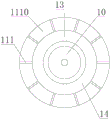
Fig. 2 is a left side view of the structure of the punching mechanism according to the embodiment of the present invention.
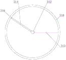
Fig. 3 is a top view of a compression cylinder in accordance with an embodiment of the present invention.
Detailed Description
The following description of the embodiments of the present invention will be made clearly and completely with reference to the accompanying drawings, in which it is apparent that the embodiments described are only some embodiments of the present invention, but not all embodiments. All other embodiments, which can be made by those skilled in the art based on the embodiments of the invention without making any inventive effort, are intended to be within the scope of the invention.
As shown in fig. 1 to 3, the present invention discloses a punching device for building construction, comprising:
a punching mechanism 1, wherein the punching mechanism 1 comprises a drilling machine 10 for punching and a dust cover 11 for preventing dust from drifting, and the drilling machine 10 is arranged in the dust cover 11;
an air extractor 2;
a dust removing mechanism 3, the dust removing mechanism 3 including a filter cartridge 30 for filtering dust, a compression cartridge 31 for compressing dust;
the punching mechanism 1 is connected with the dust removing mechanism 3 through the air extractor 2, and the air extractor 2 conveys dust in the punching mechanism 1 into the dust removing mechanism 3 for filtering and dust removing.
Through adopting above-mentioned technical scheme, the rig is when punching, and the dust cover can effectually wrap up the dust in, prevents that the dust from drifting everywhere, and the air exhauster is collected in inhaling dust collection mechanism simultaneously to the dust extrusion after will collecting makes it inseparabler, thereby the effectual volume that has improved the interior dust collection of compression section of thick bamboo has increased the volume of compression section of thick bamboo.
In an embodiment of the present invention, the punching mechanism 1 further includes:
the shell 12, the both ends of the said shell 12 set up transparently;
the drilling machine 10 is fixedly arranged in the center of the shell 12 through a connecting rib 13, two ends of the shell 12 are respectively connected with the dust cover 11 and the air extractor 2, a gap between the outer wall of the drilling machine 10 and the inner wall of the shell 12 is provided with a flow channel 14 for dust to flow, and the section of the flow channel 14 is annular.
Through adopting above-mentioned technical scheme, the flow channel that annular set up can effectually improve the adsorption efficiency to the dust, makes its absorbing effect better to the air that flows in the flow channel can effectually help the rig dispel the heat, prolongs the life of rig.
In the embodiment of the present invention, the dust cover 11 includes:
a bellows 110;
an intake pipe 111, a plurality of first intake ports 1110 are circumferentially provided on a side wall of the intake pipe 111;
one end of the air inlet pipe 111 is connected with one end of the corrugated pipe 110, one end of the corrugated pipe 110 away from the air inlet pipe 111 is connected with the shell 12, the drill bit 100 of the drilling machine 10 is arranged in the corrugated pipe 110, and the central axis of the drill bit 100 coincides with the central axis of the dust cover 11.
Through adopting above-mentioned technical scheme, when punching, thereby promote the rig towards the wall and compress the bellows to make drill bit and wall contact punch, during the air exhauster work, outside air enters into the dust cover from first air inlet, and the air current that outside got into can effectually drive the dust that produces when punching, thereby sends the dust into dust removal mechanism in.
In an embodiment of the present invention, the punching mechanism 1 further includes:
a handle 15, said handle 15 being fixedly mounted on the outer wall of the housing 12.
Through adopting above-mentioned technical scheme, make the operation to punching machine constructs more convenient, light through the handle.
In an embodiment of the present invention, the filter cartridge 30 includes:
the filter comprises a filter housing 300, wherein an air outlet 301 is formed in the top end of the filter housing 300, a second air inlet 302 is formed in the side wall of the filter housing 300, the second air inlet 302 is formed along the tangential direction of the side wall of the filter housing 300, and a dust outlet 303 is formed in the lower end of the filter housing 300;
a filter screen 304;
wherein, the filter screen 304 is arranged in the filter housing 300 and connected with the air outlet 301, and the air extractor 2 is connected with the second air inlet 302.
Through adopting above-mentioned technical scheme, the gas that contains the dust is sent into the filtration shell through the second air inlet, is carrying out the heliciform along the inner wall of filtration shell and flows, makes dust and air separation, and the dust descends and enters into the compression section of thick bamboo through the dirt outlet, and the air is discharged from the gas outlet through the filtration of filter screen, effectually separates dust and air to make exhaust air keep clean.
In the embodiment of the present invention, the compression cylinder 31 includes:
a compression housing 310, an upper end of the compression housing 310 being provided with an opening;
a central shaft 311, the central shaft 311 being provided at the center of the inside of the compression casing 310;
a rotation shaft 312, the rotation shaft 312 being rotatably connected to the central shaft 311;
a baffle 313, the baffle 313 being fixed between the central shaft 311 and an inner wall of the compression casing 310;
a rotation plate 314 rotatably coupled between the central shaft 311 and the inner wall of the compression casing 310;
a driving device 315, wherein the driving device 315 can rotate in the forward direction and the reverse direction;
wherein, the inside of the filter housing 300 is communicated with the inside of the compression housing 310 through the dust outlet 303, one side of the rotating plate 314 is fixed on the rotating shaft 312, and the driving device 315 is connected with the rotating shaft 312.
Through adopting above-mentioned technical scheme, the dust gets into and stores in the compression shell, and the periodic drive rotation board of drive arrangement uses the axis of rotation to carry out forward and reverse rotation as the axle center, promotes the both sides of baffle with the dust in the compression shell, makes the dust compression on the both sides of baffle to the effectual capacity of storing of dust in the compression shell that has improved.
In the embodiment of the present invention, the compression cylinder 31 further includes:
a wiper 316, the wiper 316 being provided on the edge of the rotating plate 314, the wiper 316 being in interference connection with the inner wall of the compression housing 310.
Through adopting above-mentioned technical scheme, the doctor-bar can effectually hang down the dust on the compression shell inner wall and collect the extrusion, makes the collection effect to the dust better, and the clearance is cleaner.
In the embodiment of the present invention, the filter cartridge 30 is disposed above the compression cylinder 31, and the filter cartridge 30 is detachably connected to the compression cylinder 31.
Through adopting above-mentioned technical scheme, when the dust in the compression section of thick bamboo is collected certain degree and is cleared up, can take out the compression section of thick bamboo with dust discharge can.
In the embodiment of the present invention, the dust outlet 303 is disposed away from the baffle 313.
Through adopting above-mentioned technical scheme, can effectual increase dust collection's capacity, can also make the convenient inflow of dust in compressing the shell.
A punching method of a punching device for building construction comprises the following steps:
s1: holding the handle 15, pressing the air inlet pipe 111 against the wall surface to be perforated, aligning the drill bit 100 with the perforation point, and starting the air extractor to enable external air to enter the dust cover 11 through the first air inlet 1110;
s2: starting the drilling machine 10 to enable the drill bit 100 to gradually approach the wall surface to punch the wall surface, compressing the corrugated pipe 110 gradually, and sucking dust generated during punching into the dust removing mechanism 3 through the flow channel 14;
s3: simultaneously, the air flowing in the flow channel 14 dissipates heat of the drilling machine 10;
s4: the gas containing dust is sent into the filter housing 300 through the second gas inlet 302, flows in a spiral shape along the inner wall of the filter housing 300, separates the dust from air, descends into the compression cylinder 31 through the dust outlet 303, and is discharged from the gas outlet 301 through the filtration of the filter screen 304;
s5: the dust enters and is stored in the compression shell 310, the driving device 315 periodically drives the rotating plate 314 to rotate forward and backward by taking the rotating shaft 312 as the axis, the dust in the compression shell 310 is pushed to the two sides of the baffle 313, and the dust is compressed on the two sides of the baffle 313;
s6: after a period of use, the compression cylinder 31 can be removed to pour out the compressed dust.
Through adopting above-mentioned technical scheme, can effectually collect and extrude the dust that produces when punching, make its volume that can collect the dust bigger, the operational environment of fine protection and workman's healthy.
The foregoing description of the preferred embodiments of the invention is not intended to be limiting, but rather is intended to cover all modifications, equivalents, alternatives, and improvements that fall within the spirit and scope of the invention.
Claims (2)
1. Perforating device for construction, characterized by including:
the drilling mechanism (1) comprises a drilling machine (10) for drilling and a dust cover (11) for preventing dust from drifting, wherein the drilling machine (10) is arranged in the dust cover (11);
an air extractor (2);
a dust removing mechanism (3), wherein the dust removing mechanism (3) comprises a filter cylinder (30) for filtering dust and a compression cylinder (31) for compressing dust;
the punching mechanism (1) is connected with the dust removing mechanism (3) through the air extractor (2), and the air extractor (2) conveys dust in the punching mechanism (1) into the dust removing mechanism (3) for filtering and dust removing;
the punching mechanism (1) further comprises:
the shell (12), both ends of the said shell (12) penetrate and set up;
the drilling machine (10) is fixedly arranged at the center of the shell (12) through a connecting rib (13), two ends of the shell (12) are respectively connected with the dust cover (11) and the air extractor (2), a flow channel (14) for dust to flow is arranged between the outer wall of the drilling machine (10) and the inner wall of the shell (12) in a gap, and the section of the flow channel (14) is annular;
the dust cover (11) includes:
a bellows (110);
the air inlet pipe (111), a plurality of first air inlets (1110) are circumferentially arranged on the side wall of the air inlet pipe (111);
one end of the air inlet pipe (111) is connected with one end of the corrugated pipe (110), one end, far away from the air inlet pipe (111), of the corrugated pipe (110) is connected with the shell (12), a drill bit (100) of the drilling machine (10) is arranged in the corrugated pipe (110), and a central shaft of the drill bit (100) is overlapped with a central shaft of the dust cover (11);
the punching mechanism (1) further comprises:
a handle (15), the handle (15) being fixedly mounted on the outer wall of the housing (12);
the filter cartridge (30) includes:
the filter comprises a filter shell (300), wherein an air outlet (301) is formed in the top end of the filter shell (300), a second air inlet (302) is formed in the side wall of the filter shell (300), the second air inlet (302) is arranged along the tangential direction of the side wall of the filter shell (300), and a dust outlet (303) is formed in the lower end of the filter shell (300);
a filter screen (304);
the filter screen (304) is arranged in the filter shell (300) and is connected with the air outlet (301), and the air extractor (2) is connected with the second air inlet (302);
the compression cylinder (31) comprises:
a compression housing (310), the upper end of the compression housing (310) being provided with an opening;
a central shaft (311), the central shaft (311) being provided in the center of the interior of the compression casing (310);
a rotation shaft (312), the rotation shaft (312) being rotatably connected to the central shaft (311);
a baffle (313), the baffle (313) being fixed between the central shaft (311) and the inner wall of the compression casing (310);
a rotation plate (314), the rotation plate (314) being rotatably connected between the central shaft (311) and the inner wall of the compression casing (310);
-a drive means (315), said drive means (315) being rotatable in a forward direction as well as in a reverse direction;
wherein the interior of the filter housing (300) is communicated with the interior of the compression housing (310) through a dust outlet (303), one side of the rotating plate (314) is fixed on the rotating shaft (312), and the driving device (315) is connected with the rotating shaft (312);
the compression cylinder (31) further comprises:
the scraping blade (316) is arranged on the edge of the rotating plate (314), and the scraping blade (316) is in abutting connection with the inner wall of the compression shell (310);
the filter cartridge (30) is arranged above the compression cylinder (31), and the filter cartridge (30) is detachably connected with the compression cylinder (31);
the dust outlet (303) is arranged far away from the baffle (313).
2. A punching method of the punching device for construction according to claim 1, characterized by comprising the steps of:
s1: the handle (15) is held, the air inlet pipe (111) is pressed against the wall surface to be perforated, the drill bit (100) is aligned with the perforation point, and the air extractor is started to enable outside air to enter the dust cover (11) through the first air inlet (1110);
s2: starting the drilling machine (10) to enable the drill bit (100) to gradually approach the wall surface to punch the wall surface, gradually compressing the corrugated pipe (110), and sucking dust generated during punching into the dust removing mechanism (3) through the flow channel (14);
s3: meanwhile, the air flowing in the flow channel (14) dissipates heat of the drilling machine (10);
s4: the gas containing dust is sent into the filter housing (300) through the second air inlet (302), flows in a spiral manner along the inner wall of the filter housing (300) to separate the dust from air, the dust descends into the compression cylinder (31) through the dust outlet (303), and the air is discharged from the air outlet (301) through the filtration of the filter screen (304);
s5: dust enters and is stored in the compression shell (310), the driving device (315) periodically drives the rotating plate (314) to rotate forwards and backwards by taking the rotating shaft (312) as the axis, the dust in the compression shell (310) is pushed to two sides of the baffle (313), and the dust is compressed on two sides of the baffle (313);
s6: after a period of use, the compression cylinder (31) can be removed to pour out the dust compressed inside.
Priority Applications (1)
| Application Number | Priority Date | Filing Date | Title |
|---|---|---|---|
| CN202210638171.1A CN114800888B (en) | 2022-06-07 | 2022-06-07 | Perforating device for building construction and perforating method thereof |
Applications Claiming Priority (1)
| Application Number | Priority Date | Filing Date | Title |
|---|---|---|---|
| CN202210638171.1A CN114800888B (en) | 2022-06-07 | 2022-06-07 | Perforating device for building construction and perforating method thereof |
Publications (2)
| Publication Number | Publication Date |
|---|---|
| CN114800888A CN114800888A (en) | 2022-07-29 |
| CN114800888B true CN114800888B (en) | 2023-06-27 |
Family
ID=82520777
Family Applications (1)
| Application Number | Title | Priority Date | Filing Date |
|---|---|---|---|
| CN202210638171.1A Active CN114800888B (en) | 2022-06-07 | 2022-06-07 | Perforating device for building construction and perforating method thereof |
Country Status (1)
| Country | Link |
|---|---|
| CN (1) | CN114800888B (en) |
Citations (2)
| Publication number | Priority date | Publication date | Assignee | Title |
|---|---|---|---|---|
| CN108705123A (en) * | 2018-07-13 | 2018-10-26 | 高邮市力博机床附件厂 | A kind of electric drill with dust reduction capability |
| CN214981442U (en) * | 2021-03-24 | 2021-12-03 | 丹东万启机械有限公司 | Dust collecting equipment that foam cutting machine was used |
Family Cites Families (7)
| Publication number | Priority date | Publication date | Assignee | Title |
|---|---|---|---|---|
| KR101080384B1 (en) * | 2009-02-09 | 2011-11-08 | 강정록 | Grinder |
| US20210069844A1 (en) * | 2016-04-21 | 2021-03-11 | Ton Duc Thang University | Dust-Proof Drilling Apparatus and Method |
| CN110064966A (en) * | 2019-05-13 | 2019-07-30 | 吴洁馨 | The dust-control method and application method of a kind of dust-proof drilling machine, drilling machine |
| CN112622060A (en) * | 2020-12-07 | 2021-04-09 | 胡鑫 | Orthopedic gypsum ventilation punching machine and using method thereof |
| CN214871743U (en) * | 2021-01-28 | 2021-11-26 | 龙兴(天津)装饰工程设计有限公司 | Wall ground trompil equipment is used to interior design fitment |
| CN113815036B (en) * | 2021-07-09 | 2022-12-02 | 浙江大学湖州研究院 | Dust monitoring device for dry cutting processing of composite material |
| CN215672095U (en) * | 2021-08-31 | 2022-01-28 | 中铁十五局集团有限公司 | Dust keeper for installing and drilling asphalt concrete road shoulder guardrail |
-
2022
- 2022-06-07 CN CN202210638171.1A patent/CN114800888B/en active Active
Patent Citations (2)
| Publication number | Priority date | Publication date | Assignee | Title |
|---|---|---|---|---|
| CN108705123A (en) * | 2018-07-13 | 2018-10-26 | 高邮市力博机床附件厂 | A kind of electric drill with dust reduction capability |
| CN214981442U (en) * | 2021-03-24 | 2021-12-03 | 丹东万启机械有限公司 | Dust collecting equipment that foam cutting machine was used |
Also Published As
| Publication number | Publication date |
|---|---|
| CN114800888A (en) | 2022-07-29 |
Similar Documents
| Publication | Publication Date | Title |
|---|---|---|
| KR100718282B1 (en) | A handle type cyclone dust collecting apparatus | |
| CN216571750U (en) | Black smelly water filter equipment | |
| CN114800888B (en) | Perforating device for building construction and perforating method thereof | |
| TWM510786U (en) | High efficiency oil mist recycling machine | |
| CN211245888U (en) | Movable industrial dust collector | |
| CN110841409A (en) | Energy-concerving and environment-protective equipment that multistage formula dust and flue gas were handled | |
| CN215746563U (en) | Handheld drilling machine | |
| KR100711059B1 (en) | The dust collecting system for concrete structure cutting using diamond wire saw | |
| CN111070484A (en) | Rubber dust recycling machine | |
| CN217462011U (en) | Dust removal device for pavement perforating machine | |
| CN214182234U (en) | Powder cleaning mechanism of industrial dust collector | |
| CN210473380U (en) | Diamond grinding wheel grinding equipment with cleaning function | |
| KR102392181B1 (en) | A Holesaw system | |
| CN211216050U (en) | A dust collector for electrophoresis production line | |
| CN110665327B (en) | Efficient bag-type dust removal system and dust removal method thereof | |
| CN210473332U (en) | Electric dust collector | |
| CN114224249A (en) | Separator, sewage case and scrubber | |
| CN112851072A (en) | Seabed metal mud collecting and dewatering equipment | |
| CN219492587U (en) | Screw air compression device | |
| KR100967186B1 (en) | Dry type apparatus for filtering air | |
| CN214597817U (en) | Cement kiln hood waste gas dust separator | |
| CN213039347U (en) | Oil-gas separator of automobile engine | |
| CN217220212U (en) | Deoiling and filtering device for oil-containing diatomite | |
| CN220159500U (en) | Industrial waste gas cleaning device | |
| CN213160058U (en) | Dust collector for powder concentrator |
Legal Events
| Date | Code | Title | Description |
|---|---|---|---|
| PB01 | Publication | ||
| PB01 | Publication | ||
| SE01 | Entry into force of request for substantive examination | ||
| SE01 | Entry into force of request for substantive examination | ||
| GR01 | Patent grant | ||
| GR01 | Patent grant |