CN114793601A - Rice and wheat oil multipurpose half-feeding combine harvester capable of threshing before cutting - Google Patents
Rice and wheat oil multipurpose half-feeding combine harvester capable of threshing before cutting Download PDFInfo
- Publication number
- CN114793601A CN114793601A CN202110085330.5A CN202110085330A CN114793601A CN 114793601 A CN114793601 A CN 114793601A CN 202110085330 A CN202110085330 A CN 202110085330A CN 114793601 A CN114793601 A CN 114793601A
- Authority
- CN
- China
- Prior art keywords
- wheel
- grain
- shaft
- grass
- transmission
- Prior art date
- Legal status (The legal status is an assumption and is not a legal conclusion. Google has not performed a legal analysis and makes no representation as to the accuracy of the status listed.)
- Pending
Links
Images

Classifications
-
- A—HUMAN NECESSITIES
- A01—AGRICULTURE; FORESTRY; ANIMAL HUSBANDRY; HUNTING; TRAPPING; FISHING
- A01D—HARVESTING; MOWING
- A01D41/00—Combines, i.e. harvesters or mowers combined with threshing devices
- A01D41/02—Self-propelled combines
-
- A—HUMAN NECESSITIES
- A01—AGRICULTURE; FORESTRY; ANIMAL HUSBANDRY; HUNTING; TRAPPING; FISHING
- A01D—HARVESTING; MOWING
- A01D41/00—Combines, i.e. harvesters or mowers combined with threshing devices
- A01D41/12—Details of combines
Abstract
The invention relates to a rice and wheat oil multipurpose threshing before cutting half-feeding combine harvester. The grain and straw separating and feeding device comprises six parts, namely a grain storage mechanism, a longitudinal inclined cleaning and conveying mechanism, a transverse collecting and grain and residue separating mechanism, a threshing mechanism, a grain pulling and feeding mechanism and a grass cutting and conveying mechanism. The working principle is as follows: the straw-feeding device is characterized in that a straw-pulling resistance force of straws growing in the ground is utilized, a reel wheel and a straw-feeding roller synchronously rotate, a reel finger on the reel wheel is dug downwards from the top of vertical ears or the waist of the lodging straws, then the straw-pulling finger is bent and fed into a threshing area, the straw-feeding roller presses the straws in the threshing area, grains with rice are combed by comb teeth on a flexible conveying belt, empty shells are left on the straws, and the grains which are threshed are fed into a transverse collecting and grain residue separator while being threshed by the conveying belt. Separating the dregs in the grain by grain-dreg separator, conveying the dregs together, and collecting the grains by horizontal collector. The grain is separated from slag by the cleaning mechanism of the longitudinal inclined cleaning and conveying mechanism, the waste slag is discarded, and the grain is conveyed into the granary by the conveying mechanism. The straw is cut off by the grass cutting mechanism, and the grass is taken away by the grass conveying mechanism. The present invention is suitable for harvesting rice, wheat and rape and is one new product to replace available harvester. Is also a channel selection device for the harvest class users.
Description
The invention relates to a rice and wheat oil multipurpose threshing before cutting half-feeding combine harvester.
At present, the harvesters used at home and abroad, whether full-feeding or half-feeding, cut the straws, and send the straws into a thresher to rotate at a high speed to collide so as to separate the grains from the straws. The threshing method has the following defects due to the over-high linear velocity: 1, consuming great power, and having high harvesting oil consumption and cost; 2, the threshing linear velocity is too high, so that the grains are beaten into internal damage, the broken rice rate is too high, and the economic price of the grains is reduced; 3, in rainy days or dew, lodging rice in paddy fields and the like, as long as water vapor exists on the straws of the rice, the grains are wrapped in the straws and cannot be separated, so that the grains cannot be recovered even if the ripe grains are rotten in the ground after raining in days in the harvesting season; 4, what is more headache: because the existing machine type structure is complex, the machine body is too heavy and often cannot be bounced when being sunk into a field, the machine is required to be dug to help to drag out, and the dragged money is required to be dragged out in wrong working time; 5, the manufacturing cost is high, and the purchasing difficulty of a user is increased; 6, the machine body is too heavy, so that the machine body is difficult to operate in a deep mud foot field, and the machine body often crushes soil, has poor adaptability and cannot be used in mountainous areas.
The invention aims to provide a multi-purpose semi-feeding type combine harvester for threshing pefurazone, wheat and oil before cutting, which solves the defects of the existing threshing machine type after cutting.
The structure of the invention is as follows: a reel is transversely arranged in front of the threshing mechanism, a plurality of reel shafts are arranged on the reel wheels, a plurality of reel fingers which are bent backwards are hung below each reel shaft, a transmission belt is sleeved on a wheel disc on two sides of the reel wheels, a plurality of reel pressing rollers are symmetrically fastened on the transmission belt, the transmission belt bypasses a lower supporting wheel and then goes upwards next to the threshing mechanism, bypasses the driving wheel and then is connected into a ring shape, a guide rail is arranged on a rack on one side below the reel wheels, and the reel wheels, the transmission belt and the guide rail jointly form a mechanism with two functions of reel and reel feeding; a grain receiving bucket which is inclined forward is arranged below the rear part of the reel, the front edge of the grain receiving bucket is upwards looped into a semicircular shape, a flexible conveying belt with comb teeth is arranged in the grain receiving bucket, and the flexible conveying belt with the comb teeth and the grain receiving bucket jointly form a mechanism with two functions of threshing and longitudinal conveying; a horizontal grain and slag separator is arranged behind the flexible conveyer belt, a grain collector is arranged below the grain and slag separator, and the grain and slag separator, the grain collector and a separating sieve between the grain and slag separator and the grain collector jointly form a mechanism with five functions of grain and slag separation, horizontal separation and feeding separately; a longitudinal inclined cleaner is arranged behind the separated collection mechanism, the front end of the longitudinal inclined cleaner is tightly attached to a discharge port of the grain and residue separator, a suction fan is sleeved on a rear end shaft, grain feeding devices are arranged below the inclined cleaner, a screen is arranged between the longitudinal inclined cleaner and the grain feeding devices, and the longitudinal inclined cleaner, the grain feeding devices, the screen and the fan form a grain and residue secondary cleaning mechanism and a grain and residue direct feeding mechanism; the front edge of the grain receiving bucket is provided with a straw cutter, and a straw cutting, conveying and crushing mechanism is formed by a conveying chain and a straw cutter, wherein the conveying chain and the straw cutter are arranged above the cutter, the left side and the right side of the machine body are inclined backwards to the rear to form a ring, and the straw cutter is arranged below the rear.
The working principle of the invention is as follows: when the reel rotates, a plurality of reel fingers on each reel shaft dig into a standing or lodging straw in front and dial backwards, when the reel rotates to the lower side, the reel fingers look forward and then stand up, the dug straw is fed into a threshing area, then a plurality of reel rollers on a driving belt move, the straw is pressed on a flexible conveying belt of the threshing area and cannot be used for a table head, and the reel, a guide rail and the reel rollers jointly complete the tasks of two functions of reel and feeding; the comb teeth on the flexible conveyer belt move at a slow linear speed to comb off grains with rice, the empty shell is still kept on the straw, the combed grains fall on the flexible conveyer belt which is moved to the ground, and the flexible conveyer belt drives the comb teeth to thresh and simultaneously conveys the grains into a grain and residue separator to complete the tasks of two functions of threshing and longitudinal conveying; the grain slag separator is rotationally stirred to enable grains to fall into the transverse collector through the mesh openings, broken ears and residual leaves are collected inwards and thrown away, the grains are pushed towards the middle by the transverse collector and fall into the rake trough, and five functions of grain slag separation, broken ear concentration and feeding, grain concentration and feeding are completed through the grain slag separator, the screen and the transverse collector; the grain and residue separator feeds the broken ears and the residue into the front cavity of the longitudinal inclined cleaner, the longitudinal inclined cleaner rotates and rolls to separate the grain and the residue again, the residue is conveyed backwards, grains fall in the raking trough through the screen holes, the residue is also chopped by the rear fan blade side and then is blown off the machine body, and the grains are directly raked into the granary. When the grain is stripped, the machine body moves forwards, the straw which is threshing grows in the ground and has tensile resistance, for the grain receiving bucket, the root of the straw moves from the front to the lower side and the rear side of the grain receiving bucket, and in fact, the root of the straw moves from the front to the front edge of the grain receiving bucket, the length of the straw entering the grain receiving bucket is increased from short to long, the grain on the head of the spike is stripped for a plurality of times, and the threshing is absolutely clean; when the root of the straw moves backwards from the lower side of the grain receiving hopper, the straw is dragged outwards from the grain receiving hopper by the root, the length of the straw in the grain receiving hopper is shortened, the batch of straw is pressed on the bottommost layer, and grains stripped from the upper layer are wrapped in the blades and dragged outwards, so that waste is caused.
The invention has the advantages that:
1, the grains with rice are combed by the aid of the tensile resistance of the straw growing in the ground at an extremely low linear speed, and the empty hulls grow on the straw, so that two thirds of power and fuel consumption is saved, and the harvesting cost is greatly reduced.
2, the grains are combed and removed at a low linear speed, the quality of the rice is not damaged, the whole rice yield of the grains is improved, and the economic value of the grains is created.
3, because the grains are directly combed from the straws growing in the field, no matter whether the straws have water or not, the operation is carried out in sunny and rainy days, the difficult problems that the grains are rotten and can not be recovered in the ground in the rain in days are fundamentally solved, and the more the straws are wet, the more the ears, the residual grass and the empty husks can not be combed.
4, compared with the existing threshing semi-feeding type and full-feeding type harvesters after cutting, the structure is simple, and the production cost is reduced.
5, the machine body is ultra-light, the soil is lightened to be crushed, and the machine can also be operated in deep mud foot fields, deep paddy fields and small fields in mountainous areas which cannot be removed by the existing machine types, so that the application range is wider.
6, no loss rate is generated during threshing, the loss rate is very low during cleaning, and the grain can be returned to the bin really.
7, the complete straw is convenient for collecting and returning to the field for use as organic fertilizer.
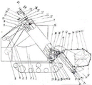
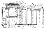
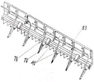
For the purpose of illustrating the invention more clearly, reference will now be made to the accompanying drawings in which: fig. 1 is a side view of the overall structural arrangement of the present invention, fig. 2 is a top view of the transmission of fig. 1, fig. 3 is a cross-sectional view of a longitudinal inclined cleaning and conveying of fig. 1, fig. 4 is a cross-sectional view of fig. 1 for transverse collection and grain and residue separation, fig. 5 is a positioning plate of a reel of fig. 1, fig. 6 is a guide rail view of fig. 2, fig. 7 is a grass conveying clamping view of fig. 1, and fig. 8 is a power transmission view of grass conveying of fig. 1.
To clarify the overall process of the invention, the part names in the figures are denoted separately by reference numerals:
1 a running mechanism 2 a grain storage mechanism 3 a power wheel 4 a grass rolling mechanism 5 a grain feeding barn 6 an arc type leak-proof plate 7 a total power shaft 8 a total power receiving wheel 9 a total transmission belt 10 a grass rolling power output wheel 11 a grass rolling transmission belt 12 a grass rolling transmission wheel 13 a grass rolling driving shaft 14 a grass rolling driven shaft 15 a grass rolling transmission gear 16 a stirring roller 17 a fan impeller 18 a transmission belt 19 with a plurality of rakes a cleaning and conveying bevel gear 21 a cross bridge shaft 22 a fan transmission wheel 23 a cleaning transmission wheel 24 a cleaning transmission belt 25 a cleaning transmission wheel 26 a rake 27 a fan power wheel 28 a fan transmission belt 29 a multipurpose transmission wheel 30 a grain collector 31 a bridge shaft 32 a bridge power wheel 33 a multipurpose transmission wheel 34 a multipurpose transmission belt 35 a grain collector power wheel 36 a multipurpose transmission belt Grain-residue separator power wheel 37, threshing power wheel 38, tension wheel 39, offset bearing seat 40, connecting rod 41, movable knife group 42, grain-residue separator 43, guide rail 44, grain receiving bucket 45, threshing driving roller 46, supporting roller 47, conveying belt 48, speed-changing power transmission belt 49, grain-feeding, straw-shifting and conveying power wheel 50, grain-feeding, straw-shifting and conveying power shaft 51, reel and straw-feeding power wheel 52, cross transmission bevel gear 53, transmission belt 54, reel 55, reel 56, reel 57, straw-feeding supporting wheel 58, reel finger 59, reel 60, vertical crank 61, control handle 62, telescopic U-shaped seat 63, positioning disk 64, tension spring 65, supporting wheel 66, roller 67, straw transmission bevel gear 68, straw transmission chain wheel 70, straw transmission chain 71, tension wheel 72, supporting wheel 73, supporting wheel 74, third supporting wheel 75, fourth supporting wheel 75, supporting wheel 73, second supporting wheel 74, second supporting wheel 73, second supporting wheel 74, third supporting wheel, fourth supporting wheel 75, fourth supporting wheel The supporting wheel 76, the grass pressing elastic strip 77, the operation and control device move the track line 78, the guide strip 79, the discharge opening 80, the transverse screen 81, the positioning pin 83, the clamping plate 84, the grass throwing disk 85 and the grass throwing blade.
In order to describe in detail specific embodiments of the present invention, the structural arrangements are considered with respect to the accompanying drawings; a transmission process; the working principle is detailed in three aspects:
firstly, the structural arrangement is as follows: the whole shown in figure 1 consists of three parts, namely a travelling mechanism 1, a grain storage mechanism 2 and a working mechanism 3-85, the invention only provides the structural position layout of the working mechanism and the grain storage mechanism, and the detailed process of the working mechanism is mainly expressed:
(I), the structural layout of the working mechanism and the grain storage mechanism is as follows: the power machine is fixed on the rear end of the running gear 1, a fuel tank and a grass rolling mechanism 4 are fixed above the power machine, a grain storage mechanism 2 is fixed right above the running gear, the left side, the right side and the front of the grain storage mechanism are vertically in a cabinet shape, a groove with the same width as a grain feeding bin 5 of the working mechanism and the same inclination of the bottom surface is longitudinally arranged in the middle of the upper top, two sides of the groove are closed, the bottom surface is bounded by an arc-shaped leakage-proof plate 6, the lower part is closed, the whole length of the upper part is a feeding hole, and one piece of grain storage mechanism is dug out in front of one side to form the position of an operation table.
(II), a working mechanism: the working principle is divided into a seedling pulling system and a seedling feeding system in sequence; a threshing system; a transverse collection and grain-residue separation system; a longitudinal inclined cleaning and conveying system; a straw cutting, conveying and crushing system. And the power transmission sequence is divided into a constant speed transmission route and a variable speed transmission route: in order to clearly express the relationship among the systems, the association and the layout of each system are gradually expressed from the power transmission starting path to the power transmission ending path according to the inertia of the power transmission route:
the connecting point of the working mechanism and the grain storage mechanism takes the axial lead of the total power shaft 7 as a fulcrum and is transversely arranged on the top surface of the grain storage mechanism, the whole working mechanism can take the fulcrum as the center of a circle and take a plurality of systems in front as the radius, and under the action of external force, the whole systems in front can be lifted up and down, so that the effect of adjusting the height of a straw rod and harvesting can be achieved; the two ends of a total power shaft 7 shown in figure 2 are provided with bearing seats, the bearing seats are fixed on a frame and support the shaft to rotate, the end of the shaft is provided with a total power receiving wheel 8, the total power receiving wheel is sleeved with a total transmission belt 9, the other end of the total transmission belt is sleeved on a power wheel 3 of a power machine, the total power shaft is provided with a grass rolling power output wheel 10, the power output wheel is sleeved with a grass rolling transmission belt 11, the other end of the grass rolling transmission belt is sleeved on a grass rolling power wheel 12, the grass rolling power wheel is fastened on a grass rolling driving shaft 13, the two ends of the grass rolling driving shaft and a grass rolling driven shaft 14 are provided with the bearing seats, the bearing seats are fixed on a shell and support the two shafts to rotate, the middle parts of the two shafts are fastened with a plurality of symmetrical hobbing cutters, the other end of the two shafts is provided with an engaged transmission gear 15, and when the driving shaft rotates, the driven shaft rotates through the engaged gear.
Longitudinal inclined cleaning and grain conveying system: the structure of the system is shown in figure 3, a cross-cut surface is a square shell, a stirring roller 16, a fan impeller 17, a driving belt 18 with a plurality of rakes 26, an arc-shaped screen 19, a semicircular cover, a plurality of guide strips 78, a lifting square support and a lifting square support are arranged on the upper portion of the shell, wherein the upper portion of the shell is shown in figures 1 and 2, the upper portion of the shell is shown in figure 3, the lower portion of the shell is shown in figure 3, the arc-shaped screen 19 is arranged between the stirring roller and the rakes, the upper portions of the stirring roller and the fan impeller are also provided with semicircular covers, the inner surface of the cover above the stirring roller is also obliquely fastened with the plurality of guide strips 78, and the lifting square support is arranged below the two sides of the arc-shaped screen; the lower base of the inclined cleaning mechanism is provided with a plurality of rakes 26 on a transmission belt, the upper half part of the bottom surface is provided with a discharge port 79 communicated with the grain storage bin, and the lower end surface of the discharge port is provided with an arc-shaped leakage-proof plate 6 inserted into the grain storage bin shown in figure 1; the other end of the transmission total power shaft 7 shown in figure 2 is fastened with a cleaning transmission bevel gear 20, the bevel gear is engaged with a transmission bevel gear of a cross axle shaft 21, bearing seats are arranged at both ends of the axle shaft, the bearing seats are fixed on a frame and support the axle shaft to rotate, a fan transmission wheel 22 and a cleaning transmission wheel 23 are arranged at the middle part of the axle, a cleaning transmission belt 24 is sleeved on the cleaning transmission wheel 23, the other end of the transmission belt is sleeved on a cleaning power wheel 25, the cleaning power wheel is fastened at the end of the axle of the stirring roller 16, the bearing seats are arranged at both ends of the axle of the stirring roller, the bearing seats are fixed on a shell and support the stirring roller to rotate, a plurality of rows of stirring rollers are fastened at the middle part of the stirring roller, a plurality of stirring teeth are fastened on each stirring roller, a fan impeller 26 capable of rotating independently is also arranged on the rear shaft of the stirring roller, and a fan power wheel 27 is fastened at the rear end of the fan, the power wheel of the fan is sleeved with a fan transmission belt 28, and the other end of the fan transmission belt is sleeved on the fan transmission wheel 18; the middle part of the main power shaft 7 is also provided with a grain bin for raking grains, transversely collecting grains, separating grain slag, combing grains from straws, mowing and a multipurpose driving wheel 29, the multipurpose driving wheel is sleeved with a multipurpose driving belt 18, the multipurpose driving belt is provided with a plurality of rakes 26, the other end of the multipurpose driving belt provided with the plurality of rakes passes through the upper edge and the lower edge of a grain collector 30 and is sleeved on a power wheel 32 of a transmission bridge shaft 31, the two ends of the transmission bridge shaft are provided with bearing seats, the bearing seats are fixed on a rack and support the transmission bridge shaft to rotate, and when the main power shaft 7 and the multipurpose driving wheel 29 rotate, the transmission bridge shaft 31 and the power wheel 32 can be driven to rotate through the multipurpose driving belt 18 provided with the plurality of rakes.
Power split transmission system: the other end of the transmission bridge shaft 31 is fastened with a multipurpose transmission wheel 33 for transversely collecting grains, separating grain and slag and combing the grains from the straws, a multipurpose transmission belt 34 is sleeved on the multipurpose transmission wheel, the back surface of the multipurpose transmission belt is coated with a grain collector power wheel 35 in a transverse mode shown in figure 1 and then moves upwards, a grain and slag separator power wheel 36 is coated and reversely moves transversely, a threshing power wheel 37 is coated and then moves downwards, a tension wheel 38 is coated and then returns to the multipurpose transmission wheel 33 to form a ring, and when the multipurpose transmission wheel rotates, the grain collector, the grain and slag separator and the thresher can be simultaneously driven to rotate, the rotating direction is the same, and the rotating direction is opposite to that of the multipurpose transmission wheel.
Straw cutting system: the end of the transmission bridge shaft 31 shown in fig. 2 is also fastened with an eccentric bearing seat 39, (not shown in the figure) which is symmetrically extended outwards to form two pin shafts, the two pin shafts are sleeved in two symmetrical lug holes of a connecting rod 40, when the transmission bridge shaft rotates, the eccentric bearing seat swings, two symmetrical pin shafts of the eccentric bearing seat push and pull two symmetrical lugs on the connecting rod to enable the connecting rod to rotate back and forth, the other end of the connecting rod is provided with a bearing seat which is fixed on a frame and supports the connecting rod to rotate back and forth, the end of the connecting rod is fastened with a crank shaft, the other end of the crank shaft is provided with a push-pull rod, the other end of the push-pull rod is connected with a moving knife set 41 for mowing shown in fig. 2, when the connecting rod rotates back and forth, the crank shaft generates a swinging distance and pushes and pulls the moving knife set to move back and forth through the push-pull rod.
Transversely collect cereal grain and cereal sediment piece-rate system: FIG. 4 shows a horizontal U-shaped groove as a housing, a grain and slag separator 42 is arranged above the housing, bearing seats are arranged at two ends of the grain and slag separator shown in FIG. 2, the bearing seats are fixed on plates at two ends of the housing and support the grain and slag separator to rotate, a shaft at one end of the grain and slag separator penetrates out of the bearing seats, a power wheel 36 is fixed on the penetrated shaft head, a multipurpose transmission belt 34 is sleeved on the power wheel, two ends at the middle section of the grain and slag separator are fastened towards the middle and are fastened with helical blades with opposite rotation directions, and the helical blades at the two ends are jointed on straight blades which are fastened axially when rotating to the middle; the lower half of the grain and slag separator shown in FIG. 4 is fitted with an arcuate screen 80; a grain collector 30 is arranged in a U-shaped groove below the screen, bearing blocks are arranged at two ends of the grain collector shown in figure 2, the bearing blocks are fixed on end plates at two ends and support the grain collector to rotate, spiral blades with opposite rotating directions are fastened at the middle section of the grain collector, and when the spiral blades at two sides rotate to the middle, the distance which can be passed by the rakes 26 on the driving belt 18 with a plurality of rakes shown in figure 3 is reserved; the shaft head at one end of the grain collector shown in figure 2 penetrates out of the bearing seat, and a power wheel 35 is fastened at the end of the penetrated shaft and is sleeved with a multipurpose transmission belt 34.
A threshing system: the front edge of a front low and rear high grain receiving hopper 44 shown in figure 1 is circled upwards to form a semicircle, the left side and the right side are fastened on a frame, the rear part is fastened with a U-shaped groove shown in figure 4, a threshing driving roller 45 shown in figure 1 is arranged in the grain receiving hopper, two ends of the driving roller are provided with bearing seats shown in figure 2, the bearing seats are fixed on the frame and support the driving roller to rotate, a shaft head at one end penetrates out of the bearing seats, a power wheel 37 is fastened at the penetrating shaft end, and a multipurpose transmission belt 34 is sleeved on the power wheel; a support roller 46 shown in figure 1 is arranged in the semicircular shell below the grain receiving hopper, bearing blocks shown in figure 2 are arranged at two ends of the support roller, and the bearing blocks are fixed on the frame and can rotate along with the support roller; in FIG. 1, a flexible conveyor belt 47 is sleeved on the driving roller and the supporting roller, and a plurality of rows of comb teeth are fastened on the flexible conveyor belt and are adjacently arranged in a staggered manner; when the driving roller rotates, the conveying belt and the comb teeth can be driven to wrap the supporting roller to rotate, so that the upper surface and the lower surface of the conveying belt and the comb teeth generate parallel motion.
The rotating speeds of the two parts of the grain pulling and feeding system and the grass conveying system can be adjusted to one step only when the rotating speeds of the two parts change along with the speed change of the walking speed, so that the enough threshing time of the ears fed into the grain receiving hopper is ensured. Therefore, the power of the power output mechanism after the speed change in the gearbox is required to be transmitted from the shaft after the speed change in the walking gearbox, and the invention is not described in detail, and the power transmission of the two systems is described by being accompanied by inertia only in the power transmission process after the speed change, and the two systems are described together: the speed-changing power transmission belt 48 shown in fig. 2 is sleeved on a multipurpose power wheel 49 for feeding, shifting and conveying the grass, the power wheel is fastened at the end of a power shaft 50 for feeding, shifting and conveying the grass, bearing seats are arranged at two ends of the power shaft, the bearing seats are fixed on frames at two sides and support the power shaft to rotate, a power wheel 51 for shifting and feeding the grass is fastened in the two bearing seats of the power shaft, the other end of the power shaft also extends out of the bearing seats, and a cross transmission bevel gear 52 is fastened at the end of the extended shaft:
the reel and feed system comprises two reel driving wheels 51, a transmission belt 53 is sleeved on the two reel driving wheels 51, a plurality of reel pressing rollers 54 are symmetrically fastened on the transmission belt 53, the transmission belt 53 shown in figure 1 wraps a plurality of rows of reel shafts 56 on a reel 55 from the upper part, then bypasses a reel feeding supporting wheel 57, and returns to the reel and feed driving wheels 51 to form a ring, the distance between the plurality of reel pressing rollers 54 fastened on the transmission belt is exactly that one reel shaft is arranged behind each reel shaft 56, and one or more reel shafts are arranged between the two reel shafts; the high and low positions of the reel and feeding transmission wheel 51 and the feeding supporting wheel 57 are based on the height of the comb teeth on the flexible conveying belt 47, so that the standing grain roller 54 is ensured not to collide with the moving comb teeth tips when moving upwards; each reel 56 is hung with a plurality of arc-shaped reel fingers 58 with elasticity downwards, two ends of each reel shaft shown in figure 2 are sleeved in supporting seats, each supporting seat at the two ends is symmetrically fixed on a reel disc 59 and can rotate by supporting the reel shaft, one end of each reel shaft extends out of the supporting seat, a vertical crank 60 is fastened at the end of the extending reel shaft, the direction of the vertical crank is opposite to that of the reel fingers, the other end of the vertical crank is fastened with an operating handle 61, the direction of the operating handle is parallel to the reel shaft, an operating handle is sleeved with a U-shaped seat 62 which can stretch and retract and can swing and is shown in figure 5, the inner handle of the U-shaped seat is a flat body, a sliding groove is arranged in the middle of the flat body, a positioning pin 81 is penetrated in the sliding groove and fixed on a limiting disc 63 and controls the U-shaped seat to shift by taking the positioning pin as a reference, the end of the inner handle of the U-shaped seat is hung with a tension spring 64, and the other end of the tension spring is fastened on the inner surface of the U-shaped seat, the tension spring pulls the U-shaped seat and the control handle 61 to the center of the positioning disk through the flat body; the inner wall of the inner ring of the positioning disc is supported by a riding wheel 65 in sections, and an inner shaft of the riding wheel is fixed on the rack to control the positioning disc to rotate; the end of the control handle shown in fig. 2 extends out of the telescopic U-shaped seat, a roller 66 is mounted on the extended control handle, and when the roller rotates downward integrally with the reel and the positioning disk, the roller enters the guide rail groove 43 shown in fig. 6, because the guide rail groove generates downward radial change relative to the positioning disk and the movement track line 77 specified by the control handle, the roller 66 contacts the upper wall of the guide rail and then moves, the control handle and the vertical crank handle are pushed, the support seat on the reel is taken as the center of a circle, the telescopic U-shaped seat on the positioning disk is also driven to swing downward, the guide rail groove transmits the swinging force to the control handle, the reel shaft rotates through the vertical crank handle, and the reel finger tilts backward through the rotary force of reel pulling; when the reel power shaft 50 and the reel driving wheel 51 rotate, the reel and the directional disk are driven to rotate by the driving belt 53, and meanwhile, a plurality of reel pressing rollers are driven to move together.
There is also grass delivery: the cross-drive bevel gear 52 shown in fig. 2 and 8 is engaged with a grass-conveying bevel gear 67 which is fastened to one end of a grass-conveying drive shaft 68 shown in fig. 8 and 1, the grass-conveying drive shaft is provided with a bearing seat which is fixed on the frame and supports the drive shaft to rotate, the other end of the drive shaft is fastened with a grass-conveying drive sprocket 69 shown in fig. 2, the grass-conveying drive sprocket 69 shown in fig. 2 is sleeved with a grass-conveying chain 70 which is sleeved with a tension wheel 71, the grass-conveying chain passes over the front first support wheel 72, passes over the transverse movable cutter group 41, passes over the front second support wheel 73, goes straight to the upper rear, and passes over the rear third grass-throwing and supporting common sprocket 74, the lower part of the common sprocket is provided with a long bearing seat which is shared by a plurality of bearings, the long bearing seat is fixed on the frame and supports the common sprocket to move, and a grass-throwing disk 84 is arranged above the sprocket, a plurality of grass throwing blades 85 are fixedly arranged on the grass throwing disk; the grass conveying chain transversely passes through the rear fourth supporting wheel 75, and then moves forwards and downwards to return to the grass conveying transmission chain wheel 69 to form a ring shape; when the grass conveying transmission collar wheel rotates, the grass conveying chain can be driven to move circularly; the grass conveying chain is arranged on the upper side of the full length of the movable cutter set, a plurality of grass pressing elastic strips 76 shown in figure 7 are pressed, the grass pressing elastic strips are bent forwards and downwards, then are inserted backwards and fastened on the fixed cutter set below the movable cutter set, and the upper ends of the elastic strips are arranged towards the moving direction of the grass conveying chain and are elastically pressed on rolling sleeves between an upper clamping plate 83 and a lower clamping plate 83 of the grass conveying chain; from the second supporting wheel to the third supporting wheel, the outer side of the grass conveying chain is pressed by an elastic pressing strip (not shown in the figure), and the elastic pressing strip passes around the third supporting wheel and then gradually loosens to lose the grass pressing capability.
Secondly, a transmission process:
the power generated by the engine shown in figure 1 is output by the power wheel 3, and drives the total power receiving wheel 8 and the total power shaft 7 shown in figure 2, the grass rolling power output wheel 10, the raking valley, the transverse collecting and threshing and mowing multipurpose driving wheel 29 and the cleaning bevel gear 20 to synchronously rotate through the total driving belt 9 of the working mechanism: the grass-rolling power output wheel 10 drives a grass-rolling driving wheel 12, a grass-rolling driving shaft 13 and a plurality of hobbing cutters fastened on the driving shaft to rotate through a grass-rolling driving belt 11, and a grass-rolling driving gear 15 on the other end of the driving shaft transmits power to a driving gear 15 on a grass-rolling driven shaft, so that the driven shaft and the hobbing cutters fastened on the driven shaft roll oppositely.
The bevel gear 20 at the other end of the total power shaft 7 transmits power to the engaged bevel gears, so that the crossed gap bridge shaft 21, the fan driving wheel 22 fastened on the gap bridge shaft and the cleaning driving wheel 23 rotate simultaneously: wherein, the fan transmission wheel 22 drives the fan power wheel 27 and the fan impeller 17 to rotate through the fan transmission belt 28; the cleaning transmission wheel 23 drives the cleaning power wheel 25 and the stirring roller 16 to rotate through the cleaning transmission belt 24.
Raking the corn, transversely collecting, separating the corn and the dregs, threshing and mowing the multipurpose driving wheel 29, driving the gap bridge power wheel 32, the transmission gap bridge shaft 31, the multipurpose driving wheel 33 and the eccentric bearing seat 39 through the transmission belt 18 with a plurality of rakes, and generating synchronous rotation: the crossing angle between the axis of the eccentric bearing seat 39 and the axis of the transmission bridge shaft 31 makes the eccentric bearing seat swing when the housing does not rotate while rotating, the swinging force pushes and pulls the connecting rod 40 to rotate back and forth, and the crank shaft at the other end of the connecting rod pushes and pulls the moving knife set 41 to move back and forth.
The multipurpose transmission wheel 33 drives four of a grain collection power wheel 35, a grain and residue separation power wheel 36, a threshing power wheel 37 and a tension wheel 38 shown in the figure 1 through the back of the multipurpose transmission belt 34 to rotate in the direction opposite to the multipurpose transmission wheel 33; wherein the power wheel 35 drives the grain collector 30 to rotate; the power wheel 36 drives the grain-slag separator 42 to rotate; the power wheel 37 drives the threshing driving roller 45 to rotate, and then the threshing driving roller 45 drives the flexible conveying belt 47 with comb teeth to move under the tightening action of the supporting roller 46.
(II) variable speed transmission: the power after the speed change of the walking gearbox drives a power shaft 50 for standing grain pulling, feeding and grass conveying, a power wheel 51 for standing grain pulling and feeding and a bevel gear 52 for grass conveying cross transmission, which are fastened on the power shaft, to synchronously rotate by a speed change power transmission belt 48 shown in figure 2: wherein, the power of the reel and feeding power wheel 51 drives the two supporting seats of a plurality of reel shafts 56 shown in figure 1 through the transmission belt 53, so that the reel disc 59 and the reel wheel 55 shown in figure 2 rotate, and simultaneously drives a plurality of reel pressing rollers 54 on the transmission belt shown in figure 1 to move integrally after bypassing the feeding supporting wheel 57; the rotating force of the reel drives the positioning plate 63 to rotate around a plurality of supporting wheels 65 shown in fig. 5 through a plurality of control handles 61 shown in fig. 2, (not shown) because the circle center line of the positioning plate is above the reel axis line, the vertical crank 60 is always kept in a vertical state no matter the reel is rotated to any angle, and because the reel finger 58 shown in fig. 2 is symmetrical to the vertical crank, the reel finger is rotated to any angle and always kept in a drooping state, when each control handle 61 is rotated to the lower part, the roller 66 on the control handle shown in fig. 2 enters the guide rail 43 shown in fig. 6, because the track line of the guide rail is inclined to the movement track line 77 of the control handle, the roller touches the upper wall of the guide rail to force the control handle 61 to move downwards, the control handle at this time strongly pulls the telescopic U-shaped seat, overcomes the pulling force of the tension spring 64 and then extends downwards, and passes through the vertical crank 60 shown in fig. 2 to turn the reel 56, the reel finger 58 is lifted upwards by the rotating force of the reel shaft (not shown), the roller 66 leaves the rear end of the guide rail 47, the pressure is released, the operating handle 61 and the telescopic U-shaped seat 62 are retracted to the original position by the pulling force of the tension spring 64, and the reel finger 58 immediately drops to the original position.
The grass conveying cross transmission bevel gear 52 shown in fig. 2 drives the grass conveying bevel gear 67 shown in fig. 8, the grass conveying transmission shaft 68 and the grass conveying transmission chain wheel 69 to rotate, so that the grass conveying chain 70 sleeved on the grass conveying transmission chain wheel 69 shown in fig. 2 moves under the side pressure wrapping action of the tension wheel 71 and the tightening action of the first supporting wheel 72, the second supporting wheel 73, the third grass throwing and supporting common chain wheel 74 and the fourth supporting wheel 75, wherein the radius of the grass throwing disk 84 and the grass throwing blades 85 above the third grass throwing and supporting common chain wheel is larger than that of the chain wheel 74, and therefore, the linear speed of the rotation of the grass throwing disk and the grass throwing blades is higher than the rotational linear speed of the chain wheel.
Thirdly, the working principle is as follows: to show more in detail that a movement has a plurality of functions and the aim of simplifying the structure to the maximum extent is achieved, the following aspects of the rice pulling and feeding, threshing and conveying, grain and residue separation and transverse collection, longitudinal inclined cleaning and conveying, grass cutting, grass conveying, grass rolling or stacking are expressed in sub-terms:
firstly, under the moving state that the machine body moves forwards, the rotating linear speed of the reel varies along with the fast forward speed of the machine body to be the same as the quality, and the rotating linear speed of the reel is controlled to be faster than the walking speed no matter whether the walking speed is fast or slow; the working principle is as follows: when the seedling pulling finger rotates to the front, the seedling pulling finger is inserted downwards from the top of an upright ear of grain or the waist of a lodging straw and pulled backwards, the seedling pulling finger rotates to the right below and pries backwards to move, after the straw is delivered into the grain receiving hopper in a leakproof way, the seedling pulling finger immediately returns to a drooping original position to continue moving, the stump part of the straw is grown forwards, the straw is in a backwards inclined state, the straw has a force of rebounding forwards at any time, in order to prevent the straw entering the grain receiving hopper from rebounding, a plurality of seedling pressing rollers on a transmission belt are adopted to press the straw in turn, so that the straw cannot be lifted, and the straw is pulled into the grain receiving hopper due to the flow of a plurality of seedling pulling shaft wheels. And the straw coming later presses the advanced straw one by one and feeds the advanced straw to threshing comb teeth.
(II) threshing and conveying: the flexible conveying belt and the threshing comb teeth move downwards along with the threshing driving roller 45 shown in figure 2 at the back upper part, move downwards and obliquely forwards to the front lower part in the grain receiving bucket in a straight line, turn upwards along with the supporting roller 46 shown in figure 1, and are exposed after crossing a semicircular arc at the front edge of the grain receiving bucket, and move upwards and straight, the threshing comb teeth on the upper part move upwards, and when combing the grain rod, the threshing comb teeth on the upper part are staggered due to the narrow distance between the adjacent comb teeth and the position of the front row and the back row of comb teeth, and the linear velocity of the movement is in inertial fit, so that the two and three comb teeth in one row are staggered and alternately collided at the left side and the right side of the grain rod, the grain ears swing at the highest speed, and the grains with grains can not shake very fast along with the grain ears due to the inertia of the weight, and are clamped and threshed by the front row and back rows of comb teeth; the empty shell without rice grains is lighter than the straw, can swing along with the straw at an ultra-fast speed, avoids the combing force of the comb teeth, and is kept on the straw, so that the process of cleaning the empty shell from the grains is not needed, and the beneficial effects of saving power and not damaging the grains are achieved; in addition, in case that grains brought into the grain receiving hopper from the rear upper part slide to the semi-arc-shaped position of the front edge, the grains can be hung by threshing comb teeth, and waste in threshing is avoided; then the linear speed of the reel is faster than the walking speed, and the proportion of the reel changing along with the change of the walking speed is not changed; the grains can not fall into the ground during threshing until the ears of the stalks which are pushed in once all enter the grain receiving hopper, and the grains can be completely threshed only if the time for a plurality of stalk pushing shafts to pass is in the threshing stage; the combed grains fall on the flexible conveyer belt, are conveyed to the top dead center by the movement inertia of the flexible conveyer belt and are thrown into the grain and residue separator.
Violently collecting and separating grain slag: the grains thrown into the grain and residue separator contain broken ears and residual leaves which are rarely damaged by diseases and insect pests, the grains are dropped into the transverse collector through the screen holes by using stirring power generated when the grain and residue separator rotates, the broken ears and the residual leaves are pushed to the middle by the spiral blades on the grain and residue separator, and then the broken ears and the residual leaves are thrown into the longitudinal inclined cleaning cavity by the axial blades; grains falling into the transverse collector are pushed to the middle by the rotation of the spiral rotating blades.
(IV) longitudinally and obliquely cleaning and conveying, wherein a plurality of rows of stirring teeth on the stirring roller 16 shown in the figures 1 and 3 hang the broken ears and the residual leaves to rotate around, centrifugal force is generated during rotation, when the broken ears and the residual leaves rotate to the upper part, the broken ears and the residual leaves touch guide strips 78 obliquely arranged backwards in the cover, the broken ears and the residual leaves move backwards along the guide strips, when the broken ears and the residual leaves rotate to the lower part, the broken ears and the residual leaves touch a screen mesh 19, the hung grains leak out of screen holes, the broken ears and the residual leaves rotate while moving backwards and upwards, when the broken ears and the residual leaves move to a rear upper dead center, the grains on the broken ears are hung and removed, and residues are cut into crushed slag by a slag blower by a cutting edge of a fan impeller 17 rotating at high speed shown in the figures 1 and 2; the fan has a second function, so that negative pressure is generated in the cleaning cavity, dust generated in the threshing process is sucked away, and the environment of an operator is protected; secondly, dust in the grains is sucked away, so that the grains are cleaner; a plurality of rakes 26 on the transmission belt 18 shown in the figures 1 and 3 obliquely downwards from the position close to the arc-shaped screen mesh 19 pass through the upper part of the grain collector shown in the figure 2, bypass the driving wheel and move to a stop point from the lower part of the grain collector to the upper back to circulate in turns, so that grains pushed from the grain collector are directly raked into the grain storage mechanism, and the grains are ensured not to be damaged; the grain feeding device mainly comprises a grain bin device 5, a rake, a grain discharging opening and a grain discharging opening, wherein the grain discharging opening is formed in the lower half of the grain bin device 5; and the height of the working mechanism is adjusted according to the height of the straw, the arc radius of the arc-shaped leakage-proof plate 6 inserted into the granary is equal to the linear distance from the axis of the total power shaft 7 to the arc-shaped plate, so that the bottom surface of the arc-shaped plate always clings to the corresponding position of the granary opening to ensure that grains are not leaked no matter the working mechanism is lifted at will.
(V), mowing, conveying and crushing:
the grass cutting principle is that the grass is cut after threshing, and when the threshing process (II) is connected, a plurality of reel shafts and a plurality of straw pressing roller streams press down the straw which is firstly pulled into the grain receiving hopper layer by layer, and the machine body moves forwards, and compared with the grain receiving hopper, the stump part of the straw which is pulled in by each reel shaft is moved to the lower part from the front and then moved to the rear; then, from the change of the length of the straw entering the grain receiving hopper, the length of the straw entering the grain receiving hopper is changed from the short length to the long length in the period that the root of the straw comes to the lower part of the grain receiving hopper from the front; the length of the grain receiving hopper is shortened from the lower part to the rear part; in the changing process, the included angle between the straw outside the grain receiving hopper and the ground is gradually changed from backward inclination to vertical inclination and then gradually changed from vertical inclination to forward inclination; from threshing process again, the length when the straw begins to get into in the grain receiving fill, must all feed into in the grain receiving fill the ear of grain, just can ensure that the grain of comb-doffing can not fall in the ground and waste, according to the natural law of the grain of comb-doffing toward whereabouts and the motion process of the interior multilayer straw of grain receiving fill again: the upper layer of threshing moves into the grain receiving bucket, the threshed grass is dragged outwards, and then the falling grains are clamped in the grass dragged outwards and are carried out of the grain receiving bucket, so that waste is caused. In order to avoid the waste, the grass is cut off below the front edge of the grain receiving hopper (namely when the grass is just dragged outwards), so that the grass is not dragged outwards. In order to withdraw the grains clamped in the cut grass; but also ensure that the normal threshing is not influenced when the grass is removed; but also reduce the power for moving grass to the maximum; combining these three factors, the walking path of the clamping plate 83 on the grass conveying chain 70 shown in fig. 7 is defined at the front edge of the grain receiving bucket (i.e. when the root of the straw is vertical), the straw is hung when the straw is neither going into the grain receiving bucket nor being dragged outwards, and moves in the direction of the arrow at a linear speed equal to or slightly greater than the walking speed of the machine body to drag the straw into the straw pressing elastic strip 76 to be pressed, so that the cut straw is completely carried on the straw conveying chain, at this time, the stump part of the straw is cut off by the driven knife set 41, after the cut straw moves across the front edge of the grain receiving bucket along with the grass pressing chain, and is pressed by the grass pressing elastic strip at the rear, the wrapped grains are shaken off while being lifted backwards, and the grains move backwards as soon as the third grass throwing and supporting shared collar wheel 74 shown in figure 2, the tail part of the grass which is quickly pulled by the grass throwing blade 85 is turned to the rear part of the grass conveying chain and falls into the grass rolling mechanism to be rolled back to the field or collected for another use.
Claims (8)
1. The invention relates to a multi-purpose threshing-before-cutting half-feeding combine harvester for rice and wheat oil, which comprises: a grain storage mechanism; a longitudinal inclined cleaning and conveying mechanism; a multi-purpose transmission mechanism; a transverse collecting and grain-residue separating mechanism; a threshing mechanism; a reel and feeder mechanism; the straw cutting and conveying mechanism 6.
2. The grain storage mechanism of claim 1 comprising: a square stereo granary has a tank-shaped slot on its top for closing its two sides and lower front part of its bottom, a long grain inlet on its upper back part, a position space for belt passing through the slot and grass rolling mechanism, and an operating table on its front side.
3. A longitudinally inclined cleaning and conveying mechanism according to claim 1 including: the axis line of the total power shaft is taken as a fulcrum, the total power shaft is transversely arranged on the top surface of the grain storage mechanism, the whole body can take the fulcrum as the circle center, a plurality of front systems are taken as the radius, and the front systems can be lifted and lowered under the action of external force, so that the purpose of adjusting the height is achieved; bearing seats are arranged at two ends of a main power shaft, the bearing seats are fixed on a rack and support the shaft to rotate, a main power receiving wheel is arranged at one end of the shaft, a main power transmission belt is sleeved on the main power receiving wheel, the other end of the transmission belt is sleeved on a power wheel of a power machine, a grass rolling power output wheel is arranged on the main power shaft, a grass rolling transmission belt is sleeved on the power output wheel, the other end of the grass rolling transmission belt is sleeved on the grass rolling power wheel, the grass rolling power wheel is fastened on a grass rolling driving shaft, the bearing seats are arranged at two ends of the grass rolling driving shaft and the grass rolling driven shaft, the shaft seats are fixed on a shell and support the two shafts to rotate, a plurality of pairs of symmetrical hobbing cutters are fastened at the middle parts of the two shafts, meshed transmission gears are arranged at the other ends of the two shafts, and the driven shafts can rotate through the meshed transmission gears when the driving shaft rotates; longitudinal inclined cleaning and grain conveying system: the horizontal cutting surface is in a square shell, a stirring roller and a fan impeller are arranged above the horizontal cutting surface, a multi-purpose driving belt with a plurality of rakes is arranged below the horizontal cutting surface, an arc-shaped screen is arranged between the stirring roller and the rakes for separation, semi-circular covers are arranged on the upper half parts of the stirring roller and the fan impeller, a guide strip is fastened on the inner surface of the cover above the stirring roller in an inclined way, and lifting brackets are arranged below two sides of the arc-shaped screen; the lower bottom in the square shell supports a plurality of rakes on a multipurpose transmission belt, the upper half part of the bottom surface is provided with a discharge hole communicated with the interior of the grain storage bin, and the lower side of the discharge hole is provided with an arc-shaped leakage-proof plate inserted into the grain storage bin; the other end of the main power shaft is fastened with a cleaning transmission bevel gear, the bevel gear is engaged with a transmission bevel gear crossed with a gap bridge shaft, bearing seats are arranged at the two ends of the gap bridge shaft, the bearing seats are fixed on a rack and support the gap bridge shaft to rotate, a fan transmission wheel and a cleaning transmission wheel are arranged at the middle part of the gap bridge shaft, a cleaning transmission belt is sleeved on the cleaning transmission wheel, the other end of the transmission belt is sleeved on a cleaning power wheel, the cleaning power wheel is fastened at the shaft end of a stirring roller, the two ends of the shaft of the stirring roller are provided with the bearing seats, the bearing seats are fixed on a shell and support the stirring roller to rotate, a plurality of rows of stirring rods are fastened at the middle part of the stirring roller, a plurality of stirring teeth are fastened on each stirring rod, a fan impeller capable of rotating independently is also mounted on the rear shaft of the stirring roller, the rear end of the fan power wheel is fastened with the fan power wheel, and a fan transmission belt is sleeved on the fan power wheel, the other end of the fan transmission belt is sleeved on the fan transmission wheel; the middle part of the main power shaft is also provided with a grain feeding bin for raking grains, transversely collecting grains, separating grain from slag, combing grains from straws and a multipurpose driving wheel for mowing, the driving wheel is sleeved with a multipurpose driving belt provided with a plurality of rakes, the other end of the multipurpose driving belt passes through the upper edge and the lower edge of the grain collector and is also sleeved on a power wheel of a transmission gap bridge shaft, the two ends of the transmission gap bridge shaft are provided with bearing seats, the bearing seats are fixed on a rack and support the transmission gap bridge shaft to rotate, and when the main power shaft and the multipurpose driving wheel rotate, the transmission gap bridge shaft and the power wheel can be driven to rotate through the multipurpose driving belt provided with the plurality of rakes.
4. The utility drive mechanism of claim 1, comprising: the other end of the transmission bridge shaft is fastened with a multipurpose transmission wheel for transversely collecting grains, separating grain and slag and combing the grains from the straws, a multipurpose transmission belt is sleeved on the multipurpose transmission wheel, the back surface of the multipurpose transmission belt goes upwards after transversely wrapping a power wheel of a grain collector, goes reversely and transversely after wrapping a power wheel of a grain and slag separator, goes downwards after wrapping a threshing power wheel, returns to the multipurpose transmission wheel to form a ring after wrapping a tension wheel, and when the multipurpose transmission wheel rotates, the power wheels of the grain collector, the grain and slag separator and the thresher can be simultaneously driven to rotate, and the rotation directions are the same, and only the rotation directions of the multipurpose transmission wheel are opposite; straw cutting system: the end of the transmission bridge shaft is also fastened with an eccentric bearing seat, two pin shafts symmetrically extend outwards from the eccentric bearing seat, two symmetrical lug hanging rods of a connecting rod are sleeved on the two pin shafts, when the transmission bridge shaft rotates, the eccentric bearing seat swings back and forth, the two pin shafts symmetrical to the eccentric bearing seat push and pull the two lug hanging rods symmetrical to the connecting rod, so that the connecting rod can rotate back and forth, the bearing seat is arranged at the other end of the connecting rod and fixed on the frame to support the back and forth rotation of the connecting rod, the other end of the connecting rod is fastened with a crank shaft, the other end of the crank shaft is provided with a push-pull rod, the other end of the push-pull rod is connected with a moving cutter set for mowing, when the connecting rod rotates back and forth, the crank shaft generates a swinging distance, and the push-pull rod pushes and pulls the power set to generate back and forth movement.
5. The lateral collection grain and grain residue separation mechanism of claim 1 comprising: a horizontal U-shaped groove shell, a grain-slag separator is arranged above the horizontal U-shaped groove shell, bearing seats are arranged at two ends of the grain-slag separator, the bearing seats are fixed on plates at two ends of the shell and support the grain-slag separator to rotate, a shaft at one end of the grain-slag separator penetrates out of the bearing seats, a power wheel is fixedly arranged on the penetrated shaft head, a multipurpose transmission belt is sleeved on the power wheel, two ends of the middle section of the grain-slag separator are fixedly provided with spiral blades with opposite rotation directions towards the middle, and the spiral blades at two ends are jointed on a straight blade which is axially fastened when rotating to the middle; the lower half part of the grain-slag separator is provided with an arc-shaped screen; a transverse collector is arranged in a U-shaped groove below the screen, bearing blocks are arranged at two ends of the transverse collector, the bearing blocks are fixed on end plates at the two ends and support the transverse collector to rotate, spiral blades with opposite rotating directions are fastened towards the middle at two ends of the middle section of the transverse collector, and when the spiral blades at two sides rotate to the middle, a space distance is reserved so that a plurality of rakes on the multipurpose transmission belt can pass through; the shaft head at one end of the transverse collector penetrates out of the bearing seat, a power wheel is fastened at the end of the penetrated shaft, and a multipurpose transmission belt is sleeved on the power wheel.
6. The threshing mechanism of claim 1, comprising: the grain receiving hopper is connected with a U-shaped groove of a bottom shell of the transverse collector into a whole, the bottom surface of the grain receiving hopper is obliquely arranged towards the front lower part, the front edge of the grain receiving hopper is upwards circled into a semicircular shape, and the left side and the right side of the grain receiving hopper are fastened on the rack; a threshing driving roller is arranged in the shell at the rear upper part of the grain receiving hopper, bearing seats are arranged at two ends of the driving roller, the bearing seats are fixed on the frame and support the driving roller to rotate, one end of the shaft penetrates out of the bearing seats to fasten a power wheel, and a multipurpose driving belt is sleeved on the power wheel; a support roller is arranged in the semicircular shell at the front lower part of the grain receiving hopper, bearing seats are arranged at two ends of the support roller, the bearing seats are fixed on the frame, and the support roller can rotate; the driving roller and the supporting roller are sleeved with flexible conveying belts, a plurality of rows of comb teeth are fastened on the flexible conveying belts, and the comb teeth of each row are adjacently arranged in a staggered manner; when the driving roller rotates, the conveying belt and the comb teeth can be driven to wrap the supporting roller to rotate, so that the upper surface and the lower surface of the conveying belt and the comb teeth generate parallel motion.
7. The reel and feeder mechanism of claim 1 comprising: the speed-changing power transmission belt is sleeved on a multipurpose power wheel for feeding, poking and conveying the grass, the power wheel is fastened at the end of a power shaft for feeding, poking and conveying the grass, bearing seats are arranged at two ends of the power shaft, the bearing seats are fixed on frames at two sides and support the power shaft to rotate, the power shaft is fastened at the middle section of the power shaft and is provided with the power wheel for poking and feeding the grass, a transmission belt is sleeved on two poking and feeding transmission wheels, a plurality of grass pressing rollers are symmetrically fastened on the transmission belt, the transmission belt wraps a plurality of rows of poking shafts on the poking wheels from the upper part, then returns to a poking and feeding shared transmission wheel for forming a ring, the space between the plurality of grass pressing rollers fastened on the transmission belt is exactly one behind each poking shaft, and one or more grass pressing rollers are arranged between the two poking shafts; the high and low positions of the reel and feeding transmission wheel and the feeding supporting wheel are based on the height of comb teeth on the flexible conveying belt, and the pressure standing grain roller is ensured not to collide with the moving comb tip when moving upwards; a plurality of arc-shaped and elastic seedling pulling fingers are hung downwards on each seedling pulling shaft; two ends of each reel are sleeved in the supporting seats, each supporting seat at the two ends is symmetrically fixed on the reel and supports the reel to rotate, one end of each reel extends out of the supporting seat, a vertical crank handle is fastened at the end of the extended reel shaft, the direction of the vertical crank handle is opposite to the direction of the reel finger, an operating handle is fastened at the other end of the vertical crank handle, the orientation of the operating handle is parallel to the reel shaft, a U-shaped seat which can stretch and retract and can swing is sleeved on the operating handle, the inner handle of the U-shaped seat is a flat body, a sliding groove is formed in the middle of the flat body, a positioning pin penetrates through the sliding groove and is fixed on the limiting disc, the telescopic U-shaped seat is controlled to be capable of moving by taking the positioning pin as a reference, a tension spring is hung at the end head of the inner handle of the telescopic U-shaped seat, the other end of the tension spring is fastened on the outer wall of the inner ring of the limiting disc, and the tension spring pulls the telescopic U-shaped seat and the control handle to the center of the positioning disc through the flat body; the inner wall of the inner ring of the positioning disc is supported by riding wheels in sections, and an inner shaft of the riding wheel is fixed on the rack to control the positioning disc to rotate; the end of the control handle penetrates out of the telescopic U-shaped seat, a roller is arranged at the extending position, when the roller rotates to the lower part integrally along with the reel and the positioning disc, the roller enters the guide rail groove, because the guide rail groove generates radial downward movement change for the movement track line specified by the control handle relative to the positioning disc, the roller touches the upper wall of the guide rail and moves backwards, the control handle, the telescopic U-shaped seat and the vertical turning handle are pushed, the supporting seat on the reel is taken as the center of a circle and swings downwards together, the guide rail groove transmits the swinging force to the control handle, the reel shaft rotates through the vertical turning handle, the reel finger is lifted backwards through the rotating force of the reel drawer, after moving for a distance, the roller leaves the guide rail and loses pressure, and under the pulling force of the tension spring, the telescopic U-shaped seat, the control handle and the reel fat immediately return to the original position; when the reel and feeding power shaft and the driving wheel rotate, the reel and the directional disk are driven to rotate by the driving belt, and simultaneously, the plurality of reel pressing rollers are driven to move together.
8. The grass delivery mechanism of claim 1 comprising: a grass conveying bevel gear is engaged on a crossed transmission bevel gear at the other end of the power shaft for reeling, feeding and conveying grass, the grass conveying bevel gear is fastened on a grass conveying transmission shaft, a bearing seat is arranged in the grass conveying transmission shaft, the bearing seat is fixed on a rack and supports the transmission shaft to rotate, the other end of the transmission shaft is fastened with a grass conveying transmission chain wheel, a grass conveying chain is sleeved on the grass conveying transmission chain wheel, a tensioning wheel is sleeved on the grass conveying chain wheel, the grass conveying chain passes through a transverse moving cutter group after passing through a first support wheel in front and passes through a second support wheel in front, the grass conveying chain goes straight to the upper rear and bypasses a third grass throwing and supporting common chain wheel, a long shaft below the common chain wheel is provided with a plurality of bearings and a long bearing seat shared by the bearings, the long bearing seat is fixed on the rack and supports the common chain wheel to rotate, a grass throwing disk is arranged above the common chain wheel, a plurality of grass throwing blades are fixedly arranged on the grass throwing disc; the grass conveying chain transversely passes through the rear fourth supporting wheel and then moves forwards and downwards to return to the grass conveying transmission chain wheel to form a ring, and when the grass conveying transmission chain wheel rotates, the grass conveying chain can be driven to move in a ring shape; the grass conveying chain passes through the upper edge of the full length of the movable cutter set, a plurality of grass pressing elastic strips are pressed, the initial ends of the grass pressing elastic strips are fastened on the fixed cutter set below the driven cutter set, extend forwards for a section and then extend obliquely towards the rear upper side, and are elastically pressed on rolling sleeves between the upper clamping plate and the lower clamping plate of the grass conveying chain after being bent; the elastic pressing strip is pressed on the outer side of the grass conveying chain in the backward direction, and the elastic pressing strip gradually loosens when reaching the third supporting wheel, so that the grass pressing capability is lost.
Priority Applications (1)
| Application Number | Priority Date | Filing Date | Title |
|---|---|---|---|
| CN202110085330.5A CN114793601A (en) | 2021-01-22 | 2021-01-22 | Rice and wheat oil multipurpose half-feeding combine harvester capable of threshing before cutting |
Applications Claiming Priority (1)
| Application Number | Priority Date | Filing Date | Title |
|---|---|---|---|
| CN202110085330.5A CN114793601A (en) | 2021-01-22 | 2021-01-22 | Rice and wheat oil multipurpose half-feeding combine harvester capable of threshing before cutting |
Publications (1)
| Publication Number | Publication Date |
|---|---|
| CN114793601A true CN114793601A (en) | 2022-07-29 |
Family
ID=82525257
Family Applications (1)
| Application Number | Title | Priority Date | Filing Date |
|---|---|---|---|
| CN202110085330.5A Pending CN114793601A (en) | 2021-01-22 | 2021-01-22 | Rice and wheat oil multipurpose half-feeding combine harvester capable of threshing before cutting |
Country Status (1)
| Country | Link |
|---|---|
| CN (1) | CN114793601A (en) |
-
2021
- 2021-01-22 CN CN202110085330.5A patent/CN114793601A/en active Pending
Similar Documents
| Publication | Publication Date | Title |
|---|---|---|
| US10905048B2 (en) | Self-adjustable feeder for sugar cane harvesting device | |
| CN106561150B (en) | Non-line sensitive grain threshing header | |
| JPS62500213A (en) | Crop harvesting machine and crop harvesting method | |
| CN104350883B (en) | Sugar-cane cutting machine | |
| WO2020168793A1 (en) | Plant harvesting and processing apparatus for direct-harvesting of corn kernel having high water content | |
| CN209949878U (en) | High-water-content corn grain direct harvesting plant harvesting and processing equipment | |
| CN201674797U (en) | Multi-functional small-sized grain combined harvester | |
| CN205161144U (en) | Harvester with chain vibration isolation sieves device | |
| CN105052358B (en) | A kind of ginger stalk, which is crushed, collects briquetting device | |
| CN210868798U (en) | Sunflower harvesting header | |
| CN204090557U (en) | Cane harvester | |
| CN108811785B (en) | Corn harvesting and threshing device for agricultural machinery | |
| CN109769466A (en) | Centre of gravity 4 wheel driven maize harvesting machine | |
| CN217470767U (en) | A dual system harvester for banded compound planting of maize soybean | |
| CN110637606A (en) | Corn harvester capable of harvesting fresh corn | |
| CN116784089A (en) | Regenerated japonica rice harvester | |
| CN114793601A (en) | Rice and wheat oil multipurpose half-feeding combine harvester capable of threshing before cutting | |
| CN214628172U (en) | Crawler-type corn harvester | |
| CN112106519B (en) | Castor harvesting platform for castor harvesting machine | |
| CN213214389U (en) | Castor picking machine's picking platform structure | |
| CN211152825U (en) | Small-size full-feeding peanut picker | |
| CN211982667U (en) | Self-propelled harvester | |
| CN212629229U (en) | Sunflower seed harvester convenient to ejection of compact | |
| CN211152792U (en) | Rice harvesting device | |
| CN114600634A (en) | Harvesting and threshing integrated corn harvester |
Legal Events
| Date | Code | Title | Description |
|---|---|---|---|
| PB01 | Publication | ||
| PB01 | Publication |