CN114770875B - High-precision medical instrument part rapid forming die - Google Patents
High-precision medical instrument part rapid forming die Download PDFInfo
- Publication number
- CN114770875B CN114770875B CN202210714420.0A CN202210714420A CN114770875B CN 114770875 B CN114770875 B CN 114770875B CN 202210714420 A CN202210714420 A CN 202210714420A CN 114770875 B CN114770875 B CN 114770875B
- Authority
- CN
- China
- Prior art keywords
- fixed
- die
- movable
- mold
- mould
- Prior art date
- Legal status (The legal status is an assumption and is not a legal conclusion. Google has not performed a legal analysis and makes no representation as to the accuracy of the status listed.)
- Active
Links
Images


Classifications
-
- B—PERFORMING OPERATIONS; TRANSPORTING
- B29—WORKING OF PLASTICS; WORKING OF SUBSTANCES IN A PLASTIC STATE IN GENERAL
- B29C—SHAPING OR JOINING OF PLASTICS; SHAPING OF MATERIAL IN A PLASTIC STATE, NOT OTHERWISE PROVIDED FOR; AFTER-TREATMENT OF THE SHAPED PRODUCTS, e.g. REPAIRING
- B29C45/00—Injection moulding, i.e. forcing the required volume of moulding material through a nozzle into a closed mould; Apparatus therefor
- B29C45/17—Component parts, details or accessories; Auxiliary operations
- B29C45/38—Cutting-off equipment for sprues or ingates
-
- B—PERFORMING OPERATIONS; TRANSPORTING
- B29—WORKING OF PLASTICS; WORKING OF SUBSTANCES IN A PLASTIC STATE IN GENERAL
- B29C—SHAPING OR JOINING OF PLASTICS; SHAPING OF MATERIAL IN A PLASTIC STATE, NOT OTHERWISE PROVIDED FOR; AFTER-TREATMENT OF THE SHAPED PRODUCTS, e.g. REPAIRING
- B29C45/00—Injection moulding, i.e. forcing the required volume of moulding material through a nozzle into a closed mould; Apparatus therefor
- B29C45/17—Component parts, details or accessories; Auxiliary operations
- B29C45/40—Removing or ejecting moulded articles
- B29C45/4005—Ejector constructions; Ejector operating mechanisms
Abstract
The invention discloses a high-precision medical instrument part rapid forming die, and particularly relates to the related technical field of dies. The high-precision medical instrument part rapid forming die can automatically eject, take down and collect injection-molded parts, effectively reduces labor cost investment, and is provided with a demolding and water outlet removing system, a movable die side cutting piece is matched with a fixed die side cutting piece to complete water outlet material shearing, and water outlet materials can automatically fall off and be removed during die opening, so that the working efficiency of the whole die is improved.
Description
Technical Field
The invention relates to the technical field of forming dies, in particular to a high-precision rapid forming die for medical instrument parts.
Background
In short, the mold is a tool for manufacturing a molded article, the tool is composed of various parts, different molds are composed of different parts, the processing of the shape of the article is realized mainly through the change of the physical state of the molded material, and when a vehicle lamp is processed, the molded article needs to be put into the mold for injection molding.
The medical apparatus refers to instruments, equipment, appliances, in-vitro diagnostic reagents and calibrators, materials and other similar or related articles which are directly or indirectly used for human bodies, and comprises required computer software, precision molds are often required in the production process of medical apparatus parts, and most of the existing injection molds have the following defects:
1. after the injection molding is finished, the molded part is usually taken out manually, and the automatic ejection and demolding of the part cannot be realized;
2. when the part is moulded plastics, can form the mouth of a river material in runner or the mouth of moulding plastics outside the shaping chamber of product, mostly reprocess the fashioned part and get rid of mouth of a river material and polish after the completion of moulding plastics among the prior art, its work efficiency remains to be promoted.
Disclosure of Invention
The invention mainly aims to provide a high-precision medical instrument part rapid forming die which can effectively solve the problems that automatic ejection and demolding of parts cannot be realized, the formed parts are reprocessed after injection molding is finished, a water gap material is removed, grinding and polishing are carried out, and the working efficiency is reduced in the prior art.
In order to achieve the purpose, the invention adopts the technical scheme that:
the utility model provides a high-accuracy medical instrument part rapid prototyping mould, includes die carrier, fixed mould and movable mould, its characterized in that: the fixed die is fixed on one side of the upper end of the die carrier, and the movable die is arranged on the other side of the die carrier and can slide relative to the die carrier to realize die closing and die opening;
one side of the top of the die carrier, which is close to the fixed die, is provided with an ejection mechanism for automatically ejecting the injection-molded part in a matching way with the fixed die, and the other side of the top of the die carrier is provided with a demolding and water draining port system for pushing the movable die to realize die assembly and die opening of the fixed die and the movable die;
the drawing of patterns and the mouth system of anhydrating are including the drawing of patterns pneumatic cylinder that is fixed in the die carrier top, locate the output of drawing of patterns pneumatic cylinder and carry out driven bolster, the roof of locating the bolster top, locate the movable mould side cutting piece in the movable mould and locate the fixed mould in and use the cover half side cutting piece that cuts off the mouthful waste material of moulding plastics with the cooperation of movable mould side cutting piece, the one end that the pneumatic cylinder of drawing of patterns was kept away from to the bolster is used for promoting the movable mould to slide in order to realize the compound die on the die carrier with movable mould fixed connection.
Preferably, a fixed mold side boss is arranged in the middle of one end, close to the movable mold, of the fixed mold, a fixed mold side injection cavity is arranged in the middle of the fixed mold side boss, a fixed mold side injection port is formed in the top of the fixed mold side injection cavity, two groups of fixed mold side mold cores are symmetrically arranged in the fixed mold side injection cavity, fixed mold side slideways for allowing the fixed mold side mold cores to enter or exit are further arranged on two sides of one end, close to the movable mold, of the fixed mold, fixed grooves are formed in two sides of one end, close to the movable mold, of the fixed mold, sliding seats are arranged in the fixed grooves, material taking hydraulic cylinders are arranged at one ends, close to the movable mold, of the two sliding seats, and the two fixed mold side mold cores are driven by the two material taking hydraulic cylinders respectively;
the fixed die side injection molding cavity is positioned in a rectangular cavity formed among the four baffles.
Preferably, the sliding seat includes the fixed block, the four corners of fixed block all is equipped with rather than integrated into one piece's spacing strip, the four corners of fixed slot all is equipped with the spacing groove of using with spacing strip cooperation.
Preferably, the ejection mechanism comprises an ejection hydraulic cylinder fixed at the top of the die carrier, the output end of the ejection hydraulic cylinder is provided with a push plate parallel to the fixed die, two connecting rods are symmetrically arranged at one end of the push plate far away from the ejection hydraulic cylinder, the two connecting rods respectively penetrate through the two fixed grooves and are fixed with the sliding seat, and the connecting rods are connected with the fixed die in a sliding manner.
Preferably, a movable die side boss is arranged in the middle of one end, close to the fixed die, of the movable die, clamping plates are arranged on two sides of the movable die side boss, the two clamping plates are tightly attached to two sides of the fixed die side boss respectively in a die closing state, and two sliding blocks are symmetrically arranged at the bottom of the movable die;
the movable mould side boss is close to the one end middle part of fixed mould and is equipped with the movable mould side mouth of moulding plastics that uses with the cooperation of cover half side injection moulding mouth, the movable mould side injection moulding chamber that uses with the cooperation of cover half side injection moulding chamber and the movable mould side slide that uses with the cooperation of cover half side slide and the mounting groove that uses with the baffle cooperation.
Preferably, a movable die side chute is arranged in the middle of the movable die, a middle stop block is arranged on the side wall of the movable die side chute, an extension plate is arranged at one end, away from the buffer piece, of the top plate, the movable die side cutting piece is slidably mounted in the movable die side chute, two limit blocks are symmetrically arranged on one side, close to the extension plate, of the movable die side cutting piece, two side stop blocks are symmetrically arranged at an outlet, close to one side of the fixed die, of the movable die side chute, buffer springs are arranged in front of the side stop blocks and the limit blocks, and a movable die side half hole is formed in the middle of one side, close to the fixed die, of the movable die side cutting piece;
the middle part of fixed mould is equipped with cover half side spout, cover half side cutting piece slidable mounting is in cover half side spout, the lateral wall of cover half side spout is equipped with the bellying that sideslips the groove syntropy with the cover half, the guiding groove that uses with the bellying cooperation is seted up at the one end middle part that the movable mould was kept away from to cover half side cutting piece, the one end that cover half side cutting piece is close to the movable mould is equipped with cover half side hole, the one end both sides that the movable mould was kept away from to cover half side cutting piece are equipped with the stop part, and the stop part sideslips and be equipped with a plurality of coil spring between a lateral wall of keeping away from the movable mould in groove with the cover half.
Preferably, the fixed die side sliding groove, the movable die side sliding groove and the top plate are all located at the same horizontal height and aligned with each other.
Preferably, the bolster includes fixed cover, the top of fixed cover is located to the roof, be equipped with pars contractilis and multiunit carbide spring in the fixed cover, and pars contractilis and carbide spring link to each other, the one end that the pars contractilis close to the movable mould is equipped with connecting portion, the one end that connecting portion are close to the movable mould is equipped with the connection pad.
Preferably, the die carrier includes the chassis, the top both sides of chassis all are equipped with the fixing base, two fixing base tops are located respectively to ejection mechanism and drawing of patterns and water gap system, two be equipped with two sets of slide rails jointly between the fixing base, the fixed mould passes through the bolt fastening in two slide rail top one sides, movable mould slidable mounting is in two slide rail top opposite sides.
Preferably, an inclined blanking plate used for guiding the molded injection molding piece is arranged between the two sliding rails, and a collecting box used for collecting the injection molding piece is further arranged at the position, below the two sliding rails, on the bottom frame.
Compared with the prior art, the invention has the following beneficial effects:
1. according to the invention, the two material taking hydraulic cylinders are started, the two fixed die side sliding channels are controlled to return through the material taking hydraulic cylinders, the fixed die side mold cores can return by utilizing the fixed die side sliding channels, the injection molded parts can be kept still between the four baffle plates under the blocking of the four baffle plates, and the injection molded parts can automatically fall down along with the complete separation of the two fixed die side mold cores from the four baffle plates, so that the process of automatically taking out the injection molded parts is completed, and the investment of labor cost can be effectively reduced.
2. By arranging the demoulding and water gap removing system, the fixed mould side cutting piece can be pushed by using the movable mould side cutting piece after the injection moulding is finished and before an injection moulding piece is completely cooled and formed, at the moment, the injection molding small hole formed by the fixed mould side half hole and the movable mould side half hole is separated from the injection molding channel formed by the fixed mould side injection port and the movable mould side injection port, the connection between the injection molding channel formed by the fixed mould side injection port and the movable mould side injection port and the fixed mould side injection cavity and the movable mould side injection cavity is cut off, the water gap material is cut, and the water gap material can automatically fall off when the mould is opened, so that the working efficiency of the whole mould is improved.
Drawings
FIG. 1 is a schematic diagram of an overall structure of an embodiment of the present invention;
FIG. 2 is a side view of a stent of the present invention;
fig. 3 is a schematic view of the overall structure of the ejection mechanism of the present invention;
FIG. 4 is a schematic view showing a fixed mold of the present invention in an ejected and released state;
FIG. 5 is a schematic view of the overall structure of the movable mold of the present invention;
FIG. 6 is a schematic view showing a state where the fixed mold and the movable mold of the present invention are closed;
FIG. 7 is a schematic view showing the overall structure of the scaffold of the present invention;
FIG. 8 is a schematic overall structure diagram of a second embodiment of the present invention;
FIG. 9 is a schematic view of the overall structure of the stripping and dewatering system of the present invention;
FIG. 10 is an enlarged view of the structure of FIG. 9 at A in accordance with the present invention;
FIG. 11 is a cutaway schematic view of the movable die of the present invention;
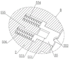
FIG. 12 is an enlarged view of the structure of FIG. 11 at B in accordance with the present invention;
fig. 13 is a cross-sectional view of the cushioning member of the present invention.
In the figure: 1. a mold frame; 11. a chassis; 12. a fixed seat; 13. a slide rail; 14. inclining the blanking plate; 15. a collection box; 2. a fixed mold; 21. a fixed die side boss; 22. a fixed-mold side injection molding port; 23. a fixed die side injection molding cavity; 24. a sliding seat; 241. a fixed block; 242. a limiting strip; 25. fixing a mold side mold core; 26. a baffle plate; 27. a fixed-mold side slideway; 28. fixing grooves; 29. a material taking hydraulic cylinder; 3. moving the mold; 31. a side boss of the movable mould; 32. moving mould side injection molding mouth; 33. a movable mould side injection mould cavity; 34. a splint; 35. a slider; 36. mounting grooves; 37. a movable mould side slideway; 4. an ejection mechanism; 41. ejecting a hydraulic cylinder; 42. pushing the plate; 43. a connecting rod; 5. demolding and dewatering the water port system; 51. a demoulding hydraulic cylinder; 52. a buffer member; 521. fixing a sleeve; 522. a connecting portion; 523. a connecting disc; 524. a telescopic part; 525. a hard spring; 53. a top plate; 54. cutting the sheet on the side of the movable mold; 541. a side stop block; 542. a middle block; 543. an extension plate; 544. a limiting block; 545. a buffer spring; 546. a movable mould side chute; 547. a half hole at the side of the movable mold; 55. cutting the slice at the fixed die side; 551. a guide groove; 552. a fixed die side half hole; 553. a blocking portion; 554. a fixed mold side chute; 555. a boss portion; 556. a coil spring.
Detailed Description
In order to make the technical means, the creation characteristics, the achievement purposes and the effects of the invention easy to understand, the invention is further described with the specific embodiments.
Example one
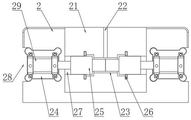
As shown in fig. 1-8, the embodiment discloses a high-precision medical instrument part rapid prototyping mold, which comprises a mold frame 1, and a fixed mold 2 and a movable mold 3 respectively arranged on the mold frame 1, wherein the fixed mold 2 is fixed on one side of the upper end of the mold frame 1, and the movable mold 3 is arranged on the other side of the mold frame 1 and is controlled by a hydraulic system to slide relative to the mold frame 1 so as to realize mold closing and mold opening with the fixed mold 2.
Specifically, referring to fig. 2-4, a fixed mold side boss 21 is arranged in the middle of one end of the fixed mold 2 close to the movable mold 3, a fixed mold side injection cavity 23 is arranged in the middle of the fixed mold side boss 21, a fixed mold side injection opening 22 is arranged at the top of the fixed mold side injection cavity 23, two groups of fixed mold side mold cores 25 are symmetrically arranged inside the fixed mold side injection cavity 23, the two fixed mold side mold cores 25 are always positioned in the fixed mold side injection cavity 23 in the injection molding process, a gap formed between the two fixed mold side mold cores 25 and the side wall of the fixed mold side injection cavity 23 is used as a molding cavity to mold the injection molding material, two fixed mold ends of the fixed mold 2 close to the movable mold 3 are both provided with fixing grooves 28, the fixing grooves 28 are both provided with sliding seats 24, one ends of the two sliding seats 24 close to the movable mold 3 are both provided with material taking hydraulic cylinders 29, and the two fixed mold side mold cores 25 are respectively driven by the two material taking hydraulic cylinders 29;
specifically, in order to quickly take out a part after the part is molded, in this embodiment, an ejection mechanism 4 is disposed on one side of the top of the mold frame 1 close to the fixed mold 2, specifically, as shown in fig. 3, the ejection mechanism 4 includes an ejection hydraulic cylinder 41 fixed on the top of the mold frame 1, a push plate 42 parallel to the fixed mold 2 is disposed at an output end of the ejection hydraulic cylinder 41, two connecting rods 43 are symmetrically disposed at one end of the push plate 42 away from the ejection hydraulic cylinder 41, the two connecting rods 43 respectively penetrate through the two fixing grooves 28 and are fixed to the sliding seat 24, and the connecting rods 43 are connected to the fixed mold 2 in a sliding manner;
therefore, when the injection molding is finished and the injection molding part needs to be taken out after cooling molding, the push plate 42 can be used for pushing the two connecting rods 43 by only starting the ejection hydraulic cylinder 41, so that the sliding seats 24 slide in the fixed grooves 28, the material taking hydraulic cylinder 29 is ejected by the two sliding seats 24, the two fixed mold side mold cores 25 are driven to be simultaneously moved out of the fixed mold side injection cavity 23, and the injection molded part can be moved out together.
In order to guarantee the stability of sliding seat 24 when removing in fixed slot 28, this embodiment has carried out special shape design to sliding seat 24, specifically, please refer to fig. 4, sliding seat 24 includes fixed block 241, the four corners of fixed block 241 all is equipped with rather than integrated into one piece's spacing strip 242, the four corners of fixed slot 28 all is equipped with the spacing groove of using with spacing strip 242 cooperation, consequently, can utilize the spacing cooperation that spacing strip 242 and fixed slot 28 four corners were seted up, guarantee the stability of the removal of fixed slot 28, improve the reliability.
Further, in order to enable the parts finished by injection molding to be automatically taken down and reduce the labor input cost, four baffles 26 are further arranged in the middle of one end, close to the movable mold 3, of the fixed mold side boss 21 in the embodiment, the fixed mold side injection cavity 23 is located in a rectangular cavity formed among the four baffles 26, fixed mold side runners 27 for allowing the fixed mold side mold cores 25 to enter or exit are further arranged on two sides of one end, close to the movable mold 3, of the fixed mold side boss 21, and the two fixed mold side mold cores 25 can slide left and right in the two fixed mold side runners 27 respectively.
The specific implementation mode is as follows: after the two material taking hydraulic cylinders 29 are pushed by the ejection hydraulic cylinders 41 to be ejected, the injection-molded part is located between the four baffles 26, the two material taking hydraulic cylinders 29 are started, the two fixed mold side slideways 27 are controlled to return through the material taking hydraulic cylinders 29, the fixed mold side mold cores 25 can return through the fixed mold side slideways 27, the injection-molded part can be kept still between the four baffles 26 under the blocking of the four baffles 26, the injection-molded part can automatically fall along with the complete separation of the two fixed mold side mold cores 25 from the four baffles 26, the injection-molded part is automatically taken out, and the injection-molded part can be taken out next time after being recovered to the original state.
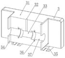
In the above embodiment, the movable mold 3 is controlled by a hydraulic system to slide on the mold frame 1 to cooperate with the fixed mold 2 to realize mold closing and mold opening, specifically, as shown in fig. 5, a movable mold side boss 31 is provided in the middle of one end of the movable mold 3 close to the fixed mold 2, clamping plates 34 are provided on both sides of the movable mold side boss 31, and in a mold closing state, the two clamping plates 34 are respectively tightly attached to both sides of the fixed mold side boss 21 to ensure that the fixed mold 2 is tightly attached to the movable mold 3;
in addition, the middle part of one end of the movable mould side lug boss 31 close to the fixed mould 2 is provided with a movable mould side injection opening 32 matched with the fixed mould side injection opening 22 for use, a movable mould side injection cavity 33 matched with the fixed mould side injection cavity 23 for use, a movable mould side slide way 37 matched with the fixed mould side slide way 27 for use and a mounting groove 36 matched with the baffle 26 for use;
specifically, the fixed mold side injection port 22 is matched with the movable mold side injection port 32, both the fixed mold side injection port 22 and the movable mold side injection port 32 are arranged in a semi-cylindrical shape, and are combined to form a complete injection channel, so that when the mold is practical, raw materials can be injected by using the injection channel;
the movable mold side injection molding cavity 33 is matched with the fixed mold side injection molding cavity 23 to form a finished part molding cavity; the fixed mould side slide way 27 is matched with the movable mould side slide way 37 to form a complete channel for enabling the fixed mould side mould core 25 to enter or exit;
the four mounting grooves 36 are arranged and correspond to the four baffle plates 26 one by one, and the four baffle plates 26 are respectively inserted into the four mounting grooves 36 in a mold closing state so as to avoid influence on a mold closing.
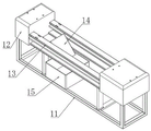
Further, as shown in fig. 7, the mold frame 1 in this embodiment includes an underframe 11, the underframe 11 is used to effectively support the entire mold, both sides of the top of the underframe 11 are provided with fixing seats 12, the ejection mechanism 4 and the hydraulic system for pushing the movable mold 3 to move are respectively provided at the tops of two fixing seats 12, and two sets of slide rails 13 are provided between the two fixing seats 12;
specifically, the fixed mold 2 is fixed on one side of the tops of the two slide rails 13 through bolts, the two slide blocks 35 are symmetrically arranged at the bottom of the movable mold 3, and the movable mold 3 is slidably mounted on the other side of the tops of the two slide rails 13 through the two slide blocks 35.
In order to guide and collect the injection molding parts which are demolded and fall off automatically, an inclined blanking plate 14 for guiding the molding injection molding parts is arranged between the two sliding rails 13 in the embodiment, a collecting box 15 for collecting the injection molding parts is further arranged at the position below the two sliding rails 13 on the bottom frame 11, the collecting box 15 is arranged right below an outlet of the inclined blanking plate 14, the molded parts fall down and then fall above the inclined blanking plate 14, and the parts can be collected uniformly by entering the collecting box 15 through the inclined blanking plate 14.
Meanwhile, in order to avoid the injection-molded parts from being damaged irreversibly by strong impact, the surface of the inclined blanking plate 14 may be provided with a cushion for buffering, including but not limited to a sponge cushion and a rubber cushion.
Example two
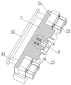
In this embodiment, a hydraulic system for driving the movable mold 3 to move is further improved on the basis of the first embodiment, as shown in fig. 8 to 13, the hydraulic system for controlling the movable mold 3 to move is replaced by a demolding and water removing system 5 in this embodiment, so as to directly remove the water gap material of the injection molding part during the injection molding process, thereby reducing the subsequent processing steps.
Specifically, as shown in fig. 9, the mold releasing and water draining system 5 includes a mold releasing hydraulic cylinder 51 fixed to the top of the mold frame 1, a buffer member 52 provided at an output end of the mold releasing hydraulic cylinder 51 and driven by the mold releasing hydraulic cylinder 51, a top plate 53 provided at the top of the buffer member 52, a movable mold side cutting piece 54 provided in the movable mold 3, and a fixed mold side cutting piece 55 provided in the fixed mold 2 and used in cooperation with the movable mold side cutting piece 54 to cut off the waste material of the injection mold, wherein one end of the buffer member 52 away from the mold releasing hydraulic cylinder 51 is fixedly connected to the movable mold 3 for pushing the movable mold 3 to slide on the mold frame 1 to achieve mold closing.
The mounting method of the movable die side cutting piece 54:
specifically, referring to fig. 9-10, a moving mold side chute 546 is disposed in the middle of the moving mold 3, a middle stopper 542 is disposed on a side wall of the moving mold side chute 546, an extension plate 543 is disposed at an end of the top plate 53 away from the buffer 52, the moving mold side cutting piece 54 is slidably mounted in the moving mold side chute 546, two stoppers 544 are symmetrically disposed on a side of the moving mold side cutting piece 54 close to the extension plate 543, two side stoppers 541 are symmetrically disposed at an outlet of the moving mold side chute 546 close to the fixed mold 2, a buffer spring 545 is disposed between the side stoppers 541 and the stoppers 544, and a moving mold side half-hole 547 is disposed in the middle of a side of the moving mold side cutting piece 54 close to the fixed mold 2;
therefore, the movable mold side cutting piece 54 can be pushed out from the movable mold side slide groove 546 by the extension plate 543, the movable mold side cutting piece 54 is prevented from completely falling off from the movable mold side slide groove 546 by the side stoppers 541, and the movable mold side cutting piece 54 can be returned to the initial position by the buffer spring 545 engaged with the middle stopper 542 after the extension plate 543 is retracted, and the movable mold side half hole 547 is completely overlapped with the movable mold side injection molding orifice 32 when the movable mold side cutting piece 54 is at the initial position, so that smooth injection molding can be performed.
Mounting manner of the fixed mold side cutting piece 55:
specifically, referring to fig. 11 to 12, a fixed mold side chute 554 is disposed in the middle of the fixed mold 2, the fixed mold side cutting blade 55 is slidably mounted in the fixed mold side chute 554, a protrusion 555 in the same direction as the fixed mold side chute 554 is disposed on a side wall of the fixed mold side chute 554, a guide groove 551 used in cooperation with the protrusion 555 is disposed in the middle of one end of the fixed mold side cutting blade 55 away from the movable mold 3, a fixed mold side half hole 552 is disposed at one end of the fixed mold side cutting blade 55 close to the movable mold 3, a blocking portion 553 is disposed on two sides of one end of the fixed mold side cutting blade 55 away from the movable mold 3, and a plurality of coil springs 556 are disposed between the blocking portion 553 and one side wall of the fixed mold side chute 554 away from the movable mold 3.
It can be seen that, in the initial state, the fixed mold side half hole 552 and the fixed mold side injection port 22 completely coincide so as to facilitate injection molding, and meanwhile, the fixed mold side cutting piece 55 can enter the fixed mold side sliding groove 554 under the action of the movable mold side cutting piece 54, and is limited and guided by the cooperation of the bulge 555 and the guiding groove 551, at this time, the injection molding small hole formed by the fixed mold side half hole 552 and the movable mold side half hole 547 breaks away from the injection molding channel formed by the fixed mold side injection port 22 and the movable mold side injection port 32, and the cutting removal of the nozzle material is completed.
In order to ensure that the movable mold side cut piece 54 can be smoothly used in cooperation with the fixed mold side cut piece 55, the fixed mold side slide groove 554, the movable mold side slide groove 546 and the top plate 53 are all located at the same level and aligned with each other, so that the movable mold side cut piece 54 can smoothly enter the fixed mold side slide groove 554.
Further, as shown in fig. 13, the buffer 52 includes a fixing sleeve 521, the top plate 53 is disposed on the top of the fixing sleeve 521, a telescopic portion 524 and a plurality of sets of hard springs 525 are disposed in the fixing sleeve 521, the telescopic portion 524 is connected to the hard springs 525, a connecting portion 522 is disposed at one end of the telescopic portion 524 close to the movable mold 3, and a connecting plate 523 is disposed at one end of the connecting portion 522 close to the movable mold 3, wherein the stiffness coefficient of the hard springs 525 can be selected according to the requirement of actual use, which is a conventional design;
therefore, the present embodiment has three working phases, which are specifically as follows:
the first stage is a mold closing stage:
after the demoulding hydraulic cylinder 51 is started, the movable mould 3 can be pushed to approach the fixed mould 2 through the buffer part 52, so that the mould closing of the fixed mould 2 and the movable mould 3 is realized, and the hard spring 525, the telescopic part 524 and the fixed sleeve 521 are matched, so that a certain buffer effect can be started by using the hard spring 525 in the mould closing process, and the reliability of the whole mould is improved;
after the first stage is finished, injection molding can be carried out, and after the injection molding is finished and before the mold is cooled and formed, the second stage is carried out;
the second stage is a water draining material stage:
in a mold closing state, the demolding hydraulic cylinder 51 is started to continuously push one side of the buffer 52 box to move close to the fixed mold 2, at the moment, the top plate 53 pushes the extension plate 543 to enter the movable mold side sliding groove 546, the movable mold side cutting piece 54 is continuously pushed, the movable mold side cutting piece 54 can push the fixed mold side cutting piece 55, at the moment, an injection molding small hole formed by the fixed mold side half hole 552 and the movable mold side half hole 547 is separated from an injection molding channel formed by the fixed mold side injection port 22 and the movable mold side injection port 32, and the connection between the injection molding channel formed by the mold side injection port 22 and the movable mold side injection port 32 and the fixed mold side injection cavity 23 and the movable mold side injection cavity 33 is cut out, so that the cutting of the injection molding nozzle material is completed;
the third stage is a rollback stage:
after the second stage is completed, the injection molding piece is cooled and molded, then the demolding hydraulic cylinder 51 is started to enable the buffering member 52 to retreat, in the retreating process, the fixed mold side cutting piece 55 returns to the initial position under the action of the coil spring 556, the movable mold side cutting piece 54 also returns to the initial position under the coordination of the buffer spring 545, along with the continuous retreating of the buffering member 52, the fixed mold 2 and the movable mold 3 are separated to complete mold opening, and at the moment, the water gap material in the injection molding small hole formed by the fixed mold side half hole 552 and the movable mold side half hole 547 and the water gap material in the injection molding channel formed by the fixed mold side injection port 22 and the movable mold side injection port 32 naturally fall.
It should be noted that the specific installation manners, circuit arrangement connection manners and control manners of the hydraulic system for controlling the movable mold 3 to move in the first embodiment and the material taking hydraulic cylinder 29, the ejecting hydraulic cylinder 41 and the demolding hydraulic cylinder 51 in the second embodiment are conventional designs in the prior art, and are not described in detail in the present invention.
Meanwhile, cooling channels can be designed in the fixed die 2 and the movable die 3 in the invention, and the dies can be rapidly cooled by adopting circulating water flow so as to further improve the working efficiency, which is also a conventional design in the field and is not repeated here.
The foregoing shows and describes the general principles and features of the present invention, together with the advantages thereof. It will be understood by those skilled in the art that the present invention is not limited to the embodiments described above, which are given by way of illustration of the principles of the present invention, but that various changes and modifications may be made without departing from the spirit and scope of the invention, and such changes and modifications are within the scope of the invention as claimed. The scope of the invention is defined by the appended claims and equivalents thereof.
Claims (6)
1. The utility model provides a high-accuracy medical instrument part rapid prototyping mould, includes die carrier (1), fixed mould (2) and movable mould (3), its characterized in that: the fixed die (2) is fixed on one side of the upper end of the die carrier (1), and the movable die (3) is arranged on the other side of the die carrier (1) and can slide relative to the die carrier (1) to realize die assembly and die opening;
one side, close to the fixed mold (2), of the top of the mold base (1) is provided with an ejection mechanism (4) which is used for being matched with the fixed mold (2) to realize automatic ejection of the injection molded part, and the other side of the top of the mold base (1) is provided with a demolding and water draining port system (5) which is used for pushing the movable mold (3) to realize mold closing and mold opening of the fixed mold (2) and the movable mold (3);
the demolding and water removing port system (5) comprises a demolding hydraulic cylinder (51) fixed to the top of the mold frame (1), a buffer piece (52) arranged at the output end of the demolding hydraulic cylinder (51) and driven by the demolding hydraulic cylinder (51), a top plate (53) arranged at the top of the buffer piece (52), a movable mold side cutting piece (54) arranged in the movable mold (3) and a fixed mold side cutting piece (55) arranged in the fixed mold (2) and matched with the movable mold side cutting piece (54) to cut off waste materials of an injection molding port, wherein one end, far away from the demolding hydraulic cylinder (51), of the buffer piece (52) is fixedly connected with the movable mold (3) and is used for pushing the movable mold (3) to slide on the mold frame (1) to realize mold closing; the fixed die is characterized in that a fixed die side boss (21) is arranged in the middle of one end, close to the movable die (3), of the fixed die (2), a fixed die side injection cavity (23) is arranged in the middle of the fixed die side boss (21), a fixed die side injection opening (22) is formed in the top of the fixed die side injection cavity (23), two groups of fixed die side die cores (25) are symmetrically arranged in the fixed die side injection cavity (23), fixed die side bosses (21) are further arranged on two sides, close to the movable die (3), of one end, close to the fixed die (25), of each fixed die side injection cavity (27) and are used for allowing the fixed die side die cores (25) to enter or exit, fixed side sliding channels (27) are further arranged on two sides, close to the movable die (3), of the fixed die (2) are both sides, close to the movable die (3), of each fixed die side die cores (28) are provided with a sliding seat (24), one ends, close to the movable die (3), of the two sliding seats (24) are provided with material taking hydraulic cylinders (29), and the fixed die side die cores (25) are respectively driven by two material taking hydraulic cylinders (29);
the middle part of one end, close to the movable mould (3), of the fixed mould side boss (21) is also provided with four baffle plates (26), and the fixed mould side injection cavity (23) is positioned in a rectangular cavity formed among the four baffle plates (26);
a movable mould side boss (31) is arranged in the middle of one end, close to the fixed mould (2), of the movable mould (3), clamping plates (34) are arranged on two sides of the movable mould side boss (31), in addition, the two clamping plates (34) are tightly attached to two sides of the fixed mould side boss (21) respectively in a mould closing state, and two sliding blocks (35) are symmetrically arranged at the bottom of the movable mould (3);
a movable mould side injection molding opening (32) matched with the fixed mould side injection molding opening (22) for use, a movable mould side injection molding cavity (33) matched with the fixed mould side injection molding cavity (23) for use, a movable mould side slide way (37) matched with the fixed mould side slide way (27) for use and a mounting groove (36) matched with the baffle (26) for use are arranged in the middle of one end, close to the fixed mould (2), of the movable mould side boss (31);
a movable die side sliding groove (546) is arranged in the middle of the movable die (3), a middle stop block (542) is arranged on the side wall of the movable die side sliding groove (546), an extending plate (543) is arranged at one end, away from the buffer piece (52), of the top plate (53), the movable die side cutting piece (54) is installed in the movable die side sliding groove (546) in a sliding mode, two limit blocks (544) are symmetrically arranged on one side, close to the extending plate (543), of the movable die side cutting piece (54), two side stop blocks (541) are symmetrically arranged at one side outlet, close to the fixed die (2), of the movable die side sliding groove (546), a buffer spring (545) is arranged in front of each side stop block (541) and each limit block (544), and a movable die side half hole (547) is arranged in the middle of one side, close to the fixed die (2), of the movable die side cutting piece (54);
a fixed die side sliding groove (554) is formed in the middle of the fixed die (2), the fixed die side cutting piece (55) is slidably mounted in the fixed die side sliding groove (554), a protruding part (555) which is in the same direction as the fixed die side sliding groove (554) is formed in the side wall of the fixed die side sliding groove (554), a guide groove (551) which is matched with the protruding part (555) for use is formed in the middle of one end, away from the movable die (3), of the fixed die side cutting piece (55), a fixed die side half hole (552) is formed in one end, close to the movable die (3), of the fixed die side cutting piece (55), a blocking part (553) is formed in two sides of one end, away from the movable die (3), of the fixed die side cutting piece (55), and a plurality of spiral springs (556) are arranged between the blocking part (553) and one side wall, away from the movable die (3), of the fixed die side sliding groove (554);
the fixed mold side sliding groove (554), the movable mold side sliding groove (546) and the top plate (53) are all located at the same horizontal height and are aligned with each other.
2. The high-precision medical instrument part rapid forming die as claimed in claim 1, wherein: sliding seat (24) include fixed block (241), the four corners of fixed block (241) all is equipped with rather than integrated into one piece's spacing strip (242), the four corners of fixed slot (28) all is equipped with the spacing groove of using with spacing strip (242) cooperation.
3. The high-precision medical instrument part rapid forming die as claimed in claim 1, wherein: the ejection mechanism (4) comprises an ejection hydraulic cylinder (41) fixed at the top of the die carrier (1), the output end of the ejection hydraulic cylinder (41) is provided with a push plate (42) parallel to the fixed die (2), one end of the push plate (42) far away from the ejection hydraulic cylinder (41) is symmetrically provided with two connecting rods (43), the two connecting rods (43) penetrate through the two fixing grooves (28) respectively and are fixed with the sliding seat (24), and the connecting rods (43) are connected with the fixed die (2) in a sliding manner.
4. The high-precision medical instrument part rapid forming die as claimed in claim 1, wherein: bolster (52) are including fixed cover (521), the top of fixed cover (521) is located in roof (53), be equipped with pars contractilis (524) and multiunit carbide spring (525) in fixed cover (521), and pars contractilis (524) link to each other with carbide spring (525), the one end that pars contractilis (524) are close to movable mould (3) is equipped with connecting portion (522), the one end that connecting portion (522) are close to movable mould (3) is equipped with connection pad (523).
5. The high-precision medical instrument part rapid forming die as claimed in claim 1, wherein: die carrier (1) includes chassis (11), the top both sides of chassis (11) all are equipped with fixing base (12), two fixing base (12) tops are located respectively, two to ejection mechanism (4) and drawing of patterns and water gap system (5) be equipped with two sets of slide rails (13) between fixing base (12) jointly, fixed mould (2) are fixed in two slide rails (13) top one side through the bolt, movable mould (3) slidable mounting is in two slide rails (13) top opposite sides.
6. The high-precision medical instrument part rapid forming die as claimed in claim 5, wherein: an inclined blanking plate (14) used for guiding the molded injection molding part is arranged between the two sliding rails (13), and a collecting box (15) used for collecting the injection molding part is further arranged at the position, below the two sliding rails (13), on the bottom frame (11).
Priority Applications (1)
| Application Number | Priority Date | Filing Date | Title |
|---|---|---|---|
| CN202210714420.0A CN114770875B (en) | 2022-06-23 | 2022-06-23 | High-precision medical instrument part rapid forming die |
Applications Claiming Priority (1)
| Application Number | Priority Date | Filing Date | Title |
|---|---|---|---|
| CN202210714420.0A CN114770875B (en) | 2022-06-23 | 2022-06-23 | High-precision medical instrument part rapid forming die |
Publications (2)
| Publication Number | Publication Date |
|---|---|
| CN114770875A CN114770875A (en) | 2022-07-22 |
| CN114770875B true CN114770875B (en) | 2022-11-08 |
Family
ID=82422318
Family Applications (1)
| Application Number | Title | Priority Date | Filing Date |
|---|---|---|---|
| CN202210714420.0A Active CN114770875B (en) | 2022-06-23 | 2022-06-23 | High-precision medical instrument part rapid forming die |
Country Status (1)
| Country | Link |
|---|---|
| CN (1) | CN114770875B (en) |
Families Citing this family (1)
| Publication number | Priority date | Publication date | Assignee | Title |
|---|---|---|---|---|
| CN116749458B (en) * | 2023-08-16 | 2023-12-19 | 南通瑞卓模塑有限公司 | Injection mold for plastic housing processing convenient to drawing of patterns |
Citations (10)
| Publication number | Priority date | Publication date | Assignee | Title |
|---|---|---|---|---|
| CN201346824Y (en) * | 2009-01-14 | 2009-11-18 | 圣美精密工业(昆山)有限公司 | Injection mold |
| CN207522985U (en) * | 2017-09-22 | 2018-06-22 | 台州市黄岩方胜模塑有限公司 | Mould emptier is taken out in bellows part mold with camber |
| CN208789005U (en) * | 2018-09-17 | 2019-04-26 | 上海千煜精密模具工程有限公司 | A kind of mold trims pouring gate structure automatically |
| CN111361111A (en) * | 2020-03-29 | 2020-07-03 | 金鑫 | Injection mold |
| CN211467322U (en) * | 2019-11-29 | 2020-09-11 | 金裕泰(惠州)实业有限公司 | Socket shell injection mold with uniform glue injection |
| CN212097365U (en) * | 2020-04-14 | 2020-12-08 | 中山市兴达汽车配件有限公司 | Automobile injection mold with water gap automatically falling off |
| CN213675198U (en) * | 2020-09-14 | 2021-07-13 | 烟台精锐模具有限公司 | Automatic cut mouth of a river plastic goods injection mold |
| CN213704381U (en) * | 2020-08-25 | 2021-07-16 | 武汉市明秀工程技术有限责任公司 | Be used for many jiao kou of ppr pipe fitting mould to cut mouth of a river equipment automatically |
| CN214188243U (en) * | 2021-01-14 | 2021-09-14 | 东莞市誉嘉塑料模具有限公司 | Spraying mould internal cutting injection mold is exempted from to 5G cell-phone shell |
| CN216658776U (en) * | 2021-11-02 | 2022-06-03 | 合肥伟德工业科技有限公司 | Injection molding stub bar precision cutting device |
-
2022
- 2022-06-23 CN CN202210714420.0A patent/CN114770875B/en active Active
Patent Citations (10)
| Publication number | Priority date | Publication date | Assignee | Title |
|---|---|---|---|---|
| CN201346824Y (en) * | 2009-01-14 | 2009-11-18 | 圣美精密工业(昆山)有限公司 | Injection mold |
| CN207522985U (en) * | 2017-09-22 | 2018-06-22 | 台州市黄岩方胜模塑有限公司 | Mould emptier is taken out in bellows part mold with camber |
| CN208789005U (en) * | 2018-09-17 | 2019-04-26 | 上海千煜精密模具工程有限公司 | A kind of mold trims pouring gate structure automatically |
| CN211467322U (en) * | 2019-11-29 | 2020-09-11 | 金裕泰(惠州)实业有限公司 | Socket shell injection mold with uniform glue injection |
| CN111361111A (en) * | 2020-03-29 | 2020-07-03 | 金鑫 | Injection mold |
| CN212097365U (en) * | 2020-04-14 | 2020-12-08 | 中山市兴达汽车配件有限公司 | Automobile injection mold with water gap automatically falling off |
| CN213704381U (en) * | 2020-08-25 | 2021-07-16 | 武汉市明秀工程技术有限责任公司 | Be used for many jiao kou of ppr pipe fitting mould to cut mouth of a river equipment automatically |
| CN213675198U (en) * | 2020-09-14 | 2021-07-13 | 烟台精锐模具有限公司 | Automatic cut mouth of a river plastic goods injection mold |
| CN214188243U (en) * | 2021-01-14 | 2021-09-14 | 东莞市誉嘉塑料模具有限公司 | Spraying mould internal cutting injection mold is exempted from to 5G cell-phone shell |
| CN216658776U (en) * | 2021-11-02 | 2022-06-03 | 合肥伟德工业科技有限公司 | Injection molding stub bar precision cutting device |
Also Published As
| Publication number | Publication date |
|---|---|
| CN114770875A (en) | 2022-07-22 |
Similar Documents
| Publication | Publication Date | Title |
|---|---|---|
| CN114770875B (en) | High-precision medical instrument part rapid forming die | |
| CN217454802U (en) | Large-scale automobile auxiliary instrument board die with large sliding block synchronous external core pulling mechanism | |
| CN111231233A (en) | Three-plate mold | |
| CN211566824U (en) | Injection mold convenient for discharging | |
| CN217021248U (en) | Injection mold with automatic cutout mechanism | |
| CN210733077U (en) | Injection mold for machining of X-ray imaging equipment parts | |
| CN115042393A (en) | Mechanism for automatically separating injection molding sprue from product and injection molding method | |
| CN212421980U (en) | Injection mold and injection system | |
| CN110154330B (en) | Core-pulling ejection mechanism of injection mold | |
| CN110682509B (en) | Forming die for washing machine roller product | |
| CN207120428U (en) | A kind of reverse buckle demolding mechanism | |
| CN211968190U (en) | Die carrier device convenient to location | |
| CN220362937U (en) | Large slide block core pulling mechanism for left and right side plates of electric vehicle | |
| CN216267368U (en) | Automatic mould of drawing of patterns | |
| CN213947305U (en) | Electric vehicle left and right side cover sliding block inclined top combined type demoulding mechanism | |
| CN212860247U (en) | Injection mold | |
| CN218505146U (en) | Cold runner mold with cooling nozzle | |
| CN219256359U (en) | Injection molding drawing of patterns frock structure | |
| CN220219510U (en) | Electric tricycle front headlight face guard mould with interior drawing of patterns mechanism | |
| CN218876166U (en) | Injection mold of dust collector floor brush cover body | |
| CN218798925U (en) | Casting mould slider demoulding structure | |
| CN218111585U (en) | Forming die of buckle seal | |
| CN217993347U (en) | Injection mold for automobile decoration strip | |
| CN219405219U (en) | Reinforced commercial vehicle gear lever shield die | |
| CN220362900U (en) | Injection mold capable of automatically removing water gap |
Legal Events
| Date | Code | Title | Description |
|---|---|---|---|
| PB01 | Publication | ||
| PB01 | Publication | ||
| SE01 | Entry into force of request for substantive examination | ||
| SE01 | Entry into force of request for substantive examination | ||
| GR01 | Patent grant | ||
| GR01 | Patent grant |