CN114753350A - Assembled pile cap for composite foundation - Google Patents
Assembled pile cap for composite foundation Download PDFInfo
- Publication number
- CN114753350A CN114753350A CN202210377252.0A CN202210377252A CN114753350A CN 114753350 A CN114753350 A CN 114753350A CN 202210377252 A CN202210377252 A CN 202210377252A CN 114753350 A CN114753350 A CN 114753350A
- Authority
- CN
- China
- Prior art keywords
- sleeve
- main board
- stirrup
- tenon
- plate
- Prior art date
- Legal status (The legal status is an assumption and is not a legal conclusion. Google has not performed a legal analysis and makes no representation as to the accuracy of the status listed.)
- Withdrawn
Links
- 239000002131 composite material Substances 0.000 title claims abstract description 14
- 230000002787 reinforcement Effects 0.000 claims abstract description 76
- 229910000831 Steel Inorganic materials 0.000 claims abstract description 65
- 239000010959 steel Substances 0.000 claims abstract description 65
- 238000003466 welding Methods 0.000 claims abstract description 15
- 230000003014 reinforcing effect Effects 0.000 claims description 28
- 238000004519 manufacturing process Methods 0.000 claims description 8
- 239000004570 mortar (masonry) Substances 0.000 claims description 7
- 239000010687 lubricating oil Substances 0.000 claims description 6
- 239000011248 coating agent Substances 0.000 claims description 3
- 238000000576 coating method Methods 0.000 claims description 3
- 238000005520 cutting process Methods 0.000 claims description 3
- 239000007787 solid Substances 0.000 claims description 3
- 238000009415 formwork Methods 0.000 claims description 2
- 239000012634 fragment Substances 0.000 claims description 2
- 229910001294 Reinforcing steel Inorganic materials 0.000 claims 1
- 230000009286 beneficial effect Effects 0.000 abstract description 2
- 238000009435 building construction Methods 0.000 abstract description 2
- 210000003205 muscle Anatomy 0.000 description 20
- 238000010276 construction Methods 0.000 description 3
- 239000002689 soil Substances 0.000 description 2
- 241001391944 Commicarpus scandens Species 0.000 description 1
- 238000010009 beating Methods 0.000 description 1
- 230000007547 defect Effects 0.000 description 1
- 238000010586 diagram Methods 0.000 description 1
- 230000000694 effects Effects 0.000 description 1
- 238000011065 in-situ storage Methods 0.000 description 1
- 238000003780 insertion Methods 0.000 description 1
- 230000037431 insertion Effects 0.000 description 1
- 238000009434 installation Methods 0.000 description 1
- 238000012423 maintenance Methods 0.000 description 1
- 238000000034 method Methods 0.000 description 1
- 230000000149 penetrating effect Effects 0.000 description 1
- 230000003068 static effect Effects 0.000 description 1
- 239000004575 stone Substances 0.000 description 1
Images


Classifications
-
- E—FIXED CONSTRUCTIONS
- E02—HYDRAULIC ENGINEERING; FOUNDATIONS; SOIL SHIFTING
- E02D—FOUNDATIONS; EXCAVATIONS; EMBANKMENTS; UNDERGROUND OR UNDERWATER STRUCTURES
- E02D5/00—Bulkheads, piles, or other structural elements specially adapted to foundation engineering
- E02D5/22—Piles
- E02D5/223—Details of top sections of foundation piles
-
- B—PERFORMING OPERATIONS; TRANSPORTING
- B28—WORKING CEMENT, CLAY, OR STONE
- B28B—SHAPING CLAY OR OTHER CERAMIC COMPOSITIONS; SHAPING SLAG; SHAPING MIXTURES CONTAINING CEMENTITIOUS MATERIAL, e.g. PLASTER
- B28B23/00—Arrangements specially adapted for the production of shaped articles with elements wholly or partly embedded in the moulding material; Production of reinforced objects
- B28B23/02—Arrangements specially adapted for the production of shaped articles with elements wholly or partly embedded in the moulding material; Production of reinforced objects wherein the elements are reinforcing members
-
- B—PERFORMING OPERATIONS; TRANSPORTING
- B28—WORKING CEMENT, CLAY, OR STONE
- B28B—SHAPING CLAY OR OTHER CERAMIC COMPOSITIONS; SHAPING SLAG; SHAPING MIXTURES CONTAINING CEMENTITIOUS MATERIAL, e.g. PLASTER
- B28B7/00—Moulds; Cores; Mandrels
- B28B7/0002—Auxiliary parts or elements of the mould
-
- B—PERFORMING OPERATIONS; TRANSPORTING
- B28—WORKING CEMENT, CLAY, OR STONE
- B28B—SHAPING CLAY OR OTHER CERAMIC COMPOSITIONS; SHAPING SLAG; SHAPING MIXTURES CONTAINING CEMENTITIOUS MATERIAL, e.g. PLASTER
- B28B7/00—Moulds; Cores; Mandrels
- B28B7/16—Moulds for making shaped articles with cavities or holes open to the surface, e.g. with blind holes
-
- E—FIXED CONSTRUCTIONS
- E02—HYDRAULIC ENGINEERING; FOUNDATIONS; SOIL SHIFTING
- E02D—FOUNDATIONS; EXCAVATIONS; EMBANKMENTS; UNDERGROUND OR UNDERWATER STRUCTURES
- E02D3/00—Improving or preserving soil or rock, e.g. preserving permafrost soil
- E02D3/02—Improving by compacting
- E02D3/08—Improving by compacting by inserting stones or lost bodies, e.g. compaction piles
-
- E—FIXED CONSTRUCTIONS
- E02—HYDRAULIC ENGINEERING; FOUNDATIONS; SOIL SHIFTING
- E02D—FOUNDATIONS; EXCAVATIONS; EMBANKMENTS; UNDERGROUND OR UNDERWATER STRUCTURES
- E02D5/00—Bulkheads, piles, or other structural elements specially adapted to foundation engineering
- E02D5/22—Piles
- E02D5/24—Prefabricated piles
- E02D5/30—Prefabricated piles made of concrete or reinforced concrete or made of steel and concrete
Abstract
An assembly pile cap for a composite foundation belongs to the technical field of building construction, and comprises a top plate and a fixing kit thereof, wherein the top plate is provided with a ring strip-shaped groove, the fixing kit comprises a main plate, a ring strip-shaped tenon on the upper surface of the main plate and a fixing sleeve on the lower surface of the main plate, a steel bar keel of the fixing kit comprises a main plate steel reinforcement cage, a ring-shaped tenon steel reinforcement cage on the upper side of the main plate steel reinforcement cage and a sleeve steel reinforcement cage on the lower side of the main plate steel reinforcement cage, the ring-shaped tenon steel reinforcement cage is formed by welding tenon stirrups on the vertexes of triangular tenon supports, and the sleeve steel reinforcement cage is formed by welding lower sleeve stirrups on the vertexes of right-angled triangle supports; the top plate has the beneficial effects that only the annular strip-shaped groove is arranged on the top plate, so that the strength of the top plate is effectively ensured; the triangular tenon support frame and the right-angled triangle support frame can increase the strength of the keel and form a mutually coordinated stable support structure with the main board reinforcement cage, so that the fixed sleeve is stably connected with the tubular pile, the annular strip-shaped tenon is stably connected with the top plate, and the overall quality of the pile cap is improved.
Description
Technical Field
The invention relates to the technical field of building construction, in particular to an assembled pile cap for a composite foundation.
Background
Concrete pipe pile is an effective form of soft foundation treatment, and the pipe pile is inserted and beaten into the soil body and reaches the bearing layer through the form of pile driver vibration or static pressure, and pile cap is poured at the pile top after the insertion and beating is completed, and keel and broken stone are laid to form a composite foundation, so that the effect of reducing foundation settlement for soft soil foundation reinforcement is achieved, and the requirement of later-stage construction is met. The existing precast pile is produced by adopting a building industrialization method, has the advantages of high production efficiency, stable quality, relatively low cost and the like, and can obviously shorten the construction period. The pile cap of present precast pile has cast-in-place and prefabricated two kinds of modes, but cast in situ causes can work efficiency low, the quality is difficult to guarantee, maintenance time is long scheduling problem for the advantage of precast pile can not obtain abundant performance. The prefabricated pile cap has the problems of heavy self weight, difficulty in transportation and installation, unreasonable connection with the prefabricated pile and the like.
For this purpose, patent document CN105586967B discloses a prefabricated pile cap for composite foundation, which includes a top plate and a fixing sleeve connected to the lower side surface of the top plate; a plurality of locking rods are vertically distributed in the fixing external member, each locking rod extends out of the upper end face of the fixing external member, and the lower end part of the fixing external member is provided with a blind hole for sleeving a precast pile; the top plate is correspondingly provided with a locking through hole for the locking rod to pass through, the top plate is fixedly connected with the fixing sleeve through a locking nut, and the locking nut is screwed on the locking rod penetrating through the upper side face of the top plate. The scheme decomposes the pile cap into the top plate and the fixed external member, so that the construction speed and quality of the project can be effectively improved, and the manufacturing cost is reduced.
The scheme has two major defects, namely, the top plate is provided with a square groove (1-2), the corresponding surface of the top plate is provided with a retaining groove (1-3), and the top plate is also provided with a locking through hole (1-1), so that the thickness of the position on the top plate is obviously reduced, the strength of the position is weakened, the top plate is easy to damage or even break during carrying, and the top plate is also easy to break during application; and the sleeve changing part of the fixed sleeve 2 is only supported by the long-strip-shaped locking rod (2-1), the supporting force is relatively thin, and the fixed sleeve is easy to crack and damage after a top plate is installed or the fixed sleeve is vibrated for a long time.
Disclosure of Invention
The invention aims to solve the technical problem of providing a pile cap which basically does not affect the thickness and the strength of a top plate and adopts a stable supporting structure kit so as to improve the overall quality of the pile cap.
In order to solve the technical problems, the technical scheme adopted by the invention is that the assembled pile cap for the composite foundation,
the pipe pile fixing device comprises a top plate and a fixing sleeve member which is propped on the lower side surface of the top plate, wherein the fixing sleeve member is sleeved on the upper end surface of a pipe pile; thus, the groove is not in a straight strip shape, the straight strip-shaped breaking force can not be generated, and the inclined groove is convenient to mount; the top plate is not provided with the through hole, and the upper surface of the top plate is also not provided with the groove, so that the strength of the top plate can be effectively maintained.
The fixing kit comprises a main board, wherein the upper surface of the main board is provided with annular tenon, the side surfaces of the annular tenon incline towards two sides, and the annular tenon is matched with the annular groove in specification and size and can be mutually and stably assembled; the lower surface of the main board is provided with a fixed sleeve, the upper surface of the fixed sleeve and the lower surface of the main board are integrated into a whole, the inner annular wall of the fixed sleeve is vertically connected to the lower surface of the main board, the outer annular wall of the fixed sleeve is connected to the lower surface of the main board in an inclined manner, the outer side of the lower surface of the fixed sleeve is connected with the inclined outer annular wall, and an inclined annular wall is connected between the inner side of the lower surface of the fixed sleeve and the lower side of the inner annular wall; therefore, the inclined outer ring wall can provide powerful support for the vertical inner ring wall, and the sleeve is conveniently arranged on the tubular pile; the inner diameter of the fixing sleeve is smaller than the diameter of the annular strip-shaped tenon, the inner diameter of the fixing sleeve is slightly larger than the outer diameter of the tubular pile, and preferably the inner diameter of the fixing sleeve is equal to 100.5% -102.5% of the outer diameter of the tubular pile, preferably 101%; the length of the inner wall of the fixed sleeve barrel is equal to 26% -102%, preferably 52% of the outer diameter of the pipe pile.
The fixed external member is a reinforced keel concrete member, wherein the reinforced keel of the fixed external member comprises a tenon stirrup, a tenon support frame, an upper main board stirrup, a lower main board stirrup, an upper main board straight rib, a lower main board straight rib, a main board column rib, an upper sleeve stirrup, a lower sleeve stirrup, a sleeve column rib and a sleeve diagonal rib.
Wherein upper main board stirrup and lower main board stirrup are the circular stirrup of the same size, the both ends of the straight muscle of mainboard on a plurality of form main board reinforcing mesh on upper main board stirrup through the welding of the centre of a circle of upper main board stirrup, the both ends of the straight muscle of mainboard constitute main board reinforcing mesh under a plurality of under on the main board stirrup through the welding of the centre of a circle of lower main board stirrup, the both ends of a plurality of main board column muscle weld respectively at upper main board reinforcing mesh and constitute the main board steel reinforcement cage on the main board reinforcing mesh under with.
The tenon support frames comprise a left support rod and a right support rod, one end of each of the left support rod and the right support rod is welded on the straight upper main plate in an inclined manner, the other end of each of the left support rod and the right support rod is welded with the other end of each of the right support rod and the left support rod, the right support rod and a part of the straight upper main plate are jointly formed into a triangular tenon support frame, and the tenon is perpendicular to the upper part of the reinforcing mesh of the upper main plate, so that two tenon support frames in a central symmetry manner are welded on each straight upper main plate; the tenon stirrups are circular stirrups with diameters smaller than the diameters of the stirrups of the upper main board, the diameters of the tenon stirrups are equal to the distance between the triangular vertexes of the two tenon brackets on the same straight upper main board, and the tenon stirrups are directly welded on the vertexes of the triangular tenon brackets to form an annular tenon reinforcement cage; the triangular tenon brace has the triangular stability characteristic and can provide strong supporting force for the tenon brace.
The upper sleeve stirrup and the lower sleeve stirrup are round stirrups with the same size, the diameters of the round stirrups are smaller than the diameters of the tenon stirrups and slightly larger than the outer diameter of the tubular pile, the upper sleeve stirrup is welded on the lower main board reinforcing mesh and is positioned on the same circle center with the lower main board stirrup, the sleeve column reinforcements and the sleeve diagonal reinforcements are the same in number and are respectively provided with a plurality of sleeves, one ends of the sleeve column reinforcements are welded on the intersection points of the upper sleeve stirrup and the lower main board reinforcing mesh and are vertical to the lower main board reinforcing mesh, one ends of the sleeve diagonal reinforcements are welded on the intersection points of the lower main board stirrup and the lower main board reinforcing mesh and are inclined to the lower main board reinforcing mesh, the other ends of the sleeve column reinforcements and the sleeve diagonal reinforcements are mutually welded, part of the sleeve column reinforcements, the sleeve diagonal reinforcements and the lower main board reinforcing mesh jointly form a right-angled triangle supporting frame, and the right-angled triangle supporting frame is vertical to the lower part of the lower main board reinforcing mesh, the lower sleeve stirrup is welded on the welding point of the sleeve column rib and the sleeve inclined rib, namely the vertex of the right-angled triangle support frame, so that a sleeve reinforcement cage is formed; the right-angled triangle supporting frame has the stability characteristic of a triangle, and can provide strong supporting force for the lower sleeve hoop.
The main board steel reinforcement cage, the tenon steel reinforcement cage on the upper side of the main board steel reinforcement cage and the sleeve steel reinforcement cage on the lower side of the main board steel reinforcement cage jointly form a steel reinforcement keel of the fixed external member.
Further, go up the welding of the straight muscle of mainboard and the diagonal line in the rectangle that two adjacent mainboard post muscle that the straight muscle of lower mainboard pressed from both sides constitute, every diagonal muscle provides stable bearing structure with the triangle-shaped that the straight muscle of mainboard that welds mutually and column plate post muscle constitute for mainboard steel reinforcement cage.
Preferably, the diameters of the upper sleeve stirrup and the lower sleeve stirrup are both equal to 101% -105%, preferably 105%, of the outer diameter of the tubular pile.
The length of the sleeve column rib is equal to 25% -100%, preferably 50% of the outer diameter of the tubular pile.
The manufacturing method of the fixing kit comprises the following steps.
Firstly, manufacturing an external member mold frame according to design specifications, wherein the external member mold frame comprises a bottom mold frame, a middle cylinder frame and an upper mold plate,
the bottom die frame comprises a bottom circular ring plate, an inner annular conical platen, a central cylinder and an outer annular conical platen, the bottom circular ring plate is installed at the bottom, the lower edge of the inner annular conical platen is fixedly connected with the inner edge of the bottom circular ring plate, the upper edge of the inner annular conical platen is fixedly connected with the lower circular edge of the central cylinder, and the lower edge of the outer annular conical platen is fixedly connected with the outer edge of the bottom circular ring plate to form the bottom die frame; the central cylinder can be a hollow cylinder or a solid cylinder; the middle cylinder frame is composed of a cylindrical plate wall; the upper template comprises a face circular ring plate, an upper circular ring cone bedplate, an upper circular ring plate, a lower circular ring cone bedplate and a central circular panel, wherein a plurality of grouting holes are formed in the upper circular ring plate, the inner edge of the face circular ring plate is fixedly connected with the lower edge of the upper circular ring cone bedplate, the upper edge of the upper circular ring cone bedplate is fixedly connected with the outer edge of the upper circular ring plate, the inner edge of the upper circular ring plate is fixedly connected with the upper edge of the lower circular ring cone bedplate, and the lower edge of the lower circular ring cone bedplate is fixedly connected with the edge of the central circular panel to form the upper template.
Cutting steel bars according to set specifications, and welding the steel bar keel into the fixed external member.
Thirdly, lubricating oil is smeared on the inner wall surfaces of the bottom die frame and the middle cylinder frame, then the middle cylinder frame is placed at the upper end of the bottom die frame, and the upper edge of the outer annular conical platen on the bottom die frame is stably contacted with the lower edge of the middle cylinder frame; and erecting distance control shelves on the inner wall surfaces of the bottom circular ring plate and the outer annular cone bedplate of the bottom die frame and the inner wall surface of the middle cylinder frame, and fixing the connecting positions of the bottom die frame and the middle cylinder frame relatively by the distance control shelves.
And placing the steel bar keel into the middle barrel frame and the bottom die frame, and placing the steel bar keel on the distance control shelf.
Fifthly, pouring concrete mortar and vibrating, and after the concrete is filled in the gaps in the steel reinforcement keels and the empty bottom formwork frame is continuously filled
And after the operation, withdrawing the distance control shelf, and continuously vibrating until the upper surface is flat.
Sixthly, coating lubricating oil on the inner surface of the upper template, covering the upper template on the upper surface of the concrete mortar, enabling the outer edge of the surface circular ring plate of the upper template to be in contact with the upper edge of the middle cylinder frame, and then grouting and vibrating the inner part of the circular ring plate through a grouting hole to finish concrete pouring.
And maintaining the steel bar keel concrete, removing the upper template and the middle cylinder frame after the concrete reaches the preset strength, and taking out the steel bar keel concrete member to obtain the fixing kit.
Compared with the prior art, the invention has the following beneficial effects:
the novel energy-saving device has the advantages that the annular strip-shaped grooves are only formed in the lower surface of the top plate, the top plate is not straight strip-shaped grooves, the grooves are not formed in the upper surface, and the middle of the top plate is
And the top plate is not provided with a through hole, so that the strength of the top plate is effectively ensured, and the top plate is not broken during carrying.
A fixed sleeve which has a certain length and is stably matched with the specification of the tubular pile, the fixed sleeve and the tubular pile are arranged on the fixed sleeve
The annular strip-shaped tenon can be used for stably connecting the tubular pile with the top plate.
The triangular tenon support frame and the right-angled triangle support frame are arranged in the steel bar keel of the fixed external member, and the triangular tenon support frame and the right-angled triangle support frame can be arranged
Effectively increase fossil fragments intensity and constitute the stable bearing structure of mutual coordination with mainboard steel reinforcement cage, can make the firm linking tubular pile of fixed sleeve, make the firm linking roof of annular strip tenon, effectively improved the overall quality of pile cap.
Drawings
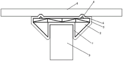
Fig. 1 is a schematic longitudinal sectional view of the pile cap of the present invention installed on a pipe pile.
Fig. 2 is a schematic longitudinal sectional view of the fixing kit according to the present invention.
Fig. 3 is a schematic view of the overall structure of the steel keel in the fixing kit according to the invention.
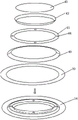
Fig. 4 is an exploded view of the steel keel of the fixing kit according to the present invention.
Fig. 5 is an exploded assembly structure diagram of the external member mold frame according to the present invention.
Fig. 6 is an exploded assembly view of the bottom mold frame of the present invention.
FIG. 7 is an exploded assembly view of the upper plate of the present invention.
In the figure: 1. top plate, 2. fixing external member, 3. tubular pile, 4. ring strip-shaped groove, 5. main plate, 6. ring strip-shaped tenon, 7. fixing
The steel bar keel fixing structure comprises a fixed sleeve, 8 parts of an inner ring wall, 9 parts of an outer ring wall, 10 parts of the lower surface of the fixed sleeve, 11 parts of an inclined ring wall, 12 parts of a steel bar keel and 13 parts of a steel bar keel.
The structure comprises a tenon stirrup, 14 tenon brackets, 15 upper main board stirrups, 16 lower main board stirrups, 17 upper main board straight reinforcements, 18 lower main board straight reinforcements, 19 main board column reinforcements, 20 upper sleeve stirrups, 21 lower sleeve stirrups, 22 sleeve column reinforcements, 23 sleeve inclined reinforcements and 24.
The steel plate comprises an upper main plate steel mesh, 25 parts of a lower main plate steel mesh, 26 parts of a main plate steel cage, 27 parts of a triangular tenon support frame, 28 parts of an annular tenon steel cage, 29 parts of a right-angled triangle support frame, 30 parts of a sleeve steel cage, 31 parts of diagonal ribs, 32 parts of a bottom mold frame, 33 parts of a middle cylinder frame, 34 parts of an upper mold plate, 35 parts of a bottom circular plate, 36 parts of an inner circular cone table plate, 37 parts of a central cylinder, 38 parts of an outer circular cone table plate and 39.
The circular ring plate face, 40, the upper circular ring plate face, 41, the upper circular ring plate face, 42, the lower circular ring plate face, 43, the center circular plate face and 44.
Grouting holes, 45 suite mold frame.
Detailed Description
The present invention is further illustrated by the following examples, which are intended to illustrate the invention but not to limit it further, and should not be construed as limiting the scope of the invention.
Example 1.
As shown in fig. 1 and 2, a prefabricated pile cap for a composite foundation is prefabricated, and the pile cap comprises a top plate 1 and a fixing sleeve 2 supported on the lower side surface of the top plate 1, wherein the fixing sleeve 2 is used for being sleeved on the upper end surface of a tubular pile 3, in this embodiment, a ring-shaped groove 4 is formed in the lower surface of the top plate 1, and the groove wall of the ring-shaped groove 4 inclines towards two sides; such a slanted groove facilitates the mounting.
The fixed suite 2 comprises a main board 5, wherein the upper surface of the main board 5 is provided with a ring-strip-shaped tenon 6
The side surfaces of the tenons 6 are inclined towards two sides, and the specification sizes of the ring strip-shaped tenons 6 are matched with that of the ring strip-shaped grooves 4, so that the ring strip-shaped tenons 6 can be embedded into the ring strip-shaped grooves 4; the lower surface of the main board 5 is provided with a fixed sleeve 7, the upper surface of the fixed sleeve 7 and the lower surface of the main board 5 are integrated, an inner ring wall 8 of the fixed sleeve 7 is vertically connected to the lower surface of the main board 5, an outer ring wall 9 of the fixed sleeve 7 is connected to the lower surface of the main board 5 in an inclined manner, the outer edge of the lower surface 10 of the fixed sleeve is connected with the outer ring wall 8 in an inclined manner, and an inclined ring wall 11 is connected between the inner edge of the lower surface 10 of the fixed sleeve and the lower side edge of the inner ring wall 8; the inclined outer ring wall 9 can provide powerful support for the vertical inner ring wall 8, and the inclined ring wall 11 is convenient for mounting the sleeve on the tubular pile; the inner diameter of the fixing sleeve 7 is smaller than the diameter of the annular strip-shaped tenon 6, the inner diameter of the fixing sleeve 7 is slightly larger than the outer diameter of the tubular pile 3, the inner diameter of the fixing sleeve 7 is generally made to be equal to 100.5-102.5% of the outer diameter of the tubular pile 3, and the length of the inner wall of the fixing sleeve 7 is made to be equal to 26-102% of the outer diameter of the tubular pile 3; in this embodiment, the inner diameter of the fixing sleeve 7 is set to be 101% times the outer diameter of the tubular pile 3, and the length of the inner wall of the fixing sleeve 7 is set to be 52% times the outer diameter of the tubular pile 3.
During assembly, the fixing kit 2 is suspended above the installed tubular pile 3 by a lifting appliance, and the fixing sleeve 7 is aligned to the upper end face of the tubular pile 3, so that a small amount of deviation can be allowed due to the inclined annular wall 11; then move down fixed external member 2, insert fixed sleeve 7 package on tubular pile 3 up end, because the internal diameter of fixed sleeve 7 is only 101% times of the external diameter of tubular pile 3 for fixed external member 2 can be more the suit of closing on tubular pile 3, then install roof 1 on the upper surface of fixed external member 2, and make the annular strip recess 4 package inlay on annular strip tenon 6, just so installed the pile cap.
Example 2.
As shown in fig. 2, 3 and 4, the stable support structure of the pile cap comes mainly from the steel keel 12 in the fixing kit 2. The fixed external member 2 is a steel keel concrete component, wherein the steel keel 12 comprises a tenon stirrup 13, a tenon support frame 14, an upper main board stirrup 15, a lower main board stirrup 16, an upper main board straight reinforcement 17, a lower main board straight reinforcement 18, a main board column reinforcement 19, an upper sleeve stirrup 20, a lower sleeve stirrup 21, a sleeve column reinforcement 22 and a sleeve diagonal reinforcement 23.
The upper main board stirrup 15 and the lower main board stirrup 16 are round stirrups of the same size, the two ends of the upper main board straight stirrups 17 of a plurality of are welded on the upper main board stirrup 15 through the center of the upper main board stirrup to form an upper main board reinforcing mesh 24, the two ends of the lower main board straight stirrups 18 of a plurality of are welded on the lower main board stirrup 16 through the center of the lower main board stirrup to form a lower main board reinforcing mesh 25, the two ends of the main board column reinforcements 19 of a plurality of are respectively welded on the upper main board reinforcing mesh 24 and the lower main board reinforcing mesh 25, a diagonal reinforcement 31 is welded on a diagonal in a rectangle formed by two adjacent main board column reinforcements 19 clamped by the upper main board straight stirrups 17 and the lower main board straight reinforcements 18, and a diagonal reinforcement 31 is welded in each rectangle to form a main board reinforcement cage 26.
The tenon bracing frames 14 comprise a left bracing rod and a right bracing rod, one end of each of the left bracing rod and the right bracing rod is welded on the upper main board straight rib 17 in an inclined manner, the other end of each of the left bracing rod and the right bracing rod is welded with the other end of each of the right bracing rod and the left bracing rod, the right bracing rod and a part of the upper main board straight rib 17 jointly form a triangular tenon bracing frame 27, and the triangular tenon bracing frame 27 is vertical to the upper part of the upper main board reinforcing mesh 24, so that two triangular tenon bracing frames 27 in a central symmetry manner are welded on each upper main board straight rib 17; the tenon stirrup 13 is a circular stirrup with a diameter smaller than that of the upper main board stirrup 15, the diameter of the tenon stirrup 13 is equal to the distance between the vertexes of the two triangular tenon brackets 27 on the same upper main board straight rib 17, and the tenon stirrup 13 is directly welded on the vertexes of the triangular tenon brackets 27 to form an annular tenon reinforcement cage 28.
The upper sleeve stirrup 20 and the lower sleeve stirrup 21 are round stirrups with the same size, the diameters of the upper sleeve stirrup 20 and the lower sleeve stirrup 21 are smaller than the diameter of the tenon stirrup 13 and slightly larger than the outer diameter of the tubular pile 3, the diameters of the upper sleeve stirrup 20 and the lower sleeve stirrup 21 are generally made to be 101% -105% times of the outer diameter of the tubular pile 3, and the diameters of the upper sleeve stirrup 20 and the lower sleeve stirrup 21 are made to be 105% times of the outer diameter of the tubular pile 3; the upper sleeve stirrup 20 is welded on the lower main plate reinforcing mesh 25 and is positioned on the same circle center with the lower main plate stirrup 16, the number of the sleeve column reinforcements 22 and the number of the sleeve diagonal reinforcements 23 are the same and are respectively provided, the length of the sleeve column reinforcements 22 is generally made to be 25% -100% times of the outer diameter of the tubular pile 3, and is made to be 50% times in the embodiment; a plurality of the one end welding of sleeve column muscle 22 is on the crosspoint of last sleeve stirrup 20 and lower mainboard straight muscle 18 and perpendicular with lower mainboard reinforcing mesh 25, a plurality of the one end welding of sleeve diagonal muscle 21 is on the crosspoint of lower mainboard stirrup 16 and lower mainboard straight muscle 18 and be the tilt state with lower mainboard reinforcing mesh 25, the other end welding of sleeve column muscle 22 and sleeve diagonal muscle 23 makes sleeve column muscle 22, sleeve diagonal muscle 23 and a part of lower mainboard straight muscle 18 constitute right triangle jointly and prop frame 29, and this right triangle props and props the below that frame 29 is perpendicular to lower mainboard reinforcing mesh 25, lower sleeve stirrup 21 welding is on the welding point of sleeve column muscle 22 and sleeve diagonal muscle 23, namely right triangle props the summit of propping frame 29, constitutes sleeve steel reinforcement cage 30.
The annular tenon steel reinforcement cage 28 on the upper side of the main board steel reinforcement cage 26 and the sleeve steel reinforcement cage 30 on the lower side of the main board steel reinforcement cage jointly form the steel reinforcement keel 12 of the fixed sleeve member 2.
The manufacturing method of the fixing kit 2 comprises the following steps.
Firstly, manufacturing an external assembly mold frame 45 according to design specifications, wherein the external assembly mold frame 45 comprises a bottom mold frame 32, a middle cylinder frame 33 and an upper mold plate 34, the bottom mold frame 32 comprises a bottom circular ring plate 35, an inner annular conical platen 36, a central cylinder 37 and an outer annular conical platen 38, the bottom circular ring plate 35 is mounted at the bottom, the lower edge of the inner annular conical platen 36 is fixedly connected with the inner edge of the bottom circular ring plate 35, the upper edge of the inner annular conical platen 36 is fixedly connected with the lower circular edge of the central cylinder 37, and the lower edge of the outer annular conical platen 38 is fixedly connected with the outer edge of the bottom circular ring plate 35 to form the bottom mold frame 32; the central cylinder 37 may be a hollow cylinder or a solid cylinder.
The intermediate cylinder frame 33 is formed of a cylindrical plate wall.
The upper template 34 comprises a surface circular ring plate 39, an upper circular ring conical bedplate 40, an upper circular ring plate 41, a lower circular ring conical bedplate 42 and a central circular panel 43, wherein a plurality of grouting holes 44 are formed in the upper circular ring plate 41, the inner edge of the surface circular ring plate 39 is fixedly connected with the lower edge of the upper circular ring conical bedplate 40, the upper edge of the upper circular ring conical bedplate 40 is fixedly connected with the outer edge of the upper circular ring plate 41, the inner edge of the upper circular ring plate 41 is fixedly connected with the upper edge of the lower circular ring conical bedplate 42, and the lower edge of the lower circular ring conical bedplate 42 is fixedly connected with the edge of the central circular panel 43, so that the upper template 34 is formed.
And cutting steel bars according to design specifications, and welding the steel bars into the steel bar keel 12.
Thirdly, lubricating oil is smeared on the inner wall surfaces of the bottom die frame 32 and the middle cylinder frame 33, then the middle cylinder frame 33 is placed at the upper end of the bottom die frame 32, and the upper edge of the outer annular conical platen 38 on the bottom die frame 32 is in stable contact with the lower edge of the middle cylinder frame 33; and then distance control shelves are erected on the inner wall surfaces of the bottom circular ring plate 35 and the outer annular cone bedplate 38 of the bottom die frame 32 and the inner wall surface of the middle barrel frame 33, and meanwhile, the distance control shelves are used for fixing the connecting position of the bottom die frame 32 and the middle barrel frame 33.
The steel bar keel 12 is placed in the middle cylinder frame 33 and the bottom die frame 32 and is placed on the distance control shelf.
Fifthly, pouring concrete mortar and vibrating, after the concrete fills the gaps in the steel bar keels 12 and continues to fill the spaces in the bottom mold frame 32 and the middle barrel frame 33, withdrawing the distance control shelf, and continuing vibrating until the upper surface of the poured concrete mortar is flat.
Sixthly, coating lubricating oil on the inner surface of the upper template 34, then covering the upper template 34 on the upper surface of the concrete mortar, enabling the outer edge of the face annular plate 39 of the upper template 34 to be in contact with the upper edge of the middle cylinder frame 33, then grouting and smashing the inner portion of the lower side of the upper annular plate 41 through grouting holes 44, and completing concrete pouring.
And maintaining, removing the upper template 34 and the middle cylinder frame 33 after the concrete reaches the preset strength, and taking out the reinforced keel concrete member to obtain the fixing kit 2.
Claims (7)
1. An assembled pile cap for a composite foundation comprises a top plate and a fixing external member supported on the lower side surface of the top plate, and is characterized in that a ring-shaped groove is formed in the lower surface of the top plate, and the wall of the ring-shaped groove inclines towards two sides;
the fixing kit comprises a main board, wherein the upper surface of the main board is provided with a ring-shaped tenon, the side surfaces of the ring-shaped tenon incline towards two sides, and the ring-shaped tenon is matched with the ring-shaped groove; the lower surface of the main board is provided with a fixing sleeve, the upper surface of the fixing sleeve and the lower surface of the main board are integrated, the inner ring wall of the fixing sleeve is vertically connected to the lower surface of the main board, the outer ring wall of the fixing sleeve is connected to the lower surface of the main board in an inclined manner, the outer side of the lower surface of the fixing sleeve is connected with the outer ring wall in an inclined manner, and an inclined ring wall is connected between the inner side of the lower surface of the fixing sleeve and the lower side of the inner ring wall.
2. The fabricated pile cap for composite foundation according to claim 1, wherein the fixing kit is a steel keel concrete member, wherein the steel keel comprises a tenon stirrup, a tenon support frame, an upper main plate stirrup, a lower main plate stirrup, an upper main plate straight rib, a lower main plate straight rib, a main plate column rib, an upper sleeve stirrup, a lower sleeve stirrup, a sleeve column rib and a sleeve diagonal rib;
the upper main board stirrup and the lower main board stirrup are round stirrups with the same size, two ends of a plurality of upper main board straight stirrups are welded on the upper main board stirrup through the circle center to form an upper main board reinforcing mesh, two ends of a plurality of lower main board straight stirrups are welded on the lower main board stirrup through the circle center to form a lower main board reinforcing mesh, and two ends of a plurality of main board column reinforcements are respectively welded on the upper main board stirrup and the lower main board stirrup to form a main board reinforcing cage;
the tenon support frames comprise a left support rod and a right support rod, one end of each of the left support rod and the right support rod is welded on the straight upper main board rib in an inclined manner, the other end of each of the left support rod and the right support rod is welded with the other end of each of the right support rod and the left support rod, the right support rod and a part of the straight upper main board rib jointly form a triangular tenon support frame, the tenon is perpendicular to the reinforcing steel bar net of the upper main board, and thus two tenon support frames in a central symmetry manner are welded on each straight upper main board rib; the tenon stirrups are round stirrups with diameters smaller than those of the upper main board stirrups, the diameters of the tenon stirrups are equal to the distance between the triangular vertexes of the two tenon brackets on the same upper main board straight reinforcement, and the tenon stirrups are directly welded on the vertexes of the triangular tenon brackets to form an annular tenon reinforcement cage;
the upper sleeve stirrup and the lower sleeve stirrup are round stirrups with the same size, the diameters of the upper sleeve stirrup and the lower sleeve stirrup are smaller than the diameter of the tenon stirrup and slightly larger than the outer diameter of the tubular pile, the upper sleeve stirrup is welded on the lower main board reinforcing mesh and positioned on the same circle center with the lower main board stirrup, the sleeve column reinforcements and the sleeve diagonal reinforcements are the same in number and are respectively provided with a plurality of sleeves, one ends of the sleeve column reinforcements are welded on the intersection points of the upper sleeve stirrup and the lower main board straight reinforcement and are perpendicular to the lower main board reinforcing mesh, one ends of the sleeve diagonal reinforcements are welded on the intersection points of the lower main board stirrup and the lower main board straight reinforcement and are inclined to the lower main board reinforcing mesh, the other ends of the sleeve column reinforcements and the sleeve diagonal reinforcements are mutually welded, part of the sleeve column reinforcements, the sleeve diagonal reinforcements and the lower main board straight reinforcements form a right-angled triangle supporting frame together, and the right-angled triangle supporting frame is perpendicular to the lower main board reinforcing mesh, the lower sleeve stirrup is welded on a welding point of the sleeve column rib and the sleeve inclined rib to form a sleeve reinforcement cage;
the tenon steel reinforcement cage of mainboard steel reinforcement cage and mainboard steel reinforcement cage upside and the sleeve steel reinforcement cage of mainboard steel reinforcement cage downside constitute the steel reinforcement fossil fragments of fixed external member jointly.
3. The fabricated pile cap of claim 2, wherein a diagonal rib is welded to a diagonal line in a rectangle formed by two adjacent main plate column ribs sandwiched between the upper main plate straight rib and the lower main plate straight rib.
4. The fabricated pile cap for composite foundations as claimed in claim 3, wherein the inner diameter of the fixing sleeve is smaller than the diameter of the ring-shaped tenon; the inner diameter of the fixing sleeve is slightly larger than the outer diameter of the tubular pile.
5. The fabricated pile cap for composite foundation as claimed in claim 4, wherein the inner diameter of the fixing sleeve is equal to 100.5% -102.5% of the outer diameter of the pipe pile; the diameters of the upper sleeve stirrup and the lower sleeve stirrup are both equal to 101% -105% of the outer diameter of the tubular pile.
6. The fabricated pile cap for composite foundation according to claim 5, wherein the length of the inner wall of the tube of the fixing sleeve is equal to 26% -102% of the outer diameter of the tubular pile; the length of the sleeve column rib is equal to 25% -100% of the outer diameter of the tubular pile.
7. The fabricated pile cap for composite foundations of claim 6, wherein the method of manufacturing the fixing kit comprises the following steps.
Firstly, manufacturing an external member mold frame according to design specifications, wherein the external member mold frame comprises a bottom mold frame, a middle cylinder frame and an upper mold plate, the bottom mold frame comprises a bottom circular ring plate, an inner annular conical platen, a central cylinder and an outer annular conical platen, the bottom circular ring plate is installed at the bottom, the lower edge of the inner annular conical platen is fixedly connected with the inner edge of the bottom circular ring plate, the upper edge of the inner annular conical platen is fixedly connected with the lower circular edge of the central cylinder, and the lower edge of the outer annular conical platen is fixedly connected with the outer edge of the bottom circular ring plate to form the bottom mold frame; the central cylinder can be a hollow cylinder or a solid cylinder; the middle cylinder frame is composed of a cylindrical plate wall; the upper template comprises a face circular ring plate, an upper circular ring cone bedplate, an upper circular ring plate, a lower circular ring cone bedplate and a central circular panel, wherein a plurality of grouting holes are formed in the upper circular ring plate, the inner edge of the face circular ring plate is fixedly connected with the lower edge of the upper circular ring cone bedplate, the upper edge of the upper circular ring cone bedplate is fixedly connected with the outer edge of the upper circular ring plate, the inner edge of the upper circular ring plate is fixedly connected with the upper edge of the lower circular ring cone bedplate, and the lower edge of the lower circular ring cone bedplate is fixedly connected with the edge of the central circular panel to form the upper template.
Cutting steel bars according to set specifications, and welding the steel bar keel into the fixed external member.
Thirdly, lubricating oil is smeared on the inner wall surfaces of the bottom die frame and the middle cylinder frame, then the middle cylinder frame is placed at the upper end of the bottom die frame, and the upper edge of the outer annular conical platen on the bottom die frame is stably contacted with the lower edge of the middle cylinder frame; and erecting distance control shelves on the inner wall surfaces of the bottom circular ring plate and the outer annular cone bedplate of the bottom die frame and the inner wall surface of the middle cylinder frame, and fixing the connecting positions of the bottom die frame and the middle cylinder frame relatively by the distance control shelves.
And placing the steel bar keel into the middle barrel frame and the bottom die frame, and placing the steel bar keel on the distance control shelf.
Fifthly, pouring concrete mortar and vibrating, after the concrete is filled in the gaps in the steel bar keels and the bottom formwork space is continuously filled, withdrawing the distance control shelf, and continuously vibrating until the upper surface is flat.
Sixthly, coating lubricating oil on the inner surface of the upper template, covering the upper template on the upper surface of the concrete mortar, enabling the outer edge of the surface circular ring plate of the upper template to be in contact with the upper edge of the middle cylinder frame, and then grouting and vibrating the inner part of the circular ring plate through a grouting hole to finish concrete pouring.
And maintaining the steel bar keel concrete, removing the upper template and the middle cylinder frame after the concrete reaches the preset strength, and taking out the steel bar keel concrete member to obtain the fixing kit.
Priority Applications (1)
| Application Number | Priority Date | Filing Date | Title |
|---|---|---|---|
| CN202210377252.0A CN114753350A (en) | 2022-04-11 | 2022-04-11 | Assembled pile cap for composite foundation |
Applications Claiming Priority (1)
| Application Number | Priority Date | Filing Date | Title |
|---|---|---|---|
| CN202210377252.0A CN114753350A (en) | 2022-04-11 | 2022-04-11 | Assembled pile cap for composite foundation |
Publications (1)
| Publication Number | Publication Date |
|---|---|
| CN114753350A true CN114753350A (en) | 2022-07-15 |
Family
ID=82328876
Family Applications (1)
| Application Number | Title | Priority Date | Filing Date |
|---|---|---|---|
| CN202210377252.0A Withdrawn CN114753350A (en) | 2022-04-11 | 2022-04-11 | Assembled pile cap for composite foundation |
Country Status (1)
| Country | Link |
|---|---|
| CN (1) | CN114753350A (en) |
Cited By (1)
| Publication number | Priority date | Publication date | Assignee | Title |
|---|---|---|---|---|
| CN115095045A (en) * | 2022-07-29 | 2022-09-23 | 中铁第四勘察设计院集团有限公司 | Full-assembly type passenger platform wall |
-
2022
- 2022-04-11 CN CN202210377252.0A patent/CN114753350A/en not_active Withdrawn
Cited By (1)
| Publication number | Priority date | Publication date | Assignee | Title |
|---|---|---|---|---|
| CN115095045A (en) * | 2022-07-29 | 2022-09-23 | 中铁第四勘察设计院集团有限公司 | Full-assembly type passenger platform wall |
Similar Documents
| Publication | Publication Date | Title |
|---|---|---|
| CN108457421B (en) | Manufacturing die and manufacturing method of assembled reinforced concrete U-shaped frame beam | |
| JPH08170340A (en) | Pedestal structure and method of pedestal construction | |
| CN106088330A (en) | The assembling frame beam printed based on 3D and the attachment structure of frame column and construction method thereof | |
| CN113585053B (en) | Prefabricated assembled concrete-filled steel tube pier with out-of-site tension prestress and construction method thereof | |
| CN108643219B (en) | Static pressure miniature pile foundation of anchor rod of assembled power transmission line and construction method of static pressure miniature pile foundation | |
| CN111945879B (en) | Double-steel-plate bolt connection full-assembly type column joint and construction method and calculation method thereof | |
| CN114753350A (en) | Assembled pile cap for composite foundation | |
| CN104790383B (en) | A kind of upright column pile for foundation pit | |
| KR101904763B1 (en) | Coping having Precast Empty Coping Structure, and Constructing Method thereof | |
| CN210459769U (en) | Prefabricated hollow column and assembled concrete column | |
| CN209907420U (en) | Wet joint structure among bridge pier, bearing platform and pile foundation | |
| CN111663521A (en) | Club-footed pile for building immersed tube | |
| CN213978605U (en) | Assembled pier stud connection structure | |
| CN215518328U (en) | Hollow pier diaphragm plate device convenient to install | |
| CN213572930U (en) | Self-locking hinged elevator shaft construction platform device | |
| CN110805141B (en) | Connecting device and method for steel pipe column and shock insulation support after jacking of building | |
| CN109898540B (en) | Wet joint structure among bridge pier, bearing platform and pile foundation and construction process thereof | |
| CN210288522U (en) | Dam foundation rock mass reinforced structure based on prefabricated hollow pile | |
| CN210067523U (en) | Umbrella-type ground storehouse roof reinforcing apparatus that backs to | |
| CN111733691A (en) | Connecting structure and method for prefabricated cylinder and pile foundation | |
| CN105297759A (en) | Framework structure of pile and pillar bearing platform | |
| CN212452268U (en) | Connecting structure of prefabricated cylinder and pile foundation | |
| CN220203007U (en) | RCS structure multi-elevation steel girder combined structure | |
| CN111456325A (en) | Modular composite column and construction method thereof | |
| CN214574083U (en) | High formwork foundation structure |
Legal Events
| Date | Code | Title | Description |
|---|---|---|---|
| PB01 | Publication | ||
| PB01 | Publication | ||
| SE01 | Entry into force of request for substantive examination | ||
| SE01 | Entry into force of request for substantive examination | ||
| WW01 | Invention patent application withdrawn after publication |
Application publication date: 20220715 |
|
| WW01 | Invention patent application withdrawn after publication |