CN114749253A - Reduce small particle solid crushing apparatus of material loss - Google Patents
Reduce small particle solid crushing apparatus of material loss Download PDFInfo
- Publication number
- CN114749253A CN114749253A CN202210527199.8A CN202210527199A CN114749253A CN 114749253 A CN114749253 A CN 114749253A CN 202210527199 A CN202210527199 A CN 202210527199A CN 114749253 A CN114749253 A CN 114749253A
- Authority
- CN
- China
- Prior art keywords
- crushing
- rod
- return spring
- cone
- material loss
- Prior art date
- Legal status (The legal status is an assumption and is not a legal conclusion. Google has not performed a legal analysis and makes no representation as to the accuracy of the status listed.)
- Granted
Links
Images


Classifications
-
- B—PERFORMING OPERATIONS; TRANSPORTING
- B02—CRUSHING, PULVERISING, OR DISINTEGRATING; PREPARATORY TREATMENT OF GRAIN FOR MILLING
- B02C—CRUSHING, PULVERISING, OR DISINTEGRATING IN GENERAL; MILLING GRAIN
- B02C19/00—Other disintegrating devices or methods
-
- B—PERFORMING OPERATIONS; TRANSPORTING
- B02—CRUSHING, PULVERISING, OR DISINTEGRATING; PREPARATORY TREATMENT OF GRAIN FOR MILLING
- B02C—CRUSHING, PULVERISING, OR DISINTEGRATING IN GENERAL; MILLING GRAIN
- B02C23/00—Auxiliary methods or auxiliary devices or accessories specially adapted for crushing or disintegrating not provided for in preceding groups or not specially adapted to apparatus covered by a single preceding group
-
- Y—GENERAL TAGGING OF NEW TECHNOLOGICAL DEVELOPMENTS; GENERAL TAGGING OF CROSS-SECTIONAL TECHNOLOGIES SPANNING OVER SEVERAL SECTIONS OF THE IPC; TECHNICAL SUBJECTS COVERED BY FORMER USPC CROSS-REFERENCE ART COLLECTIONS [XRACs] AND DIGESTS
- Y02—TECHNOLOGIES OR APPLICATIONS FOR MITIGATION OR ADAPTATION AGAINST CLIMATE CHANGE
- Y02W—CLIMATE CHANGE MITIGATION TECHNOLOGIES RELATED TO WASTEWATER TREATMENT OR WASTE MANAGEMENT
- Y02W30/00—Technologies for solid waste management
- Y02W30/50—Reuse, recycling or recovery technologies
- Y02W30/62—Plastics recycling; Rubber recycling
Abstract
The invention relates to crushing equipment, in particular to micro-particle solid crushing equipment capable of reducing material loss. The invention provides a micro-particle solid crushing device which can be used for crushing feed in a diversified manner, improves the crushing efficiency and the crushing effect, and can shake and scrape the feed from a device at the same time, so that the material loss is reduced. The invention provides a micro-particle solid crushing device for reducing material loss, which comprises a first support frame, an installation frame, a crushing barrel and the like; the left and right sides of smashing the bucket all is connected with first support frame, and the upside of smashing the bucket is connected with the installing frame. Make crushing awl rotatory through the drive of first motor, make crushing awl reciprocate through the cooperation of recess and lug to carry out diversified crushing operation, both improved kibbling efficiency and improved kibbling effect, will attach to the fodder on crushing awl simultaneously and shake down, scrape down the fodder that will attach to on the spiral guide slot, reduce material loss.
Description
Technical Field
The invention relates to crushing equipment, in particular to micro-particle solid crushing equipment capable of reducing material loss.
Background
In food processing or medicinal material processing, reducing mechanism can be used usually to come to polish the material and smash, the last material application after will smashing is in other aspects, at the in-process that uses this kind of reducing mechanism processing material, because the material can be attached to on the device after being smashed, get off for a long time, lead to unnecessary extravagant easily, and some materials go mildy and foul easily, thereby can bring unnecessary for the operating personnel troublesome, and present reducing mechanism can not solve this technical problem again well, only can clear up the interior adnexed material of device through the manual work, the cleaning operation is more troublesome.
For example, a solid particle chemical material crushing and recycling device disclosed in patent publication No. CN109718896B and publication No. 20201201 comprises a support frame, wherein a crushing device is arranged at the top of the support frame, and the crushing device is used for performing primary crushing operation on solid particles; the grinding device is arranged in the support frame and used for grinding solid particles again, so that the grinding effect of the grinding and recycling device is improved; the bottom end of the grinding device is provided with a sliding plate, and the sliding plate is provided with a blanking port; the lower end of the sliding plate is provided with a conveying device; and a discharge hole is formed in the side surface of the bottom end of the support frame. This solid particle chemical material smashes recovery unit can carry out abundant crushing to the material of caking when carrying out kibbling to granule material, but the fodder is smashed to the ground that can't diversification, smashes the effect less ideal, and efficiency is lower to the fodder still attaches to on the device easily.
According to the shortcoming that exists among the above-mentioned prior art, design out one kind especially and can overcome prior art shortcoming and smash the fodder in a diversified way, both improved kibbling efficiency and improved kibbling effect, can also shake down the fodder from the device simultaneously and scrape down the tiny particle solid crushing apparatus of reduction material loss.
Disclosure of Invention
The invention aims to overcome the defects that the feed cannot be variously crushed, the crushing effect is not ideal, the efficiency is low, and the feed is still easily attached to a device in the prior art, and the technical problem to be solved is to provide the micro-particle solid crushing equipment which can variously crush the feed, not only improve the crushing efficiency, but also improve the crushing effect, and can shake and scrape the feed from the device to reduce the material loss.
In order to solve the technical problem, the invention provides micro-particle solid crushing equipment for reducing material loss, which comprises a first support frame, an installation frame, a top cover, a crushing barrel, a crushing mechanism, a pressing mechanism and a scraping mechanism, wherein the first support frame is connected to the left side and the right side of the crushing barrel, the installation frame is connected to the upper side of the crushing barrel, the top cover is connected to the inner side of the upper part of the installation frame, the crushing mechanism for crushing materials is arranged on the first support frame, the pressing mechanism for crushing materials is arranged on the top cover, and the scraping mechanism for scraping materials is arranged on the crushing mechanism.
Preferably, rubbing crusher constructs including the second support frame, first motor, the arris pole, smash the awl, first reset spring and sprue, be connected with the second support frame between the lower part of two first support frames, the first motor that is used for power take off is installed to the middle part upside of second support frame, be connected with the arris pole on the output shaft of first motor, the upper end slidingtype cover of arris pole is equipped with and is located inside and the bellied crushing awl that makes progress in crushing bucket, the lower part slidingtype of smashing the awl is equipped with and is used for the sprue of plugging up in the clearance between crushing bucket and the crushing awl, be connected with first reset spring between sprue and the crushing awl.
Preferably, the mechanism pushes down including the mounting panel, the slide bar, second reset spring and lug, the upside of smashing the awl is connected with the slide bar that the slidingtype runs through in the top cap, be connected with between slide bar and the top cap around establishing the second reset spring in the slide bar outside, the upside of slide bar is opened has the round and is the even recess that sets up in interval, the middle part upside of top cap is connected with and surrounds the mounting panel in the slide bar top, the interior top side interval of mounting panel is connected with the round evenly and is the even lug that sets up in interval and contact with the recess.
Preferably, scrape material mechanism including third reset spring, the slider, fourth reset spring and scrape the pole, the inboard interval of smashing the bucket is opened uniformly has five helical guideway that are used for guiding the material flow direction, the upper portion outside interval of smashing the awl is equipped with the slider in the sliding mode uniformly, be connected with third reset spring between slider and the smashing the awl, the inside slidingtype of slider is equipped with scrapes the pole with the contact of helical guideway, scrape and be connected with fourth reset spring between pole and the slider, the torsion of first motor is greater than fourth reset spring's elasticity.
Preferably, still including the mechanism of blowing that is used for making things convenient for the unloading, the mechanism of blowing is including the second motor, the straight-teeth gear, annular fan circle and interior ring gear, and the downside rotary type of top cap is equipped with and is used for making the annular fan circle of circulation of air, and the inboard of annular fan circle is connected with interior ring gear, and the second motor that is used for power take off and output shaft rotary type to run through in the top cap is installed to the left part of top cap, be connected with on the output shaft of second motor with interior ring gear meshing's straight-teeth gear.
Preferably, still including being used for the knocking mechanism who conveniently unloads, knocking mechanism is including the connecting plate, the baffle, the wedge, strike pole and fifth reset spring, the upper portion outside interval of smashing the bucket is connected with six baffles uniformly, the lower part slidingtype of baffle is run through have be used for striking smash the bucket and with smash the pole that strikes of bucket contact, strike and be connected with between pole and the baffle around establishing the fifth reset spring who strikes the pole outside, the upper portion of striking the pole be connected with installing frame sliding type complex wedge, the downside interval of ring sector circle is connected with six evenly and is used for extrudeing the wedge and with installing frame sliding type complex connecting plate.
Preferably, still including the fine grinding mechanism that is used for further smashing the material, fine grinding mechanism is including polishing bucket, the awl of polishing and promoting the frame, and the downside of smashing the bucket is connected with the bucket of polishing, and the middle part slidingtype cover of arris pole is equipped with the awl of polishing that is located the bucket inside of polishing, and the upper portion of the awl of polishing is connected with the promotion frame that is used for promoting the sprue.
Preferably, the grinding machine further comprises an adjusting mechanism used for assisting the fine grinding mechanism, the adjusting mechanism comprises a fixing plate, a screw rod and a sliding disc, the fixing plate is connected to the upper side of the right portion of the second supporting frame, the screw rod is connected to the upper portion of the fixing plate in a penetrating mode through threads, and the sliding disc in sliding fit with the grinding cone is connected to the upper portion of the screw rod.
On the basis of overcoming the defects of the prior art, the invention can also achieve the following beneficial effects:
1. make crushing awl rotatory through the drive of first motor, make crushing awl reciprocate through the cooperation of recess and lug to carry out diversified crushing operation, both improved kibbling efficiency and improved kibbling effect, will attach to the fodder on crushing awl simultaneously and shake down, will attach to the fodder on spiral guide slot and scrape down, reduce material loss.
2. Through the rotation of second motor drive annular fan circle to this blows the fodder downstream on smashing the awl, thereby improves the speed of unloading, simultaneously after smashing the fodder, also can make the fodder downstream after the part is smashed, and then makes the fodder pile up at the interior bottom of smashing the bucket sooner.
3. So that the knocking rod knocks the crushing barrel, the crushing barrel can shake immediately, and then feed blocked on the spiral guide groove is scattered, thereby improving the discharging speed, further avoiding the phenomenon that the feed is always blocked on the spiral guide groove and further avoiding waste.
4. Push the pushing frame rebound through pushing away the frame, and then conveniently carry out the operation of unloading of smashing the bucket, further grind kibbling operation to the fodder through the cooperation of the awl of polishing and the bucket of polishing to further improve kibbling effect.
5. The screw rod is rotated, and the screw rod can drive the grinding cone through the sliding disc to move to conveniently make the grinding cone correspond to or stagger with the grinding barrel, and in addition, the mode through screw rod and fixed plate threaded connection can reach the effect of auto-lock, thereby avoids the unexpected landing of grinding barrel, has increased the stability of this device.
Drawings
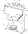
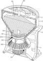
Fig. 1 is a schematic perspective view of the present invention.
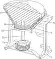
Fig. 2 is a schematic perspective view of a portion of the pressing mechanism of the present invention.
Figure 3 is a cross-sectional view of a first partial body configuration of the shredder mechanism of the present invention.
Figure 4 is a cross-sectional view of a second partial body configuration of the shredder mechanism of the present invention.
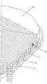
Fig. 5 is a sectional view of a first partially integral construction of the scraping mechanism of the invention.
Fig. 6 is a sectional view of a second partially integral construction of the scraping mechanism of the invention.
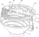
Fig. 7 is a partial perspective sectional view of the blowing mechanism of the present invention.
Fig. 8 is a cross-sectional view of a first partial body construction of the rapping mechanism of the present invention.
Fig. 9 is a cross-sectional view of a second partial body construction of the rapping mechanism of the present invention.
FIG. 10 is a cross-sectional view of a first partial body configuration of the fine grinding mechanism of the present invention.
FIG. 11 is a sectional view of a second partial body configuration of the fine grinding mechanism of the present invention.
Fig. 12 is a partial perspective view of the adjusting mechanism of the present invention.
The labels in the figures are: 1-a first support frame, 2-a mounting frame, 3-a top cover, 4-a crushing barrel, 5-a crushing mechanism, 12-a second support frame, 51-a first motor, 52-a prismatic rod, 53-a crushing cone, 54-a first return spring, 55-a block, 6-a pressing mechanism, 61-a mounting plate, 62-a sliding rod, 63-a second return spring, 64-a groove, 65-a bump, 7-a scraping mechanism, 71-a third return spring, 72-a sliding block, 73-a fourth return spring, 74-a scraping rod, 75-a spiral guide groove, 8-a blowing mechanism, 81-a second motor, 82-a straight gear, 83-an annular fan ring, 84-an inner toothed ring, 9-a knocking mechanism, 91-a connecting plate, 92-guide plate, 93-wedge-shaped plate, 94-knocking rod, 95-fifth return spring, 10-fine grinding mechanism, 101-grinding barrel, 102-grinding cone, 103-pushing frame, 11-adjusting mechanism, 111-fixing plate, 112-screw rod and 113-sliding disk.
Detailed Description
The invention is further described below with reference to the figures and examples.
Example 1
The utility model provides a reduce small particle solid crushing apparatus of material loss, as shown in fig. 1 and fig. 3, including first support frame 1, installing frame 2, top cap 3, smash bucket 4, rubbing crusher constructs 5, push down mechanism 6 and scrape material mechanism 7, the left and right sides of smashing bucket 4 all bolted connection has first support frame 1, the upside welding of smashing bucket 4 has installing frame 2, the inboard bolted connection in upper portion of installing frame 2 has top cap 3, be provided with rubbing crusher constructs 5 that is used for smashing the material on the first support frame 1, be provided with push down mechanism 6 that is used for the crushing material on the top cap 3, be provided with scraping material mechanism 7 that is used for scraping the material on rubbing crusher constructs 5.
As shown in fig. 3, 4 and 11, the crushing mechanism 5 includes a second support frame 12, a first motor 51, a ridge rod 52, a crushing cone 53, a first return spring 54 and a blocking block 55, the second support frame 12 is bolted between the lower parts of the two first support frames 1, the first motor 51 for power output is installed on the upper side of the middle part of the second support frame 12 in a screw connection mode, the ridge rod 52 is connected to an output shaft of the first motor 51, the crushing cone 53 which is located inside the crushing barrel 4 and protrudes upwards at the upper part is slidably sleeved on the upper end of the ridge rod 52, the blocking block 55 which is used for blocking the gap between the crushing barrel 4 and the crushing cone 53 is slidably arranged at the lower part of the crushing cone 53, and the first return spring 54 is connected between the blocking block 55 and the crushing cone 53.
As shown in fig. 2 and 3, the pressing mechanism 6 includes an installation plate 61, a slide rod 62, a second return spring 63 and a protrusion 65, the slide rod 62 slidably penetrating the top cover 3 is bolted on the upper side of the crushing cone 53, the second return spring 63 wound on the outer side of the slide rod 62 is connected between the slide rod 62 and the top cover 3, a circle of grooves 64 uniformly arranged at intervals is opened on the upper side of the slide rod 62, the installation plate 61 surrounding the slide rod 62 is bolted on the upper side of the middle part of the top cover 3, and a circle of protrusions 65 uniformly arranged at intervals and contacting the grooves 64 are uniformly connected on the inner top side of the installation plate 61 at intervals.
As shown in fig. 4-6, the scraping mechanism 7 includes a third return spring 71, a sliding block 72, a fourth return spring 73 and a scraping rod 74, five spiral guide grooves 75 for guiding the material flow direction are uniformly formed at intervals on the inner side of the crushing barrel 4, the sliding block 72 is uniformly arranged at intervals on the outer side of the upper portion of the crushing cone 53 in a sliding manner, the third return spring 71 is connected between the sliding block 72 and the crushing cone 53, the scraping rod 74 contacting with the spiral guide grooves 75 is slidably arranged inside the sliding block 72, the fourth return spring 73 is connected between the scraping rod 74 and the sliding block 72, and the torsion of the first motor 51 is greater than the elastic force of the fourth return spring 73.
Initially, the block 55 is blocked in the gap between the crushing barrel 4 and the crushing cone 53, when the operator needs to apply the device to the technology of crushing small materials to reduce material loss, firstly, the operator pours the materials into the mounting frame 2 through the top cover 3, the materials flow into the gap between the crushing barrel 4 and the crushing cone 53 along the crushing cone 53, then the operator starts the first motor 51, the output shaft of the first motor 51 drives the crushing cone 53 to rotate through the ridge rod 52, the crushing cone 53 can grind and crush the materials through the crushing barrel 4 in the rotating process, the friction force with the feed can be increased through the spiral guide groove 75, so as to ensure the crushing effect, in the process of grinding and crushing the materials, the crushing cone 53 can also drive the slide rod 62 to rotate, the slide rod 62 can continuously move up and down under the matching of the groove 64 and the convex block 65, the second return spring 63 is adaptively deformed immediately, the sliding rod 62 moves up and down to drive the crushing cone 53 to move up and down, the crushing cone 53 rolls and crushes the feed in the process of moving up and down, so as to further crush the feed in a diversified manner, the crushing efficiency is improved, the crushing effect is improved, meanwhile, the feed attached to the crushing cone 53 is shaken, in addition, the crushing cone 53 drives the scraping rod 74 to rotate through the sliding block 72 in the rotating process, the scraping rod 74 gradually slides downwards along the spiral guide groove 75 in the rotating process, the third return spring 71 compresses and stores force, the scraping rod 74 scrapes the feed powder remained in the spiral guide groove 75 in the downwards moving process, so that the crushed feed is gathered at the inner bottom of the crushing barrel 4, the feed is prevented from being always blocked on the spiral guide groove 75, the waste phenomenon is avoided, and the loss of the material is reduced, the scraping rod 74 is separated from the spiral guide groove 75 in the process of sliding downwards along the spiral guide groove 75, the third return spring 71 is reset, the slide block 72 moves upwards along the crushing cone 53 under the action of the reset of the third return spring 71, in the process, the crushing barrel 4 extrudes the slide block 72 to move inwards, the fourth return spring 73 is compressed, the slide block 72 continues to move upwards to be separated from the crushing barrel 4, the fourth return spring 73 is reset, the slide block 72 moves outwards under the action of the reset of the fourth return spring 73 to be clamped into the spiral guide groove 75 again, the reciprocating operation can be carried out all the time, after the operation of crushing the feed is finished, an operator closes the first motor 51, pulls the block 55 downwards, the first return spring 54 stretches to enable the block 55 to be separated from the gap between the crushing barrel 4 and the crushing cone 53, and the crushed feed can flow out from the gap between the crushing barrel 4 and the crushing cone 53, therefore, the discharging operation is carried out, after the discharging operation is finished, the operator loosens the blocking piece 55, the first return spring 54 is reset, the blocking piece 55 can move upwards under the reset action of the first return spring 54 to reset and block the gap between the crushing barrel 4 and the crushing cone 53 again, and the device is used.
Example 2
On the basis of embodiment 1, as shown in fig. 1 and 7, the blanking device further comprises a blowing mechanism 8 for facilitating blanking, the blowing mechanism 8 comprises a second motor 81, a spur gear 82, an annular fan ring 83 and an inner gear ring 84, the annular fan ring 83 for circulating air is rotatably arranged on the lower side of the top cover 3, the inner gear ring 84 is connected to the inner side of the annular fan ring 83, the second motor 81 for outputting power and having an output shaft rotatably penetrating through the top cover 3 is mounted on the left portion of the top cover 3 in a screw connection mode, and the spur gear 82 meshed with the inner gear ring 84 is connected to the output shaft of the second motor 81.
When the operation of unloading is being carried out, the operator starts second motor 81, the output shaft of second motor 81 can drive spur gear 82 rotatory and the meshing of interior ring gear 84, interior ring gear 84 can drive annular fan circle 83 rotatory, annular fan circle 83 can blow the fodder downstream on smashing awl 53 at rotatory in-process, thereby improve the speed of unloading, simultaneously after smashing the fodder, also can make the part by the fodder downstream after smashing, and then make the fodder pile up at the interior bottom of smashing bucket 4 sooner, after the operation of smashing the fodder is accomplished afterwards, the operator closes second motor 81, with this use of accomplishing air-blowing mechanism 8.
Example 3
On the basis of embodiment 2, as shown in fig. 1, 8 and 9, the device further comprises a knocking mechanism 9 for facilitating discharging, wherein the knocking mechanism 9 comprises a connecting plate 91, a guide plate 92, a wedge plate 93, a knocking rod 94 and a fifth return spring 95, six guide plates 92 are bolted on the outer side of the upper portion of the crushing barrel 4 at intervals uniformly, the knocking rod 94 for knocking the crushing barrel 4 and contacting with the crushing barrel 4 penetrates through the lower portion of the guide plate 92 in a sliding manner, the fifth return spring 95 wound on the outer side of the knocking rod 94 is connected between the knocking rod 94 and the guide plate 92, the wedge plate 93 in sliding fit with the mounting frame 2 is bolted on the upper portion of the knocking rod 94, and six connecting plates 91 for extruding the wedge plate 93 and fitting with the mounting frame 2 are welded on the lower side of the annular fan ring 83 at intervals uniformly.
Initially, the knocking rod 94 is in contact with the crushing barrel 4, the annular fan ring 83 drives the connecting plate 91 to rotate when rotating, the connecting plate 91 can extrude the wedge plate 93 to move downwards in the rotating process, the wedge plate 93 can drive the knocking rod 94 to move downwards to be far away from the crushing barrel 4, the fifth return spring 95 compresses to store force, the connecting plate 91 rotates continuously to loosen the wedge plate 93, the fifth return spring 95 resets, the knocking rod 94 can move upwards under the reset effect of the fifth return spring 95 to be in contact with the crushing barrel 4 again, so that the knocking lever 94 knocks the pulverizing barrel 4, the pulverizing barrel 4 is shaken immediately, thereby dispersing the fodder jammed in the spiral guide groove 75 to increase the discharging speed, the wedge plate 93 is pressed again by the continuous rotation of the connection plate 91, the crushing barrel 4 can be continuously beaten by reciprocating in this way, and the beating effect is ensured.
Example 4
On the basis of embodiment 3, as shown in fig. 1 and 10, the device further comprises a fine grinding mechanism 10 for further grinding the material, the fine grinding mechanism 10 comprises a grinding barrel 101, a grinding cone 102 and a pushing frame 103, the grinding barrel 101 is bolted to the lower side of the grinding barrel 4, the grinding cone 102 located inside the grinding barrel 101 is slidably sleeved in the middle of the ridge rod 52, and the pushing frame 103 for pushing the block 55 is welded to the upper part of the grinding cone 102.
Initially, the grinding cone 102 is staggered with the grinding barrel 101, after the feed is ground, an operator firstly makes the first motor 51 in a closed state, then moves the grinding cone 102 upwards to make the grinding cone 102 correspond to the grinding barrel 101, the grinding cone 102 moves upwards to drive the pushing frame 103 to move upwards, the pushing frame 103 can squeeze the pushing frame 103 to move upwards in the process of moving upwards, so that the ground feed flows out of a gap between the grinding barrel 4 and the grinding cone 53 to the grinding cone 102, the unloading operation of the grinding barrel 4 is further conveniently carried out, then the operator starts the first motor 51 again, the edge rod 52 rotates to drive the grinding cone 102 to rotate, the grinding cone 102 further grinds and grinds the feed in the rotating process by matching with the grinding barrel 101, the grinding effect is further improved, after the grinding cone 102 is used, the operator turns off the first motor 51, pulls the grinding cone 102 downward, and makes the grinding cone 102 and the grinding barrel 101 staggered, and the feed crushed in the grinding barrel 101 immediately falls out of the grinding barrel 101, thereby completing the further crushing operation.
Example 5
On the basis of the embodiment 4, as shown in fig. 1, fig. 11 and fig. 12, the device further includes an adjusting mechanism 11 for assisting the fine grinding mechanism 10, the adjusting mechanism 11 includes a fixing plate 111, a screw rod 112 and a sliding disk 113, the fixing plate 111 is bolted to the upper side of the right portion of the second support frame 12, the screw rod 112 is connected to the upper portion of the fixing plate 111 through a penetrating type screw thread, and the sliding disk 113 in sliding fit with the grinding cone 102 is bolted to the upper portion of the screw rod 112.
The operator rotates screw rod 112, screw rod 112 can drive sliding disc 113 rebound, sliding disc 113 can drive polishing awl 102 rebound, it corresponds with the bucket 101 of polishing to make this conveniently, in addition, the mode through screw rod 112 and 111 threaded connection of fixed plate can reach the effect of auto-lock, thereby avoid polishing the unexpected landing of bucket 101, the stability of this device has been increased, last operator antiport screw rod 112, screw rod 112 can drive polishing awl 102 rebound through sliding disc 113, the operation of unloading of bucket 101 of polishing with this conveniently.
The above examples are merely representative of preferred embodiments of the present invention, and the description thereof is more specific and detailed, but not to be construed as limiting the scope of the present invention. It should be noted that, for those skilled in the art, various changes, modifications and substitutions can be made without departing from the spirit of the present invention, and these are all within the scope of the present invention. Therefore, the protection scope of the present patent shall be subject to the appended claims.
Claims (8)
1. The utility model provides a reduce small particle solid crushing apparatus of material loss, including first support frame (1), installing frame (2), top cap (3) and crushing bucket (4), the left and right sides of crushing bucket (4) all is connected with first support frame (1), the upside of crushing bucket (4) is connected with installing frame (2), the upper portion inboard of installing frame (2) is connected with top cap (3), a serial communication port, still including rubbing crusher constructs (5), push down mechanism (6) and scrape material mechanism (7), be provided with rubbing crusher structure (5) on first support frame (1), be provided with push down mechanism (6) on top cap (3), be provided with on rubbing crusher constructs (5) and scrape material mechanism (7).
2. The fine particle solid crushing equipment for reducing the material loss according to claim 1, wherein the crushing mechanism (5) comprises a second support frame (12), a first motor (51), a ridge rod (52), a crushing cone (53), a first return spring (54) and a blocking block (55), the second support frame (12) is connected between the lower parts of the two first support frames (1), the first motor (51) is installed on the upper side of the middle part of the second support frame (12), the ridge rod (52) is connected onto an output shaft of the first motor (51), the crushing cone (53) is sleeved on the upper end of the ridge rod (52) in a sliding mode, the blocking block (55) is arranged on the lower part of the crushing cone (53) in a sliding mode, and the first return spring (54) is connected between the blocking block (55) and the crushing cone (53).
3. The fine particle solid crushing equipment for reducing the material loss as claimed in claim 2, wherein the pressing mechanism (6) comprises a mounting plate (61), a slide rod (62), a second return spring (63) and a lug (65), the slide rod (62) which slidably penetrates through the top cover (3) is connected to the upper side of the crushing cone (53), the second return spring (63) is connected between the slide rod (62) and the top cover (3), a circle of groove (64) is formed in the upper side of the slide rod (62), the mounting plate (61) is connected to the upper side of the middle part of the top cover (3), and a circle of lug (65) is uniformly connected to the inner top side of the mounting plate (61) at intervals.
4. The fine particle solid crushing equipment for reducing the material loss according to claim 3, wherein the scraping mechanism (7) comprises a third return spring (71), a sliding block (72), a fourth return spring (73) and a scraping rod (74), spiral guide grooves (75) are uniformly formed in the inner side of the crushing barrel (4) at intervals, the sliding block (72) is uniformly arranged on the outer side of the upper part of the crushing cone (53) in a sliding mode at intervals, the third return spring (71) is connected between the sliding block (72) and the crushing cone (53), the scraping rod (74) in contact with the spiral guide grooves (75) is arranged in the sliding block (72), the fourth return spring (73) is connected between the scraping rod (74) and the sliding block (72), and the torsion force of the first motor (51) is larger than the elastic force of the fourth return spring (73).
5. The fine particle solid crushing equipment for reducing the material loss according to claim 4, further comprising a blowing mechanism (8), wherein the blowing mechanism (8) comprises a second motor (81), a straight gear (82), an annular fan ring (83) and an inner gear ring (84), the annular fan ring (83) is rotatably arranged on the lower side of the top cover (3), the inner gear ring (84) is connected to the inner side of the annular fan ring (83), the second motor (81) with an output shaft rotatably penetrating through the top cover (3) is installed on the left portion of the top cover (3), and the straight gear (82) meshed with the inner gear ring (84) is connected to the output shaft of the second motor (81).
6. The small particle solid crushing device capable of reducing the material loss as claimed in claim 5, further comprising a knocking mechanism (9), wherein the knocking mechanism (9) comprises a connecting plate (91), a guide plate (92), a wedge-shaped plate (93), a knocking rod (94) and a fifth return spring (95), six guide plates (92) are uniformly connected to the outer side of the upper portion of the crushing barrel (4) at intervals, the knocking rod (94) in contact with the crushing barrel (4) penetrates through the lower portion of each guide plate (92) in a sliding manner, the fifth return spring (95) is connected between the knocking rod (94) and the guide plate (92), the wedge-shaped plate (93) in sliding fit with the mounting frame (2) is connected to the upper portion of the knocking rod (94), and six connecting plates (91) in sliding fit with the mounting frame (2) are uniformly connected to the lower side of the annular fan ring (83) at intervals.
7. The fine particle solid crushing equipment for reducing the material loss according to claim 6, further comprising a fine grinding mechanism (10), wherein the fine grinding mechanism (10) comprises a grinding barrel (101), a grinding cone (102) and a pushing frame (103), the grinding barrel (101) is connected to the lower side of the crushing barrel (4), the grinding cone (102) is slidably sleeved in the middle of the ridge rod (52), and the pushing frame (103) is connected to the upper part of the grinding cone (102).
8. The fine particle solid crushing apparatus capable of reducing the material loss according to claim 7, further comprising an adjusting mechanism (11), wherein the adjusting mechanism (11) comprises a fixing plate (111), a screw rod (112) and a sliding disc (113), the fixing plate (111) is connected to the upper side of the right part of the second supporting frame (12), the screw rod (112) is connected to the upper part of the fixing plate (111) in a penetrating and threaded manner, and the sliding disc (113) which is in sliding fit with the grinding cone (102) is connected to the upper part of the screw rod (112).
Priority Applications (1)
| Application Number | Priority Date | Filing Date | Title |
|---|---|---|---|
| CN202210527199.8A CN114749253B (en) | 2022-05-16 | 2022-05-16 | Reduce small particle solid crushing apparatus of material loss |
Applications Claiming Priority (1)
| Application Number | Priority Date | Filing Date | Title |
|---|---|---|---|
| CN202210527199.8A CN114749253B (en) | 2022-05-16 | 2022-05-16 | Reduce small particle solid crushing apparatus of material loss |
Publications (2)
| Publication Number | Publication Date |
|---|---|
| CN114749253A true CN114749253A (en) | 2022-07-15 |
| CN114749253B CN114749253B (en) | 2023-03-10 |
Family
ID=82334370
Family Applications (1)
| Application Number | Title | Priority Date | Filing Date |
|---|---|---|---|
| CN202210527199.8A Active CN114749253B (en) | 2022-05-16 | 2022-05-16 | Reduce small particle solid crushing apparatus of material loss |
Country Status (1)
| Country | Link |
|---|---|
| CN (1) | CN114749253B (en) |
Cited By (3)
| Publication number | Priority date | Publication date | Assignee | Title |
|---|---|---|---|---|
| CN115415027A (en) * | 2022-09-06 | 2022-12-02 | 王新媱 | Preparation process of health-care meal replacement powder |
| CN115501940A (en) * | 2022-10-28 | 2022-12-23 | 山东百成新材料科技股份有限公司 | Asphalt homogenizing device and asphalt homogenizing method |
| CN116099638A (en) * | 2023-04-13 | 2023-05-12 | 石家庄迈邦机械设备有限公司 | Crushing machine |
Citations (13)
| Publication number | Priority date | Publication date | Assignee | Title |
|---|---|---|---|---|
| CN208878649U (en) * | 2018-07-12 | 2019-05-21 | 张改义 | A kind of herding grain trough disintegrating apparatus |
| CN209531097U (en) * | 2019-01-29 | 2019-10-25 | 郭婧 | A kind of operating room drug crushing device |
| CN210449446U (en) * | 2019-07-16 | 2020-05-05 | 辽东学院 | Chinese-medicinal material processing is with smashing grinder |
| CN111482259A (en) * | 2020-05-07 | 2020-08-04 | 朱欢 | Smashing device for feed processing and using method thereof |
| CN211563225U (en) * | 2019-10-31 | 2020-09-25 | 中国科学院合肥物质科学研究院 | Crushing, grinding and sieving integrated device with automatic cleaning function |
| CN111889188A (en) * | 2020-07-29 | 2020-11-06 | 夏梦丽雅 | Chicken and duck fodder reducing mechanism |
| CN112547266A (en) * | 2020-11-07 | 2021-03-26 | 罗浩 | Clothing rubber powder stirring and grinding equipment |
| CN213854727U (en) * | 2020-11-11 | 2021-08-03 | 哈尔滨市联丰饲料有限公司 | Fodder superfine grinding device |
| CN113231169A (en) * | 2021-06-11 | 2021-08-10 | 万一 | Biological pharmacy industry medicine tablet grinds into powder equipment |
| CN113351307A (en) * | 2021-06-02 | 2021-09-07 | 温秋英 | Over-and-under type crushing apparatus for flour processing |
| CN113399030A (en) * | 2021-06-15 | 2021-09-17 | 邱贤伟 | Medicament collecting equipment that mills for drugstore |
| CN114405646A (en) * | 2022-01-24 | 2022-04-29 | 黄华柏 | Herbaceous plant solid beverage granule grinding device |
| CN216499898U (en) * | 2021-12-31 | 2022-05-13 | 江苏省徐州技师学院 | A smash sampling device for food quality safety inspection |
-
2022
- 2022-05-16 CN CN202210527199.8A patent/CN114749253B/en active Active
Patent Citations (13)
| Publication number | Priority date | Publication date | Assignee | Title |
|---|---|---|---|---|
| CN208878649U (en) * | 2018-07-12 | 2019-05-21 | 张改义 | A kind of herding grain trough disintegrating apparatus |
| CN209531097U (en) * | 2019-01-29 | 2019-10-25 | 郭婧 | A kind of operating room drug crushing device |
| CN210449446U (en) * | 2019-07-16 | 2020-05-05 | 辽东学院 | Chinese-medicinal material processing is with smashing grinder |
| CN211563225U (en) * | 2019-10-31 | 2020-09-25 | 中国科学院合肥物质科学研究院 | Crushing, grinding and sieving integrated device with automatic cleaning function |
| CN111482259A (en) * | 2020-05-07 | 2020-08-04 | 朱欢 | Smashing device for feed processing and using method thereof |
| CN111889188A (en) * | 2020-07-29 | 2020-11-06 | 夏梦丽雅 | Chicken and duck fodder reducing mechanism |
| CN112547266A (en) * | 2020-11-07 | 2021-03-26 | 罗浩 | Clothing rubber powder stirring and grinding equipment |
| CN213854727U (en) * | 2020-11-11 | 2021-08-03 | 哈尔滨市联丰饲料有限公司 | Fodder superfine grinding device |
| CN113351307A (en) * | 2021-06-02 | 2021-09-07 | 温秋英 | Over-and-under type crushing apparatus for flour processing |
| CN113231169A (en) * | 2021-06-11 | 2021-08-10 | 万一 | Biological pharmacy industry medicine tablet grinds into powder equipment |
| CN113399030A (en) * | 2021-06-15 | 2021-09-17 | 邱贤伟 | Medicament collecting equipment that mills for drugstore |
| CN216499898U (en) * | 2021-12-31 | 2022-05-13 | 江苏省徐州技师学院 | A smash sampling device for food quality safety inspection |
| CN114405646A (en) * | 2022-01-24 | 2022-04-29 | 黄华柏 | Herbaceous plant solid beverage granule grinding device |
Cited By (3)
| Publication number | Priority date | Publication date | Assignee | Title |
|---|---|---|---|---|
| CN115415027A (en) * | 2022-09-06 | 2022-12-02 | 王新媱 | Preparation process of health-care meal replacement powder |
| CN115501940A (en) * | 2022-10-28 | 2022-12-23 | 山东百成新材料科技股份有限公司 | Asphalt homogenizing device and asphalt homogenizing method |
| CN116099638A (en) * | 2023-04-13 | 2023-05-12 | 石家庄迈邦机械设备有限公司 | Crushing machine |
Also Published As
| Publication number | Publication date |
|---|---|
| CN114749253B (en) | 2023-03-10 |
Similar Documents
| Publication | Publication Date | Title |
|---|---|---|
| CN114749253A (en) | Reduce small particle solid crushing apparatus of material loss | |
| US8091473B2 (en) | Juice extractor | |
| CN208727625U (en) | A kind of Brown Alundum raw material block crushing device | |
| CN209222275U (en) | A kind of crushing fine grinding device for pefloxacin mesilate production | |
| CN209155987U (en) | A kind of scraper plate sieving fast-crushing machine | |
| CN111229369B (en) | System of smashing of cellulose ether raw materials for production | |
| JP2019522530A (en) | Squeeze screw, squeeze component and food cooker | |
| CN113171718A (en) | Processing apparatus is used in biological feed processing | |
| CN218190083U (en) | Refined quartz sand production grinder | |
| CN109569850A (en) | A kind of raw material grinding machine | |
| CN112916183B (en) | Preparation processing method of mica functional filler | |
| CN213611798U (en) | Spices raw materials reducing mechanism | |
| CN210230204U (en) | Superfine grinding equipment for solid beverage | |
| CN112774840A (en) | Multistage crushing apparatus of superfine powder for bio-pharmaceuticals | |
| CN218250655U (en) | Pig is rubbing crusher for feed processing | |
| CN109571806A (en) | A kind of phenolaldehyde moulding compound grinding device | |
| CN116273409B (en) | Rose freeze-drying grinder | |
| CN113731609B (en) | Preparation device for preparing high-activity iron-based energetic composite material | |
| CN220242234U (en) | Discharging mechanism for injection molding machine | |
| CN219210120U (en) | Efficient grinding device for producing powdery seasonings | |
| CN218516827U (en) | Rutile titanium dioxide crushing apparatus | |
| CN113617458B (en) | Novel superfine pulverizer | |
| CN217855870U (en) | Mixing arrangement is used in mica production and processing | |
| CN211887870U (en) | Screening machine for filtering conductive graphite powder | |
| CN217774327U (en) | Grain crushing and screening device |
Legal Events
| Date | Code | Title | Description |
|---|---|---|---|
| PB01 | Publication | ||
| PB01 | Publication | ||
| SE01 | Entry into force of request for substantive examination | ||
| SE01 | Entry into force of request for substantive examination | ||
| GR01 | Patent grant | ||
| GR01 | Patent grant |