CN114740887A - Flight body deflection head control method and system capable of generating large-angle deflection - Google Patents
Flight body deflection head control method and system capable of generating large-angle deflection Download PDFInfo
- Publication number
- CN114740887A CN114740887A CN202210325541.6A CN202210325541A CN114740887A CN 114740887 A CN114740887 A CN 114740887A CN 202210325541 A CN202210325541 A CN 202210325541A CN 114740887 A CN114740887 A CN 114740887A
- Authority
- CN
- China
- Prior art keywords
- head
- deflection
- flying body
- angle
- support rods
- Prior art date
- Legal status (The legal status is an assumption and is not a legal conclusion. Google has not performed a legal analysis and makes no representation as to the accuracy of the status listed.)
- Pending
Links
Images


Classifications
-
- G—PHYSICS
- G05—CONTROLLING; REGULATING
- G05D—SYSTEMS FOR CONTROLLING OR REGULATING NON-ELECTRIC VARIABLES
- G05D1/00—Control of position, course, altitude or attitude of land, water, air or space vehicles, e.g. using automatic pilots
- G05D1/10—Simultaneous control of position or course in three dimensions
- G05D1/101—Simultaneous control of position or course in three dimensions specially adapted for aircraft
Landscapes
- Engineering & Computer Science (AREA)
- Aviation & Aerospace Engineering (AREA)
- Radar, Positioning & Navigation (AREA)
- Remote Sensing (AREA)
- Physics & Mathematics (AREA)
- General Physics & Mathematics (AREA)
- Automation & Control Theory (AREA)
- Toys (AREA)
Abstract
Description
技术领域technical field
本发明属于高速飞行控制技术领域,特别是一种应用于管式发射的高超音速制导炮弹、飞行体等飞行体的偏转头控制方法及系统。The invention belongs to the technical field of high-speed flight control, in particular to a deflecting head control method and system for tube-launched hypersonic guided artillery shells, flying bodies and other flying bodies.
背景技术Background technique
偏转头飞行控制为一种独特的控制策略,其通过在空气流中的飞行体整个头部的角度偏转,离开飞行体的中心线,在头部的迎风面和背风面产生不同的空气压力,从而产生控制力,操纵飞行体的飞行姿态,进而改变飞行轨迹,通过偏转头向任意方向偏转来完成飞行体任何方向的飞行路径改变。与目前采用的多舵面控制飞行体相比,在相同的配平攻角飞行情况下,具有高的法向力,更小的空气阻力和舵面偏转角度,而在飞行体的机动性、操纵性和稳定性间达到一个高性能的平衡。在不需要偏转控制时,头部可以回到中心和飞行体轴线一致的位置,由于不需要额外的复杂锁紧和张开机构,尤其适用于管射飞行体的飞行控制。The deflection head flight control is a unique control strategy that produces different air pressures on the windward and leeward sides of the head by angular deflection of the entire head of the flying body in the air flow, away from the centerline of the flying body , so as to generate control force, manipulate the flight attitude of the flying body, and then change the flight trajectory, and complete the flight path change of the flying body in any direction by deflecting the head to any direction. Compared with the current multi-rudder control aircraft, under the same trim angle of attack, it has high normal force, smaller air resistance and rudder deflection angle, while the maneuverability and control of the aircraft A high-performance balance is achieved between performance and stability. When no deflection control is required, the head can be returned to a position consistent with the axis of the flying body. Since no additional complex locking and opening mechanisms are required, it is especially suitable for flight control of tube-firing flying bodies.
目前关于偏砖头控制系统的研究较少,已有的采用斜盘式、智能材料等方案的偏转头控制系统存在偏转角度较小(5度左右)、结构复杂、成本高等缺点,已不能满足大角度偏转和低成本的设计需求,随着偏转头飞行控制的进一步发展,急需针对性的开展适配的偏转头飞行控制系统。At present, there are few researches on the deflecting head control system. The existing deflecting head control systems using swash plate type, intelligent material and other schemes have the disadvantages of small deflection angle (about 5 degrees), complex structure and high cost, which can no longer satisfy With the design requirements of large angle deflection and low cost, with the further development of the deflection head flight control, a targeted and adapted deflection head flight control system is urgently needed.
发明内容SUMMARY OF THE INVENTION
本发明的目的在于提供一种可产生大角度偏转的飞行体偏转头控制方法及系统,以实现飞行体在高速飞行情况下的高效控制。The purpose of the present invention is to provide a method and system for controlling the deflection head of a flying body that can generate large-angle deflection, so as to realize the efficient control of the flying body under the condition of high-speed flight.
实现本发明目的的技术解决方案为:The technical solution that realizes the purpose of the present invention is:
一种可产生大角度偏转的飞行体偏转头控制方法,基于四点支撑方法,采用四个支撑杆和一个万向节把飞行体头部与飞行体主体铰接,其中四个支撑杆的支撑点构成平行四边形,万向节位于平行四边形的中心,通过四个支撑杆的伸缩,使得飞行体头部围绕万向节偏转;A method for controlling the deflection head of a flying body that can produce a large angle of deflection. Based on a four-point support method, four support rods and a universal joint are used to articulate the head of the flying body and the main body of the flying body, wherein the four support rods support The points form a parallelogram, and the universal joint is located in the center of the parallelogram. The head of the flying body is deflected around the universal joint through the expansion and contraction of the four support rods;
其中呈对角的一对支撑杆一个伸出长度△l,则另一个同步缩短长度△l,用于控制飞行体头部的俯仰角δy,呈对角的另一对支撑杆一个伸出长度△k,则另一个同步缩短长度△k,用于控制飞行体头部的偏角δz,四个支撑杆同时进行伸缩完成飞行体头部绕万向节的偏转;从而实现飞行体飞行轨迹的改变。One of the diagonal pair of support rods is extended by a length Δl, and the other is shortened by the length △l simultaneously, which is used to control the pitch angle δ y of the head of the flying body, and the other pair of diagonal support rods is extended by one. If the length △k, the other synchronously shortens the length △k, which is used to control the declination angle δ z of the head of the flying body. change in trajectory.
一种可产生大角度偏转的飞行体偏转头控制系统,包括控制单元、四个支撑杆和一个万向节,所述四个支撑杆和一个万向节连接于飞行体头部与飞行体主体之间;所述四个支撑杆的支撑点构成平行四边形,万向节位于平行四边形的中心;A flying body deflection head control system capable of producing large-angle deflection, comprising a control unit, four support rods and a universal joint, the four support rods and one universal joint are connected to the flying body head and the flying body between the main bodies; the support points of the four support rods form a parallelogram, and the universal joint is located in the center of the parallelogram;
所述控制单元用于控制四个支撑杆的伸缩,使得飞行体头部围绕万向节偏转:其中呈对角的一对支撑杆一个伸出长度△l,则另一个同步缩短长度△l,用于控制飞行体头部的俯仰角δy,呈对角的另一对支撑杆一个伸出长度△k,则另一个同步缩短长度△k,用于控制飞行体头部的偏角δz,四个支撑杆同时进行伸缩完成飞行体头部绕万向节的偏转;用于控制飞行体飞行轨迹的改变,当一个支撑杆完全缩进,呈对角的另一个支撑杆完全伸展,控制伸展的长度,从原理上可以实现近90度的偏转,从而实现较大范围的不同角度的偏转。The control unit is used to control the extension and retraction of the four support rods, so that the head of the flying body is deflected around the universal joint: one of the diagonal pair of support rods is extended by a length of Δl, and the other is shortened by a length of Δl simultaneously, It is used to control the pitch angle δ y of the head of the flying body. One of the other pair of support rods that are diagonally extended has a length Δk, and the other is synchronously shortened by the length Δk, which is used to control the declination angle δ z of the head of the flying body. , the four support rods are telescopic at the same time to complete the deflection of the flight body head around the universal joint; it is used to control the change of the flight path of the flight body. When one support rod is fully retracted, the other diagonal support rod is fully extended, and the control The stretched length can in principle achieve a deflection of nearly 90 degrees, so as to achieve a wide range of deflections at different angles.
本发明与现有技术相比,其显著优点是:Compared with the prior art, the present invention has the following significant advantages:
(1)通过控制支撑杆的伸长或者缩短的长度大小,可以在较大范围(最大接近90度)内实现不同角度的偏转,满足飞行体较高机动飞行要求。(1) By controlling the length of the extension or shortening of the support rod, the deflection of different angles can be realized in a large range (close to 90 degrees at the maximum) to meet the higher maneuvering flight requirements of the flying body.
(2)偏转系统具有机械机构简单、重量轻、成本低等特点,特别适用于飞行环境复杂且需要低成本驱动控制系统的飞行体设计要求。(2) The deflection system has the characteristics of simple mechanical mechanism, light weight and low cost, and is especially suitable for the design requirements of the flying body with complex flight environment and low-cost drive control system.
(3)该偏转系统通过采用不同功率电机和减速系统结合,能够实现不同扭矩的输出,可以用于大口径和小口径飞行体,具备较广的适用范围。(3) The deflection system can achieve different torque outputs by combining different power motors and deceleration systems. It can be used for large-caliber and small-caliber flying bodies, and has a wide range of applications.
附图说明Description of drawings
图1为飞行体头部偏转角度示意图。Figure 1 is a schematic diagram of the deflection angle of the head of the flying body.
图2为支撑杆和偏转角度的关系图。Figure 2 is a diagram showing the relationship between the support rod and the deflection angle.
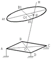
图3为四点支撑示意图。Figure 3 is a schematic diagram of four-point support.
图4为偏转第一步示意图。Figure 4 is a schematic diagram of the first step of deflection.
图5为偏转第二步示意图。FIG. 5 is a schematic diagram of the second step of deflection.
图6为电动机机驱动机构示意图。FIG. 6 is a schematic diagram of a motor drive mechanism.
图7为头部偏转控制系统框图。FIG. 7 is a block diagram of the head deflection control system.
具体实施方式Detailed ways
下面结合附图及具体实施例对本发明做进一步的介绍。The present invention will be further introduced below with reference to the accompanying drawings and specific embodiments.
本发明的一种可产生大角度偏转的飞行体偏转头控制方法,基于四点支撑方法,采用四个支撑杆和一个万向节把飞行体的头部与主体相连,通过四个支撑杆的不同伸缩,使得飞行体的头部围绕万向节偏转,四个支撑杆不同的伸缩长度,可以使飞行体头部偏转到需要的方向,从而实现飞行体飞行轨迹的改变。根据四点支撑法原理,采用电机作为驱动元件设计出支撑杆的伸缩驱动机构。A method for controlling the deflection head of a flying body capable of producing large-angle deflection of the present invention is based on a four-point support method, using four support rods and a universal joint to connect the head of the flying body with the main body, and through the four support rods The different telescopic lengths of the four support rods make the head of the flying body deflect around the universal joint, and the different telescopic lengths of the four support rods can deflect the head of the flying body to the required direction, thereby realizing the change of the flight trajectory of the flying body. According to the principle of the four-point support method, the telescopic drive mechanism of the support rod is designed by using the motor as the driving element.
为了便于理解,如图1所示,以飞行体的弹体质点为坐标原点建立弹体坐标系,飞行器主体轴线为x轴,相垂直的径向分别为y轴和z轴,定义飞行体头部轴线与xoz平面的夹角δy为俯仰角,头部轴线在xoz平面的投影与x轴的夹角δz为偏角。则飞行体头部在空间的偏转角度可以由俯仰角δy和偏角δz表示。In order to facilitate understanding, as shown in Figure 1, the projectile coordinate system is established with the projectile mass point of the flying body as the coordinate origin, the main axis of the aircraft is the x-axis, the perpendicular radial directions are the y-axis and the z-axis, respectively, defining the flying body head The angle δ y between the head axis and the xoz plane is the pitch angle, and the angle δ z between the projection of the head axis on the xoz plane and the x axis is the declination angle. Then the deflection angle of the flying body head in space can be represented by the pitch angle δ y and the declination angle δ z .
利用四点支撑的对角两个支撑杆,一个伸长(缩短)、另一个的缩短(伸长)完成头部相对机身的俯仰角δy或偏航角δz(下面论述简称δy与δz)。一对支撑杆和头部偏转角度的关系如图2所示。Using two diagonal support rods supported by four points, one is extended (shortened) and the other is shortened (extended) to complete the pitch angle δ y or yaw angle δ z of the head relative to the fuselage (hereinafter referred to as δ y ) with δ z ). The relationship between a pair of support rods and the deflection angle of the head is shown in Figure 2.
由图2可知,当一个支撑杆伸长△l,同时与其对称的一个支撑杆缩短△l,则连接两杆的水平杆围绕中间的支点旋转a角,其法线(图中带箭头的线)旋转b角,最终到达图中虚线的位置,角度和伸长的关系如下:It can be seen from Figure 2 that when a support rod is elongated by Δl and a support rod symmetrical to it is shortened by Δl, the horizontal rod connecting the two rods rotates around the middle fulcrum by an angle a, and its normal (the line with the arrow in the figure) ) Rotate the angle b, and finally reach the position of the dotted line in the figure. The relationship between the angle and the elongation is as follows:

通过对角的两个支撑杆的伸长和缩短,则连接两个支撑杆的中间杆围绕着中间的支点旋转,其法线也围绕着支点旋转,如果以飞行体的头部安装在法线的位置,其对称轴与法线重合,则当两个支撑杆动作时,飞行体的头部围绕支点旋转,从而实现一个偏转角,两对支撑杆的联合,完成飞行体头部的在空间的偏转(δy和δz)。Through the extension and shortening of the two diagonal support rods, the middle rod connecting the two support rods rotates around the middle fulcrum, and its normal also rotates around the fulcrum, if the head of the flying body is installed on the normal , the axis of symmetry coincides with the normal, then when the two support rods move, the head of the flying body rotates around the fulcrum, so as to realize a deflection angle, and the combination of the two pairs of support rods completes the space of the head of the flying body. deflection (δ y and δ z ).
为了详细的说明飞行体头部偏转一个角度的过程,把其偏转分为两个步骤,首先由一对对角支撑杆的伸长与缩短完成δy,然后由另外一对支撑杆完成δz。在实际的执行过程中,这两步是同时进行,最终体现为四个支撑杆的不同伸缩长度。In order to explain the process of deflecting the head of the flying body by an angle in detail, the deflection is divided into two steps. First, δ y is completed by the extension and shortening of a pair of diagonal support rods, and then δ z is completed by another pair of support rods. . In the actual execution process, these two steps are carried out at the same time, which is finally reflected in the different telescopic lengths of the four support rods.
如图3所示,以ABCD面代表飞行体头部所在的支撑面(A、B、C、D四个点可理解为四个支撑杆分别与主体铰接点的位置),A1B1C1D1表示偏转头部时,头部轴线所扫过锥体的的一个截面,头部的任何一个偏转角度,其轴线都和A1B1C1D1有唯一对应交点,OO1M为飞行体头部轴线,O为万向节中心(位于ABCD面中心),O1为A1B1C1D1中心。p为飞行体头部处于某个偏转角时,头部轴线与A1B1C1D1的交点。As shown in Figure 3, the ABCD surface represents the support surface where the aircraft head is located (the four points A, B, C, and D can be understood as the positions of the four support rods and the main body hinge points respectively), and A1B1C1D1 represents the deflection head When the axis of the head sweeps a section of the cone, any deflection angle of the head, its axis has a unique corresponding intersection point with A1B1C1D1, OO1M is the axis of the head of the flying body, O is the center of the universal joint (located at ABCD face center), O1 is the center of A1B1C1D1. p is the intersection of the head axis and A1B1C1D1 when the head of the flying body is at a certain deflection angle.
为了使得头部完成p点所示的偏转角度(δy和δz),分如下两步进行:In order to make the head complete the deflection angle (δ y and δ z ) shown at point p, the following two steps are performed:
(1)如图4所示,A点支撑杆伸长Δl=Rtanδy,C支撑杆缩短Δl=Rtanδy,保持B、C长度不变,则OO1M围绕BOD旋转到达p1点,完成飞行体头部相对机身的俯仰角度δy。R为万向节与支撑杆的中心距。(1) As shown in Figure 4, the support rod at point A is elongated by Δl=Rtanδ y , and the support rod at point C is shortened by Δl=Rtanδ y , keeping the lengths of B and C unchanged, then OO 1 M rotates around BOD to reach point p 1 , complete The pitch angle δ y of the head of the flying body relative to the fuselage. R is the center distance between the universal joint and the support rod.
(2)如图5所示,B支撑杆伸长Δk=Rtanδz,D支撑杆缩短Δk=Rtanδz,保持C、D支撑杆的长度不变,则OO1M围绕AOC旋转到达p点,完成飞行体头部相对机身的俯仰角度δz。(2) As shown in Figure 5, the B support rod is elongated by Δk=Rtanδ z , and the D support rod is shortened by Δk=Rtanδ z . Keeping the lengths of the C and D support rods unchanged, then OO 1 M rotates around AOC to reach point p, Complete the pitch angle δ z of the head of the flying body relative to the fuselage.
A1B1和C1D1把A1B1C1D1分成四个区域,飞行体头部在四个区域的偏转,其支撑杆的伸缩关系各不相同。A 1 B 1 and C 1 D 1 divide A 1 B 1 C 1 D 1 into four areas. The deflection of the flying body head in the four areas has different telescopic relations of its support rods.
在A1O1B1区域,需要C杆伸长,A杆缩短,长度为Δl=Rtanδy;D杆伸长,B杆缩短长度为Δk=Rtanδz。同理,在A1O1D1区域,需要C、B杆伸长,A、D杆缩短;在C1O1B1区域,需要A、D杆伸长,C、B杆缩短;在C1O1D11区域,需要A、D杆伸长,C、B杆缩短。In the A 1 O 1 B 1 region, the C rod needs to be extended, the A rod is shortened, and the length is Δl=Rtanδ y ; the D rod is extended, and the B rod is shortened by Δk=Rtanδ z . Similarly, in the A 1 O 1 D 1 area, rods C and B need to be extended, and rods A and D need to be shortened; in the C 1 O 1 B1 area, rods A and D need to be extended, and rods C and B need to be shortened; In the C 1 O 1 D 11 area, rods A and D need to be extended, and rods C and B need to be shortened.
两对对角支撑杆的不同伸缩长度,支持飞行体的头部围绕着万向节点偏转,所以四个支撑杆是驱动头部偏转执行机构的重要执行元件,实现四个支撑杆的伸长和缩短的驱动方式是十分关键的,需要其提供足够的效率和快的响应时间。The different telescopic lengths of the two pairs of diagonal support rods support the deflection of the head of the flying body around the universal joint, so the four support rods are important actuators for driving the head deflection actuator to achieve the elongation and The shortened drive mode is very critical and needs to provide sufficient efficiency and fast response time.
利用电动机机作为支撑杆的驱动元件在技术上没有难点,在工艺上也易于实现,特别是现有采用电动机作为驱动元件在各类飞行体上的运用已经比较成熟。There is no technical difficulty in using the electric motor as the driving element of the support rod, and it is also easy to realize in the process, especially the use of the electric motor as the driving element in various types of flying bodies is relatively mature.
利用电动机作为驱动元件的飞行体头部偏转机构如图6所示,采用电动机驱动的飞行体头部偏转原理:通过安装在飞行体头部的传感器感知飞行体头部的当前位置,并传入计算机,与计算机内产生的要求的飞行体头部位置比较,产生偏差信号,计算机根据偏差信号产生电压,驱动电动机4转动,电动机4带动齿轮3,齿轮3带动齿条2伸长或缩短,从而使与齿条2连接的支撑杆1的伸长或者缩短,直到头部位置偏差信号消除,实现对头部的偏转。The flying body head deflection mechanism using the motor as the driving element is shown in Figure 6. The principle of the flying body head deflection driven by the motor is: the current position of the flying body head is sensed by the sensor installed on the flying body head, and the The computer compares the position of the head of the flying body with the required position in the computer, and generates a deviation signal. The computer generates a voltage according to the deviation signal, drives the motor 4 to rotate, the motor 4 drives the
支撑杆的伸长或者缩短量△k和驱动系统输出轴偏转角度θ、齿轮中径r有关,且△k=θr。The elongation or shortening of the support rod Δk is related to the deflection angle θ of the output shaft of the drive system and the pitch diameter r of the gear, and Δk=θr.
飞行体头部偏转控制系统通过驱动器驱动支撑杆,使四根支撑杆伸长或者缩短,支撑杆驱动飞行体的头部进行偏转,到达命令位置。如图7所示。The flight body head deflection control system drives the support rods through the driver, so that the four support rods are extended or shortened, and the support rods drive the head of the flight body to deflect to reach the command position. As shown in Figure 7.
采用电动机作为驱动元件,则电动机的偏转首先转换为齿轮的转动,齿轮的转动再转换为齿条的伸缩(即支撑杆的伸缩),电动机的传递函数为G(s),齿轮的中径为r,则支撑杆和电动机的合成传递函数为:If the motor is used as the driving element, the deflection of the motor is first converted into the rotation of the gear, and the rotation of the gear is converted into the expansion and contraction of the rack (that is, the expansion and contraction of the support rod). The transfer function of the motor is G(s), and the pitch diameter of the gear is r, the composite transfer function of the support rod and the motor is:

其中
Claims (6)


Priority Applications (1)
| Application Number | Priority Date | Filing Date | Title |
|---|---|---|---|
| CN202210325541.6A CN114740887A (en) | 2022-03-30 | 2022-03-30 | Flight body deflection head control method and system capable of generating large-angle deflection |
Applications Claiming Priority (1)
| Application Number | Priority Date | Filing Date | Title |
|---|---|---|---|
| CN202210325541.6A CN114740887A (en) | 2022-03-30 | 2022-03-30 | Flight body deflection head control method and system capable of generating large-angle deflection |
Publications (1)
| Publication Number | Publication Date |
|---|---|
| CN114740887A true CN114740887A (en) | 2022-07-12 |
Family
ID=82278532
Family Applications (1)
| Application Number | Title | Priority Date | Filing Date |
|---|---|---|---|
| CN202210325541.6A Pending CN114740887A (en) | 2022-03-30 | 2022-03-30 | Flight body deflection head control method and system capable of generating large-angle deflection |
Country Status (1)
| Country | Link |
|---|---|
| CN (1) | CN114740887A (en) |
Cited By (1)
| Publication number | Priority date | Publication date | Assignee | Title |
|---|---|---|---|---|
| CN114987742A (en) * | 2022-08-08 | 2022-09-02 | 陕西科技大学 | Aircraft head deflection control method and structure |
Citations (9)
| Publication number | Priority date | Publication date | Assignee | Title |
|---|---|---|---|---|
| FR955594A (en) * | 1950-01-17 | |||
| DE3031772A1 (en) * | 1980-08-22 | 1982-04-29 | Nikolaj Georgievič Bobovnikov | Pressure cylinder for grinding machine - is articulated to four-link unit, with grinding head drive via telescopic cardan shaft |
| CN104192311A (en) * | 2014-08-28 | 2014-12-10 | 西北工业大学 | Drive device for head deflection of bevel gear push-rod type aircraft |
| CN207217741U (en) * | 2017-10-13 | 2018-04-10 | 南京瑞安腾企业管理咨询有限公司 | A kind of high flux satellite network signal ship-board antenna |
| CN110154009A (en) * | 2019-06-14 | 2019-08-23 | 李忠吉 | A kind of bionic snake-shaped robot |
| CN111678386A (en) * | 2020-07-03 | 2020-09-18 | 南京航空航天大学 | An aircraft head deflection control device |
| CN212783771U (en) * | 2020-10-19 | 2021-03-23 | 盐城市星地通信设备有限公司 | Satellite antenna angle deflection mechanism |
| CN113772087A (en) * | 2021-10-15 | 2021-12-10 | 南京理工大学 | Variant aircraft with variable sweepback wings and head deflection |
| CN114237295A (en) * | 2021-12-20 | 2022-03-25 | 北京航空航天大学 | Unconventional flight control technology for high-agility air-to-air missile at large angle of attack |
-
2022
- 2022-03-30 CN CN202210325541.6A patent/CN114740887A/en active Pending
Patent Citations (9)
| Publication number | Priority date | Publication date | Assignee | Title |
|---|---|---|---|---|
| FR955594A (en) * | 1950-01-17 | |||
| DE3031772A1 (en) * | 1980-08-22 | 1982-04-29 | Nikolaj Georgievič Bobovnikov | Pressure cylinder for grinding machine - is articulated to four-link unit, with grinding head drive via telescopic cardan shaft |
| CN104192311A (en) * | 2014-08-28 | 2014-12-10 | 西北工业大学 | Drive device for head deflection of bevel gear push-rod type aircraft |
| CN207217741U (en) * | 2017-10-13 | 2018-04-10 | 南京瑞安腾企业管理咨询有限公司 | A kind of high flux satellite network signal ship-board antenna |
| CN110154009A (en) * | 2019-06-14 | 2019-08-23 | 李忠吉 | A kind of bionic snake-shaped robot |
| CN111678386A (en) * | 2020-07-03 | 2020-09-18 | 南京航空航天大学 | An aircraft head deflection control device |
| CN212783771U (en) * | 2020-10-19 | 2021-03-23 | 盐城市星地通信设备有限公司 | Satellite antenna angle deflection mechanism |
| CN113772087A (en) * | 2021-10-15 | 2021-12-10 | 南京理工大学 | Variant aircraft with variable sweepback wings and head deflection |
| CN114237295A (en) * | 2021-12-20 | 2022-03-25 | 北京航空航天大学 | Unconventional flight control technology for high-agility air-to-air missile at large angle of attack |
Cited By (2)
| Publication number | Priority date | Publication date | Assignee | Title |
|---|---|---|---|---|
| CN114987742A (en) * | 2022-08-08 | 2022-09-02 | 陕西科技大学 | Aircraft head deflection control method and structure |
| CN114987742B (en) * | 2022-08-08 | 2022-11-04 | 陕西科技大学 | Aircraft head deflection control method and structure |
Similar Documents
| Publication | Publication Date | Title |
|---|---|---|
| US7798443B2 (en) | Composite material for geometric morphing wing | |
| US8074925B2 (en) | Aircraft attitude control configuration | |
| US8418968B2 (en) | Mechanism for changing the shape of a control surface | |
| US12486019B2 (en) | Three-dimensional extension linkage for aircraft | |
| US5366176A (en) | Feedback-stabilized aerodynamically overbalanced lifting/control surface for aircraft | |
| US7195210B2 (en) | Fiber matrix for a geometric morphing wing | |
| US8434712B1 (en) | Methods and apparatus for driving rotational elements of a vehicle | |
| CN110160730A (en) | The device and method of testing flying vehicle Halo vest performance in a kind of high-speed wind tunnel | |
| US20250326499A1 (en) | System and method for adjusting forces on rotating body using aerodynamic means | |
| US11053003B2 (en) | Cyclorotor thrust control, transmission and mounting system | |
| CN104192311B (en) | A kind of finishing bevel gear cuter push-down Vehicle nose deflection driven device | |
| CN114740887A (en) | Flight body deflection head control method and system capable of generating large-angle deflection | |
| WO2024041584A1 (en) | Rotary aircraft launching apparatus and system | |
| JPH09240599A (en) | Rocket control method by adjustment of thrust of engine | |
| US8235329B1 (en) | Dynamically actuated adaptive control structures | |
| CN114987742B (en) | Aircraft head deflection control method and structure | |
| US11345460B1 (en) | Rotatable empennage for an aircraft | |
| CN111412083B (en) | Method for determining length change of servo actuator | |
| CN217456332U (en) | Deformable wing device, wing and flight equipment | |
| CN117566145A (en) | An aircraft suitable for operations in small spaces | |
| CN114572384A (en) | Attitude controllable module unit, aircraft and attitude control method | |
| CN119585175A (en) | Multi-layer swing rotor reaction force anti-strong wind aircraft | |
| CN115477006B (en) | A dual-axis tilt vector rotor aircraft and its disturbance compensation control method | |
| CN117489491A (en) | Thrust vector control device for spray pipe | |
| CN117262279B (en) | I-shaped variant rotor craft and dynamic reconfiguration control method |
Legal Events
| Date | Code | Title | Description |
|---|---|---|---|
| PB01 | Publication | ||
| PB01 | Publication | ||
| SE01 | Entry into force of request for substantive examination | ||
| SE01 | Entry into force of request for substantive examination |