CN114717882B - Full-assembled ballastless track capable of preventing train derailing and overturning - Google Patents
Full-assembled ballastless track capable of preventing train derailing and overturning Download PDFInfo
- Publication number
- CN114717882B CN114717882B CN202210572047.XA CN202210572047A CN114717882B CN 114717882 B CN114717882 B CN 114717882B CN 202210572047 A CN202210572047 A CN 202210572047A CN 114717882 B CN114717882 B CN 114717882B
- Authority
- CN
- China
- Prior art keywords
- track beam
- track
- boss
- base
- fixed
- Prior art date
- Legal status (The legal status is an assumption and is not a legal conclusion. Google has not performed a legal analysis and makes no representation as to the accuracy of the status listed.)
- Active
Links
Images


Classifications
-
- E—FIXED CONSTRUCTIONS
- E01—CONSTRUCTION OF ROADS, RAILWAYS, OR BRIDGES
- E01B—PERMANENT WAY; PERMANENT-WAY TOOLS; MACHINES FOR MAKING RAILWAYS OF ALL KINDS
- E01B1/00—Ballastway; Other means for supporting the sleepers or the track; Drainage of the ballastway
- E01B1/002—Ballastless track, e.g. concrete slab trackway, or with asphalt layers
-
- E—FIXED CONSTRUCTIONS
- E01—CONSTRUCTION OF ROADS, RAILWAYS, OR BRIDGES
- E01B—PERMANENT WAY; PERMANENT-WAY TOOLS; MACHINES FOR MAKING RAILWAYS OF ALL KINDS
- E01B2/00—General structure of permanent way
-
- E—FIXED CONSTRUCTIONS
- E01—CONSTRUCTION OF ROADS, RAILWAYS, OR BRIDGES
- E01B—PERMANENT WAY; PERMANENT-WAY TOOLS; MACHINES FOR MAKING RAILWAYS OF ALL KINDS
- E01B9/00—Fastening rails on sleepers, or the like
- E01B9/68—Pads or the like, e.g. of wood, rubber, placed under the rail, tie-plate, or chair
-
- Y—GENERAL TAGGING OF NEW TECHNOLOGICAL DEVELOPMENTS; GENERAL TAGGING OF CROSS-SECTIONAL TECHNOLOGIES SPANNING OVER SEVERAL SECTIONS OF THE IPC; TECHNICAL SUBJECTS COVERED BY FORMER USPC CROSS-REFERENCE ART COLLECTIONS [XRACs] AND DIGESTS
- Y02—TECHNOLOGIES OR APPLICATIONS FOR MITIGATION OR ADAPTATION AGAINST CLIMATE CHANGE
- Y02A—TECHNOLOGIES FOR ADAPTATION TO CLIMATE CHANGE
- Y02A30/00—Adapting or protecting infrastructure or their operation
- Y02A30/30—Adapting or protecting infrastructure or their operation in transportation, e.g. on roads, waterways or railways
Abstract
The invention discloses a full-assembled ballastless track capable of preventing train derailing and overturning, which comprises a base and two track structures, wherein the base comprises a first boss seat, a second boss seat and a steel bar truss, and the first boss seat and the second boss seat are connected through the steel bar truss; the two track structures are the same and respectively comprise a track beam, a supporting base plate, an energy absorption structure and a limiting block, wherein the end part of the track beam is provided with a limiting hole, and a first lug of the first lug boss base is inserted into the limiting hole of one track beam; a second lug of the second lug boss seat is inserted into a limiting hole of the other track beam; supporting base plates are respectively arranged between the bottom end of the track beam and the first boss base and between the bottom end of the track beam and the second boss base; energy absorption structures are filled between the first lug and the corresponding limiting hole and between the second lug and the corresponding limiting hole. The invention can prevent the train from overturning to rush out of the bridge or invade into an adjacent line after the train is derailed, reduces casualties and does not influence maintenance operations such as rail grinding and the like.
Description
Technical Field
The invention relates to the technical field of ballastless tracks for railway and subway engineering, in particular to a full-assembled ballastless track capable of preventing train derailment and overturning.
Background
At present, the railway operation mileage of China is close to 15 kilometers, wherein the high-speed railway operation mileage is close to 4 kilometers, the ballastless track is comprehensively applied to the high-speed railway, long and large tunnels and tunnel groups with the advantages of high smoothness and high stability, and the business mileage reaches over 2 kilometers.
However, because the railway in China has high running speed, high density and more passengers, and spans different geological areas and complex temperature areas, the problem of poor maintainability of the existing ballastless track is increasingly prominent, particularly the proportion of bridges and tunnels of the high-speed railway in China is high, the existing ballastless track structure does not have the function of preventing the train from overturning after derailing, and a new structure needs to be further developed to ensure the safety of the high-speed railway.
Specifically, the conventional ballastless track structure mainly comprises a prefabricated plate type and a sleeper type, wherein the prefabricated plate type ballastless track realizes the support and the positioning of a track plate by filling cement emulsified asphalt mortar (CA mortar) or self-compacting concrete under the prefabricated track plate on site to form a layered structure form, under the action of temperature gradient, the warping of the track plate causes the non-uniformity of the support under the plate, the problems of crack separation and filling layer damage are prominent, particularly, the II-type CA mortar is used as an adhesive structure layer, and the problem of separation of the track plate and a base plate caused by the performance degradation of the II-type CA mortar directly influences the railway operation safety; the prefabricated sleeper type ballastless track integrates the prefabricated sleepers through cast-in-place concrete to form a reinforced concrete track bed plate structure with continuous bridge units, roadbeds and tunnel sections, and due to the fact that new and old concrete deforms incoordinatively after the concrete is cast in place, shrinkage cracks are easily formed between the prefabricated sleeper and the new cast concrete interface and further expand under the action of dynamic load of a train, the prefabricated sleeper can be separated from the bed plate when serious, and high smoothness and high stability of the track are affected. In addition, the maintenance of the prefabricated slab type and the sleeper type ballastless track can be realized only by adjusting the fasteners, and when a large disease is generated, a filling layer or a track bed plate needs to be chiseled off, and the operation of a travelling crane of one line is often needed to be interrupted; simultaneously, all there is not anti-overturning device behind the train derailment at road bed and tunnel section, only set up crashproof wall in bridge section bridge both sides, can't effectively deal with the safety risk that the train derailed and topples, set up the anticreep guardrail device in rail both sides, not only increased track rigidity and cost, need demolish when the rail is polished moreover, increased the operation work load.
Therefore, it is an urgent need to solve the problems in the art to provide a stable and reliable full-assembled ballastless track capable of preventing train derailment and overturning.
Disclosure of Invention
In view of the above, the invention provides a train derailing prevention overturning full-assembled ballastless track, which can prevent a train from overturning to rush out of a bridge or invade into an adjacent line after the train derails, reduce casualties, and does not influence maintenance operations such as steel rail grinding and the like; meanwhile, the method has the characteristics of simple operation of main component prefabrication and assembly, construction and installation, maintenance and adjustment, large adjustable quantity and the like, reduces the temperature field effect, has the capability of adapting to large deformation of a foundation, and can ensure high smoothness and high stability of a ballastless track structure.
In order to achieve the purpose, the invention adopts the following technical scheme:
the utility model provides a prevent that train derails and topples complete assembled ballastless track, includes:
the steel bar truss type steel bar connecting device comprises a plurality of bases, wherein each base comprises a first boss base, a second boss base and a steel bar truss, and the first boss base and the second boss base are connected into a whole through the steel bar truss at the bottom of the first boss base and the second boss base;
the first track beam and the second track beam are distributed in parallel; the two ends of the first track beam are respectively provided with a first limiting hole, and the first convex blocks of the two first convex pedestal are respectively inserted into the two first limiting holes; the two ends of the second track beam are respectively provided with a second limiting hole, and the second lugs of the two second boss seats are respectively inserted into the two second limiting holes;
the first supporting cushion plate is placed between the bottom end of the first track beam and the platform of the first boss base; the second support base plate is placed between the bottom end of the second track beam and the platform of the second boss base;
the energy absorption structure comprises a first energy absorption structure and a second energy absorption structure, wherein the first energy absorption structure and the second energy absorption structure are both made of elastomer materials; the first energy absorption structure is filled between the first bump and the first limiting hole; the second energy-absorbing structure is filled between the second bump and the second limiting hole;
the first limiting block and the second limiting block are both made of elastomer materials; the first limiting block is fixed at the top of the first bump through a bolt and is positioned in the first limiting hole; the second limiting block is fixed at the top of the second bump through a bolt and is positioned in the second limiting hole;
the steel rail comprises a first steel rail and a second steel rail which are distributed in parallel; the first steel rail is fixed at the top of the first track beam through a fastener; the second steel rail is fixed to the top of the second track beam through a fastener.
The first stop blocks are respectively fixed on two sides of the platform of the first boss base so as to limit the position of the first supporting cushion plate; and the second stoppers are respectively fixed at two sides of the platform of the second boss seat to limit the position of the second supporting cushion plate.
Furthermore, the first supporting base plate and the second supporting base plate have the same structure and respectively comprise a plastic base plate, a steel base plate and an elastic base plate which are sequentially stacked from top to bottom.
The first rail bearing platforms are fixed at the top of the first rail beam and are uniformly distributed along the length direction of the first rail beam; the first steel rail is fixed on the first rail bearing platforms through fasteners; the second rail bearing platforms are all fixed at the top of the second track beam and are uniformly distributed along the length direction of the second track beam; the second steel rail is fixed on the second rail bearing platforms through fasteners.
Therefore, compared with the prior art, the invention provides a full-assembled ballastless track capable of preventing train derailing and overturning, which comprises the following steps:
1) the energy of the wheel impacting the track beam is absorbed by the limiting block and is transmitted to the boss base which is connected with the foundation into a whole through the convex block, the integral derailing impact resistance is strong, the train can be prevented from overturning after derailing, casualties are reduced, the first track beam and the second track beam have certain heights, and after the train is derailed, the wheel on one side is restrained between the first track beam and the second track beam and cannot rush out of the line track;
2) the track main body structure mainly comprises a track beam, a supporting base plate and a limiting block, the number of components is small, the supporting state is simpler and clearer than that of the existing prefabricated plate type and sleeper type ballastless tracks, the force transmission path is clear, the stress state is clear, and the reliability, the usability, the maintainability and the safety of the track structure can be ensured;
3) the construction is simple and convenient, the main components are manufactured in factories, except for prefabricating the first boss seat and laying the second boss seat, concrete needs to be cast in situ, other components are assembled in situ, the industrialization, informatization, greening and rapid manufacturing construction levels of the track structure are improved, and the track engineering quality and the construction period can be ensured;
4) the adjustment of the track beam is realized by adding or extracting part of base plates, so that the maintainability of the ballastless track is improved, the height adjustment function is particularly realized, the defect that the height adjustment amount of a fastener is only 4mm is overcome, and a solution is provided for solving the problem that the ballastless track cannot be adjusted to be low after the upper arch deformation such as roadbed frost heaving, roadbed soil expansion, tunnel bottom bulging and the like in the conventional railway is solved;
5) the track beam is small in size, strong in capability of adapting to complex temperature conditions, simple and convenient to maintain and adjust, large in applicable foundation, good in deformation conditions, simple in emergency repair transition measures after damage, small in construction workload, short in time and good in restorability, and is suitable for areas with high seismic intensity.
Drawings
In order to more clearly illustrate the embodiments of the present invention or the technical solutions in the prior art, the drawings used in the description of the embodiments or the prior art will be briefly described below, it is obvious that the drawings in the following description are only embodiments of the present invention, and for those skilled in the art, other drawings can be obtained according to the provided drawings without creative efforts.
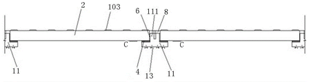
Fig. 1 is a top view of a fully assembled ballastless track for preventing train derailment and overturning provided by the invention;
FIG. 2 is a sectional view taken along line A-A of FIG. 1;
FIG. 3 is a cross-sectional view taken along line B-B of FIG. 1;
FIG. 4 is a cross-sectional view taken along line C-C of FIG. 3;
FIG. 5 is a cross-sectional view taken along line D-D of FIG. 1;
fig. 6 is an enlarged schematic view of part E in fig. 5.
Detailed Description
The technical solutions in the embodiments of the present invention will be clearly and completely described below with reference to the drawings in the embodiments of the present invention, and it is obvious that the described embodiments are only a part of the embodiments of the present invention, and not all of the embodiments. All other embodiments, which can be derived by a person skilled in the art from the embodiments given herein without making any creative effort, shall fall within the protection scope of the present invention.
As shown in fig. 1-6, an embodiment of the present invention discloses a full-assembled ballastless track for preventing train derailment and overturn, including:
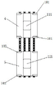
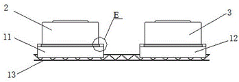
the steel bar truss type steel bar connecting device comprises a plurality of bases 1, wherein each base 1 comprises a first boss base 11, a second boss base 12 and a steel bar truss 13, and the first boss base 11 and the second boss base 12 are connected into a whole through the steel bar truss 13 at the bottom of the first boss base and the second boss base; in the present embodiment, the first boss base 11 and the second boss base 12 are integrated with the foundation by cast-in-place concrete;
the track comprises a first track beam 2 and a second track beam 3, wherein the first track beam 2 and the second track beam 3 are distributed in parallel; the two end parts of the first track beam 2 are respectively provided with a first limiting hole, and the first lugs 111 of the two first boss seats 11 are respectively inserted into the two first limiting holes; the two end parts of the second track beam 3 are respectively provided with a second limiting hole, and the second lugs 121 of the two second boss seats 12 are respectively inserted into the two second limiting holes; in this embodiment, the first track beam 2 and the second track beam 3 are both prefabricated by reinforced concrete, two structures of prestressed concrete and common reinforced concrete are adopted, the structural dimensions are determined according to the type of the railway rolling stock, the running speed of the train, the axle weight and the type of the off-line foundation, wherein the heights of the first track beam 2 and the second track beam 3 need to ensure that the train runs between the first track beam 2 and the second track beam 3 after derailing, in this embodiment, the distance between the first track beam 2 and the second track beam 3 is 600mm, and the heights of the first track beam 2 and the second track beam 3 are both 300 mm.
A first support mat 4 and a second support mat 5, the first support mat 4 being placed between the bottom end of the first track beam 2 and the platform of the first boss base 11; the second bolster plate 5 is placed between the bottom end of the second rail beam 3 and the platform of the second boss base 12;
the energy absorption structure comprises a first energy absorption structure 6 and a second energy absorption structure 7, wherein the first energy absorption structure 6 and the second energy absorption structure 7 are both made of elastomer materials; the first energy absorbing structure 6 is filled between the first bump 111 and the first limiting hole; the second energy-absorbing structure 7 is filled between the second bump 121 and the second limiting hole; the first energy absorption structure 6 can buffer the collision between the first track beam 2 and the first bump 111 under the action of a train, absorb the impact energy transmitted to the first bump 111 by the first track beam 2, and can meet the requirement of adjusting the longitudinal and transverse positions of the first track beam 2 by adjusting the thickness of the energy absorption structure 6, and the second energy absorption structure 7 is similar to the first energy absorption structure;
the first limiting block 8 and the second limiting block 9 are made of elastomer materials; the first limiting block 8 is fixed on the top of the first bump 111 through a bolt and is positioned in the first limiting hole; the second limiting block 9 is fixed on the top of the second bump 121 through a bolt and is positioned in the second limiting hole; the first limiting blocks 8 arranged in the first limiting holes have longitudinal and transverse adjustment amount, and can meet the requirement of longitudinal and transverse position adjustment of the first track beam 2 by matching with the adjustment of the thickness of the first energy absorbing structure 6, and the second limiting blocks 9 are similar;
the first steel rail and the second steel rail are distributed in parallel; the first steel rail is fixed on the top of the first track beam 2 through a fastener; the second steel rail is fixed on the top of the second track beam 3 through a fastener.
The invention comprises the following steps:
1) the energy that the wheel impacted the track roof beam is absorbed by the stopper, passes to on the boss seat even as an organic whole with the basis through the lug, and whole anti derailment impact capacity is strong, can prevent that the train from toppling after derailing, reduces the casualties to first track roof beam 2 and second track roof beam 3 have certain height, and after the train derails, one side wheel is retrained in first track roof beam 2 and second track roof beam 3 in the middle of, can not rush out this line track.
2) The track main body structure mainly comprises a track beam, a supporting base plate and a limiting block, the number of components is small, the supporting state is simpler and clearer than that of the existing prefabricated plate type and sleeper type ballastless tracks, the force transmission path is clear, the stress state is clear, and the reliability, the usability, the maintainability and the safety of the track structure can be ensured;
3) the construction is simple and convenient, the main components are manufactured in factories, except that the first boss seat 11 and the second boss seat 12 are prefabricated and concrete is required to be poured on site, the other components are assembled on site, the industrialization, informatization, greening and rapid manufacturing construction levels of the track structure are improved, and the track engineering quality and the construction period can be ensured;
4) the adjustment of the track beam is realized by adding or extracting part of base plates, so that the maintainability of the ballastless track is improved, the height adjustment function is particularly realized, the defect that the height adjustment amount of a fastener is only 4mm is overcome, and a solution is provided for solving the problem that the ballastless track cannot be adjusted to be low after the upper arch deformation such as roadbed frost heaving, roadbed soil expansion, tunnel bottom bulging and the like in the conventional railway is solved;
5) the track beam is small in size, strong in capability of adapting to complex temperature conditions, simple and convenient to maintain and adjust, large in applicable foundation, good in deformation conditions, simple in emergency repair transition measures after damage, small in construction workload, short in time and good in restorability when the first boss seat 11, the second boss seat 12 and the track beam are replaced, and the track beam is suitable for areas with high seismic intensity.
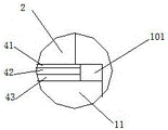
Specifically, the device further comprises a plurality of first stoppers 101 and a plurality of second stoppers 102, wherein the plurality of first stoppers 101 are respectively fixed on two sides of the platform of the first boss base 11 to limit the position of the first support shim plate 4; a plurality of second stoppers 102 are respectively fixed to both sides of the stage of the second boss base 12 to restrict the position of the second bolster plate 5. In this embodiment, the first stopper 101 is fixed to the first boss base 11 by a pre-buried sleeve, so as to prevent the first supporting pad 4 from moving, and the second stopper 102 is the same.
Specifically, the first support mat 4 and the second support mat 5 have the same structure, and each of them includes a plastic mat 41, a steel mat 42 and an elastic mat 43, which are stacked in sequence from top to bottom. Wherein the plastic backing plate 41 is used for adjusting the elevation of the first track beam 2 or the second track beam 3, and the elastic backing plate 43 selects reasonable rigidity according to the requirements of vibration and noise reduction.
Specifically, the track structure further comprises a plurality of first track supporting platforms 103 and a plurality of second track supporting platforms 104, wherein the plurality of first track supporting platforms 103 are all fixed on the top of the first track beam 2 and are uniformly distributed along the length direction of the first track beam 2; the first steel rail is fixed on a plurality of first rail bearing platforms 103 through fasteners; the plurality of second rail bearing platforms 104 are all fixed on the top of the second track beam 3 and are uniformly distributed along the length direction of the second track beam 3; the second rail is secured to a plurality of second rail support platforms 104 by fasteners.
The paving method comprises the following steps: according to the line shape and the track design elevation, a CP III fine measurement net is adopted to firstly position and lay a base, then the first track beam 2 and the second track beam 3 are coarsely paved, namely, a first limit hole of the first track beam 2 is placed on a first lug 111 in an aligning way, the height of a first supporting cushion plate 4 at the bottom of the first track beam 2 is coarsely adjusted, so that the first track beam 2 is in a supporting state, a second limit hole of the second track beam 3 is placed on a second lug 121 in an aligning way, the height of a second supporting cushion plate 5 at the bottom of the second track beam 3 is coarsely adjusted, so that the second track beam 3 is in a supporting state, the first track beam 2 and the second track beam 3 are finely adjusted to achieve the static laying precision by utilizing the fine measurement net and a plastic gasket 41, a first stop block 101 and a second stop block 102 are installed, a first energy absorption structure 6 is installed between the first limit hole and the first lug 111, a second energy absorption structure 7 is installed between the second limit hole and the second lug 121, the first limiting blocks 8 are fastened on the first convex blocks 111 through bolts, the second limiting blocks 9 are fastened on the second convex blocks 121 through bolts, laying of a track beam part is completed, and later-stage steel rail laying and track fine adjustment are the same as those of an existing ballastless track structure.
The maintenance adjusting method comprises the following steps: when the track irregularity exceeds the maintenance and repair standard and cannot be adjusted by the fastener, the maintenance and adjustment can be performed by adjusting the supporting base plate (the first supporting base plate 4 or the second supporting base plate 5) at the bottom of the track beam (the first track beam 2 or the second track beam 3), when the maintenance and adjustment is performed, the fastener in a certain range at both sides of the end of the track beam (the first track beam 2 or the second track beam 3) is firstly loosened, then the fastening bolt and the stopper (the first stopper 101 or the second stopper 102) of the stopper (the first stopper 8 or the second stopper 9) are loosened, the plastic base plate 41 is extracted or increased to increase or decrease the elevation of the track beam (the first track beam 2 or the second track beam 3) through the precision measurement, when the adjustment amount is large, the steel base plate 42 in the supporting base plate (the first supporting base plate 4 or the second supporting base plate 5) can be replaced, and then the stopper (the first stopper 101 or the second stopper 5) for limiting the position of the supporting base plate (the first supporting base plate 4 or the second supporting base plate 5) is installed The steel rail maintenance adjusting device comprises a block 102), an energy absorbing structure (a first energy absorbing structure 6 or a second energy absorbing structure 7) and a limiting block (a first limiting block 8 or a second limiting block 9) are selected according to the size of an adjusting amount, the energy absorbing structure (the first energy absorbing structure 6 or the second energy absorbing structure 7) is installed around a convex block (a first convex block 111 or a second convex block 121) and the limiting block (the first limiting block 8 or the second limiting block 9) is fastened, finally, steel rail fine adjustment is carried out, a fastener is installed, and maintenance adjusting operation of a ballastless track is completed.
The embodiments in the present description are described in a progressive manner, each embodiment focuses on differences from other embodiments, and the same and similar parts among the embodiments are referred to each other. The device disclosed by the embodiment corresponds to the method disclosed by the embodiment, so that the description is simple, and the relevant points can be referred to the method part for description.
The previous description of the disclosed embodiments is provided to enable any person skilled in the art to make or use the present invention. Various modifications to these embodiments will be readily apparent to those skilled in the art, and the generic principles defined herein may be applied to other embodiments without departing from the spirit or scope of the invention. Thus, the present invention is not intended to be limited to the embodiments shown herein but is to be accorded the widest scope consistent with the principles and novel features disclosed herein.
Claims (4)
1. The utility model provides a prevent that train derails and topples complete assembled ballastless track which characterized in that includes:
the steel bar truss type steel bar connecting device comprises a plurality of bases, wherein each base comprises a first boss base, a second boss base and a steel bar truss, and the first boss base and the second boss base are connected into a whole through the steel bar truss at the bottom of the first boss base and the second boss base;
the first track beam and the second track beam are distributed in parallel; the two ends of the first track beam are respectively provided with a first limiting hole, and the first convex blocks of the two first convex pedestal are respectively inserted into the two first limiting holes; the two ends of the second track beam are respectively provided with a second limiting hole, and the second lugs of the two second boss seats are respectively inserted into the two second limiting holes;
the first supporting cushion plate is placed between the bottom end of the first track beam and the platform of the first boss base; the second support base plate is placed between the bottom end of the second track beam and the platform of the second boss base;
the energy absorption structure comprises a first energy absorption structure and a second energy absorption structure, wherein the first energy absorption structure and the second energy absorption structure are both made of elastomer materials; the first energy absorption structure is filled between the first bump and the first limiting hole; the second energy absorption structure is filled between the second lug and the second limiting hole;
the first limiting block and the second limiting block are both made of elastomer materials; the first limiting block is fixed at the top of the first bump through a bolt and is positioned in the first limiting hole; the second limiting block is fixed at the top of the second bump through a bolt and is positioned in the second limiting hole;
the steel rail comprises a first steel rail and a second steel rail which are distributed in parallel; the first steel rail is fixed on the top of the first track beam through a fastener; the second steel rail is fixed to the top of the second track beam through a fastener.
2. The train derailment and overturn preventing fully assembled ballastless track of claim 1, further comprising a plurality of first stoppers and a plurality of second stoppers, wherein the plurality of first stoppers are respectively fixed on two sides of the platform of the first boss base to limit the position of the first supporting cushion plate; and the second stoppers are respectively fixed at two sides of the platform of the second boss seat to limit the position of the second supporting cushion plate.
3. The full-assembled ballastless track capable of preventing train derailment and overturning according to claim 2, wherein the first supporting base plate and the second supporting base plate have the same structure and comprise a plastic base plate, a steel base plate and an elastic base plate which are sequentially stacked from top to bottom.
4. The train derailment and overturn preventing fully assembled ballastless track of claim 1, further comprising a plurality of first rail bearing platforms and a plurality of second rail bearing platforms, wherein the plurality of first rail bearing platforms are all fixed on the top of the first track beam and are uniformly distributed along the length direction of the first track beam; the first steel rail is fixed on the first rail bearing platforms through fasteners; the second rail bearing platforms are all fixed at the top of the second track beam and are uniformly distributed along the length direction of the second track beam; the second steel rail is fixed on the second rail bearing platforms through fasteners.
Priority Applications (1)
| Application Number | Priority Date | Filing Date | Title |
|---|---|---|---|
| CN202210572047.XA CN114717882B (en) | 2022-05-25 | 2022-05-25 | Full-assembled ballastless track capable of preventing train derailing and overturning |
Applications Claiming Priority (1)
| Application Number | Priority Date | Filing Date | Title |
|---|---|---|---|
| CN202210572047.XA CN114717882B (en) | 2022-05-25 | 2022-05-25 | Full-assembled ballastless track capable of preventing train derailing and overturning |
Publications (2)
| Publication Number | Publication Date |
|---|---|
| CN114717882A CN114717882A (en) | 2022-07-08 |
| CN114717882B true CN114717882B (en) | 2022-08-23 |
Family
ID=82230512
Family Applications (1)
| Application Number | Title | Priority Date | Filing Date |
|---|---|---|---|
| CN202210572047.XA Active CN114717882B (en) | 2022-05-25 | 2022-05-25 | Full-assembled ballastless track capable of preventing train derailing and overturning |
Country Status (1)
| Country | Link |
|---|---|
| CN (1) | CN114717882B (en) |
Families Citing this family (1)
| Publication number | Priority date | Publication date | Assignee | Title |
|---|---|---|---|---|
| CN117626721B (en) * | 2024-01-24 | 2024-04-12 | 中国铁道科学研究院集团有限公司铁道建筑研究所 | Construction method of ballastless track system for isolating foundation deformation |
Family Cites Families (8)
| Publication number | Priority date | Publication date | Assignee | Title |
|---|---|---|---|---|
| CN203295904U (en) * | 2013-06-08 | 2013-11-20 | 中铁第一勘察设计院集团有限公司 | Vibration reduction type ballastless track of heavy type mass spring |
| AU2018218192A1 (en) * | 2017-02-13 | 2019-08-29 | Mercury Rail Pty Ltd | Railway track support system, components thereof and construction method |
| CN209066193U (en) * | 2018-09-13 | 2019-07-05 | 中铁二院工程集团有限责任公司 | A kind of plate-type ballastless track construction of overturn-preventing |
| CN109235150A (en) * | 2018-09-13 | 2019-01-18 | 中铁二院工程集团有限责任公司 | A kind of the plate-type ballastless track construction and construction method of overturn-preventing |
| CN209162533U (en) * | 2018-11-21 | 2019-07-26 | 沙洲职业工学院 | The railway track structure of rapid construction on a kind of bridge |
| CN112575669B (en) * | 2019-09-30 | 2022-03-18 | 比亚迪股份有限公司 | Rail beam for rail-mounted vehicle, rail beam unit, and rail beam |
| CN212146900U (en) * | 2020-03-18 | 2020-12-15 | 周兆弟 | Track beam mold and track beam |
| CN111663375B (en) * | 2020-06-18 | 2022-01-04 | 成都市新筑路桥机械股份有限公司 | Novel beam type embedded track system and construction and maintenance process thereof |
-
2022
- 2022-05-25 CN CN202210572047.XA patent/CN114717882B/en active Active
Also Published As
| Publication number | Publication date |
|---|---|
| CN114717882A (en) | 2022-07-08 |
Similar Documents
| Publication | Publication Date | Title |
|---|---|---|
| US9045865B2 (en) | Polymer grouting method for uplifting ballastless track of high-speed rail | |
| GB2513983A (en) | Ballastless track system | |
| CN106758590B (en) | Construction temporary beam for replacing railway track under non-stop condition and construction method | |
| US4905896A (en) | Railroad roadway for high speed rail-mounted vehicles | |
| CN108951306B (en) | Ballast track bed and construction method thereof | |
| CN114717882B (en) | Full-assembled ballastless track capable of preventing train derailing and overturning | |
| Sorgenfrei et al. | Railroad bridges | |
| Bastin | Development of German non-ballasted track forms | |
| KR101132952B1 (en) | Composite rail for tramcar and rail track using the rail | |
| CN100360742C (en) | Plated rail without ballast | |
| RU2373317C2 (en) | Prestressed reinforced concrete slab for railway roads | |
| CN204174481U (en) | Soft clay area modern tram abutment rebound structure | |
| RU2352705C1 (en) | Method for installation of permanent way | |
| CN212452106U (en) | Assembly type floating plate track structure adaptive to traveling direction | |
| CN206385393U (en) | Non-fragment orbit | |
| CN202298390U (en) | Ballastless track rush repair device | |
| CN211772757U (en) | Seamless anti-bumping structure for middle-small span simply-supported highway bridge end part | |
| CN204162955U (en) | Soft clay area modern tram subgrade stiffness transition structure | |
| CN112030613A (en) | Assembly type floating plate track structure adaptive to traveling direction | |
| RU209887U1 (en) | SLEEP FOR TRAMS | |
| Esveld | Innovations in railway track | |
| RU2381317C2 (en) | Railway rail length (versions) | |
| CN217810244U (en) | Damping crossing pillow | |
| CN216712573U (en) | Rubber floating plate type polyurethane curing track bed subway track structure | |
| RU2755804C1 (en) | Ballast-free railway track for cargo and passenger high-speed traffic and method for construction thereof |
Legal Events
| Date | Code | Title | Description |
|---|---|---|---|
| PB01 | Publication | ||
| PB01 | Publication | ||
| SE01 | Entry into force of request for substantive examination | ||
| SE01 | Entry into force of request for substantive examination | ||
| GR01 | Patent grant | ||
| GR01 | Patent grant |